
Note:
Formlabs has sunsetted this material, and it is no longer available for purchase. For information about other Formlabs materials, visit Choosing the right material.

Note:
Formlabs has sunsetted this material, and it is no longer available for purchase. For information about other Formlabs materials, visit Choosing the right material.
Ceramic Resin V1 is a unique material in the Formlabs library. Ceramic Resin V1 is a composite resin engineered for the Form 2. Ceramic Resin V1 is intended to be fired in a kiln or furnace, where the polymer matrix burns away and the model transforms into a silica ceramic part. By 3D printing with Ceramic Resin V1, you can create complex ceramic objects that would be impossible to cast. After firing, Ceramic Resin V1 is:
*When heated too fast, parts may not stably withstand thermal shock, and parts may crack in high temperature environments. Slowly heat parts printed with Ceramic Resin V1 to maintain the parts’ heat resistance.
Ceramic Resin V1 has a lower print success rate than standard Formlabs materials, and therefore benefits from a higher level of skill and attention than other Formlabs products. Ceramic Resin V1 has special requirements for part design and print planning. Some models require modification to fire well. Follow these guidelines to successfully print and fire parts. To increase print success over time, iterate and experiment when designing, printing, firing, and glazing parts printed with Ceramic Resin V1.
Ceramic Resin V1 can be printed at 50 and 100 micron layer heights on the Form 2.
Equipment and supplies
Required equipment:
Recommended supplies:
Notice:
Ceramic Resin V1 will degrade the appearance of the cover of the Form 2 if liquid resin touches the cover. Consider printing splash guards to install on the resin tank to protect the cover from Ceramic Resin V1. Apply clear adhesive-backed plastic film to protect the inside of the cover. Clean with soap and water only.
Design guidelines
Read and follow the design guidelines to achieve success when designing parts to print with Ceramic Resin V1.
Printing overview
After reading all guidelines, review this pre-print checklist when starting a print with Ceramic Resin V1. Skipping one or more of these steps will likely cause your print to fail:
Ceramic Resin V1 can be printed at 50 and 100 micron layer heights on the Form 2.
Print only with a standard Resin Tank. Ceramic Resin V1 is not compatible with Resin Tank LT.
Part size
Consider the unique geometric and dimensional requirements to print successfully with Ceramic Resin V1. Follow the Design guidelines for part design specifics.
Ceramic Resin V1 is best suited for printing small and thin parts. Wall thickness for fired parts should be between 2 and 10 mm. Thicker sections are more likely to crack during the burnout stage of firing and more likely to tear off of supports during printing.
Tip:
Part volume should measure less than 100 mL, and walls should be thin to maximize print success.
Part scale
Scale all parts before printing to account for shrinkage during firing. To scale a Ceramic print:
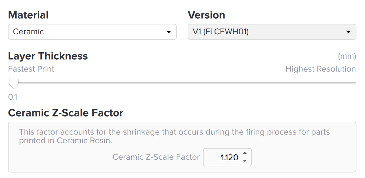
PreForm includes unique setting options for scaling Ceramic Resin V1 parts before printing. Set the Z-Scale Factor after choosing Ceramic Resin V1 in the Print Setup menu. Scale the Z-axis before scaling the global part size.
Ceramic Resin V1 may require experimentation to create dimensionally accurate fired parts. The amount of shrinkage will vary with changes to the firing schedule. Document the Z-Scale Factor and global scale setting used in PreForm. Measure the dimensions of each fired part, then iterate and adjust the scale factors for subsequent prints to refine the final dimensions of fired parts.
Supports
Due to its silica content, Ceramic Resin V1 is heavier than other resins and more fragile in the green (unfired) state. Ceramic Resin V1 requires more support than other Formlabs resins.
Default support settings will typically work for small objects. Larger objects may require larger support touchpoints and higher support density, especially for parts with thick cross-sections. Very small objects may be printable with smaller or fewer support touchpoints.
After printing and removing the supports, smooth the part surface with 120 grit sandpaper to remove support marks. Sanded support touchpoints disappear during the bisque fire
Mixing
Ceramic Resin V1 is silica-filled. The silica filler will separate and settle over time more than other Formlabs materials when stored in the cartridge or tank. Mix the resin in the resin tank and cartridge before each print. Periodically filter debris from the resin to improve print quality.
Vigorously shake the resin cartridge for one minute. If the cartridge has been sitting unused for several days, settled filler may obstruct the bite valve. Ensure the vent cap is closed, then gently push a toothpick through the pre-existing slit in the valve to clear the opening. Insufficient mixing of resin in the cartridge will result in inconsistent ceramic content within the resin, which will cause inconsistent shrinkage between the first and last prints from the cartridge.
Tip:
To prevent clogging the bite valve during prolonged storage, store Ceramic Resin V1 cartridges horizontally, with the label facing down.
Resin tank
Ceramic Resin V1 settles in the tank and must be fully mixed to print successfully. Before each print, remove the tank from the printer and use the wiper or scraper tool to fully mix resin in the tank.
Build platform adherence
Ceramic Resin V1 requires a rough surface on the build platform for proper adherence. The particles in Ceramic Resin V1 erode the rough surface during printing, which can reduce part adherence over time. Firmly scratch the build platform with 180 grit sandpaper before each print to maintain a rough surface on the metal plate. In the case of overadherence, or if parts printed with Ceramic Resin V1 are excessively difficult to remove from the build platform, polish the metal plate with higher grit sandpaper to decrease adhesion.
Notice:
Never print parts with Ceramic Resin V1 directly on the build platform. Always print with a base and supports when printing with Ceramic Resin V1.
Wash and dry
Wash the printed part for 5 minutes in isopropyl alcohol. Use a separate wash bucket to prevent loose ceramic particles from adhering to non-Ceramic parts. Ceramic Resin V1 does not require post-curing, however parts must be fully dry before firing. Allow parts to fully dry before firing.

Firing and glazing instructions
Ceramic Resin V1 is intended to be fired in a kiln or furnace, where the polymer matrix burns away and the model transforms into a silica ceramic part. Follow instructions for firing and glazing Ceramic Resin V1 after printing.

Troubleshooting
For best results, follow the guidelines for designing, printing, firing, and glazing.
Even with a consistent process and settings, each printed part is unique and results are not guaranteed. Capture photos and create process documentation to assist with troubleshooting before requesting support from Formlabs. Document what is consistent and what changes in the processes, steps, and settings used in designing, printing, and firing.
In the case that parts are not coming out as expected, consider the list of troubleshooting causes and solutions.
| PROBLEM | CAUSE | SOLUTION |
|---|---|---|
| Printing | ||
| Print did not start or resin was not properly dispensed | Resin too viscous to flow into tank Cartridge has settled or valve is clogged | Shake the cartridge and clear the valve before printing |
| Part broke off of supports during print | Insufficient support (or) Excessive cross sectional area | Increase support touchpoint size Increase support density |
| Base fell off build platform during print | Build platform too smooth | Re-sand build platform with 180 grit sandpaper |
| Base over-adhered to build platform | Build platform too rough | Polish the build platform with 400 grit sandpaper |
| A print has failed, either completely or partially | Layers or pieces of cured resin stick to the bottom of the tank Particles in the tank | Filter the resin in the resin tank |
| Firing | ||
| Fired or green part has cracks at interior corners | Interior corners too sharp | Part requires larger fillet at corner |
| Unfired part has a prominent line which cracks upon firing | Resin settled during long pause mid-print | Clear cartridge valve and shake well before print Avoid printing interruptions |
| Part slumped or fell apart during firing | Walls too thin (or) Geometry not self-supporting | Increase wall thickness (and / or) Fire on supports |
| Fired part has large cracks in the direction of layers | Walls too thick | Increase burnout hold time at 240 °C |
| Fired part has surface bubbles | Insufficient burnout time | Increase burnout hold time at 240 °C |
| Fired part has large cracks in random directions | Dunting (too fast cooldown) | Slow furnace cooldown rate |
| Fired part has sagged more than expected | Geometry not self supporting | Decrease Sintering Hold time (or) Fire on supports (or) Print custom setter |
| Warp between top and bottom of part | Setter drag | Apply kiln wash to shelf (or) Apply setter sheets to shelf |
| Fired part has skewed to an angle | Ceramic Resin V1 has extra Z-shrinkage when fired | Increase Z-Scale Factor before print |
| Fired part too fragile or porous | Kiln not hot enough | Increase sintering hold time Replace kiln thermocouple |
| Glazing | ||
Glaze soaks into part when fired | Bisque fired part is not fully sintered and is too porous | Increase sintering hold time Replace kiln thermocouple Check peak kiln temperature |
| Part falls apart after glaze firing | Glaze compression of part | Reduce glaze thickness Increase cooldown time Glaze may be incompatible |
Additional resources