
Introducing the Formlabs Texture Engine, currently available in beta. This free, lightweight, web-based app is designed to quickly apply textures to 3D models, ready to be 3D printed. Many plastic parts incorporate surface textures and patterns to enhance the look and feel or to optimize the part for an intended application. Typically, this is done as a secondary process, but 3D printing makes it possible to apply textures and patterns directly to files for printing.
Traditionally, texturing is added directly to the surface of a machined mold via a photochemical etching or laser etching process. 3D printing technologies can produce parts with enough detail to directly print textured parts, but even with the most advanced CAD tools, applying texture can be a difficult process.
To apply a texture to a part, most engineers or product designers export their CAD body as a mesh and bring it into a mesh editing tool designed for artists and designers. With the Formlabs Texture Engine, it’s possible to quickly apply surface textures and patterns to 3D models for fast iterations and the production of textured or patterned 3D printed parts.
Book a Free Consultation
Get in touch with our 3D printing experts for a 1:1 consultation to find the right solution for your business, receive ROI analyses, test prints, and more.
How to Use the Formlabs Texture Engine To Texture 3D Models
1. Export a Mesh To Be Textured
1.1 Start by creating the base geometry in CAD software. Select the faces to texture and create a new surface body from these faces. In Fusion 360, this can be done with the offset tool within the surface toolbox by setting the offset distance to zero.
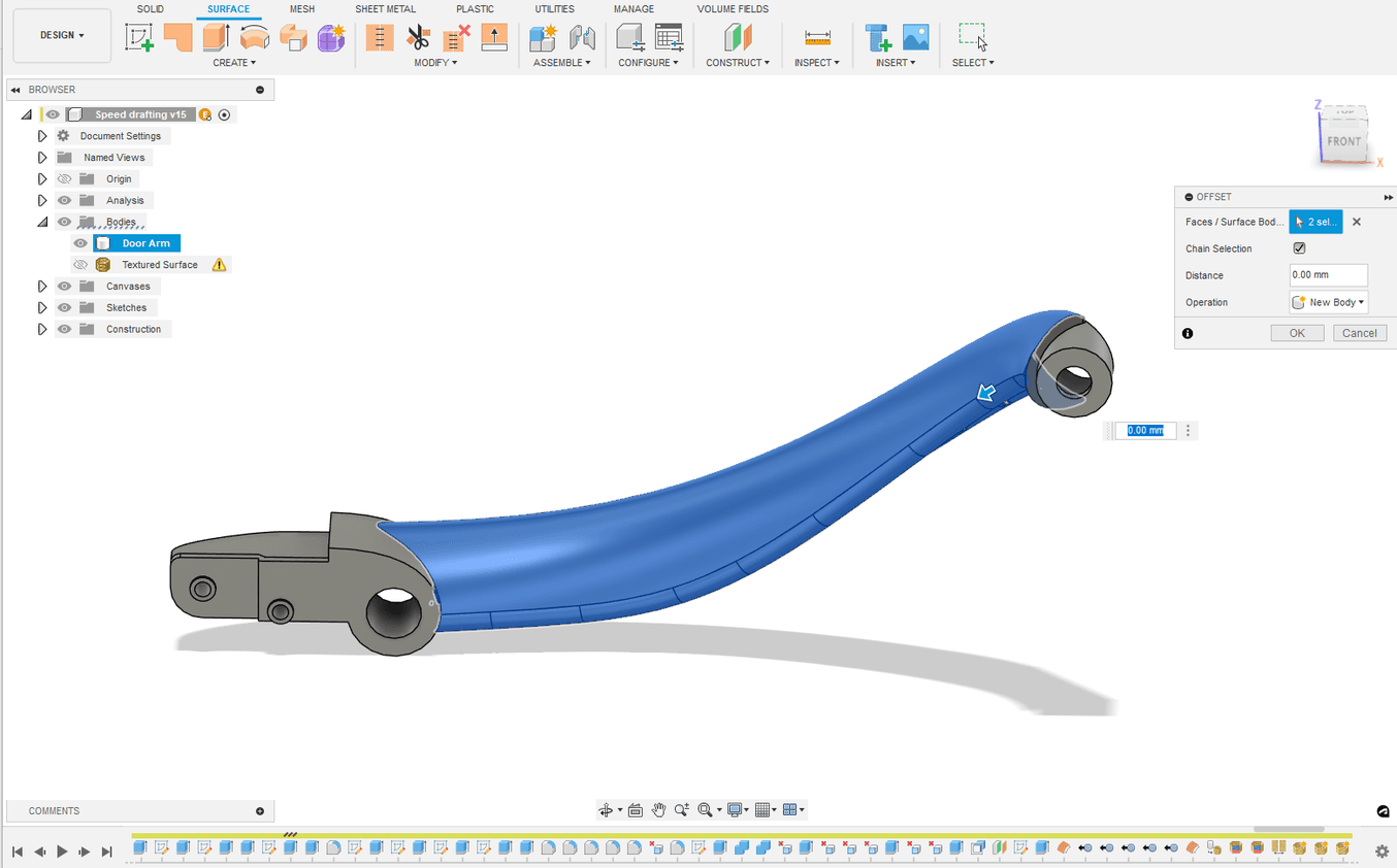
Creating a surface body using (BREP) geometry.
1.2 If working with a mesh instead of a CAD body, this same step can be done by generating surface groups and then splitting the desired surface groups from the main body. This can be done directly in Fusion 360 or can be done in a dedicated mesh editing tool.
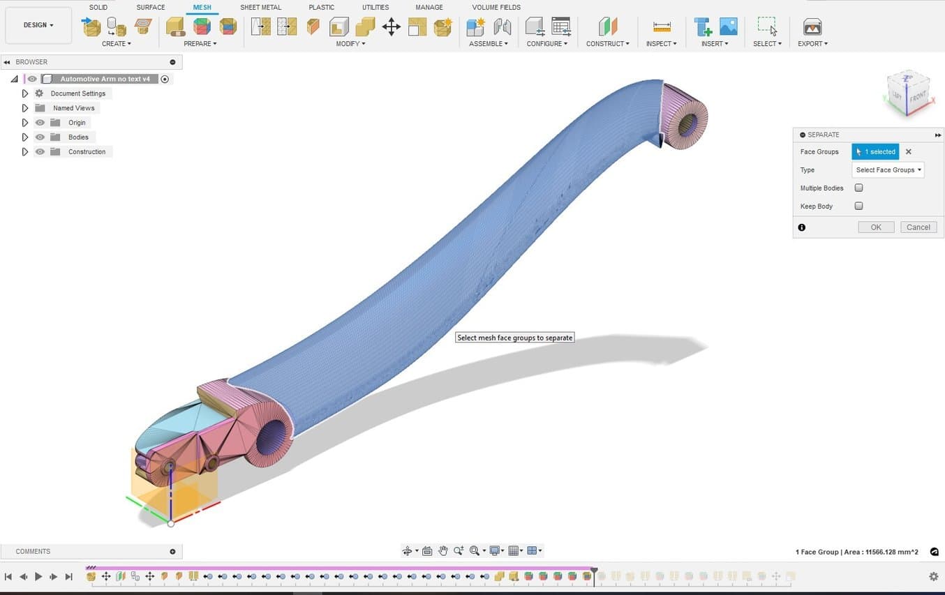
Using mesh face groups to isolate and separate the same geometry.
1.3 When creating the final mesh to be exported, ensure that the mesh density is high and that the spacing between nodes is relatively consistent. Be sure to turn off any “adaptive” meshing options as these will cause inconsistent spacing of the mesh.
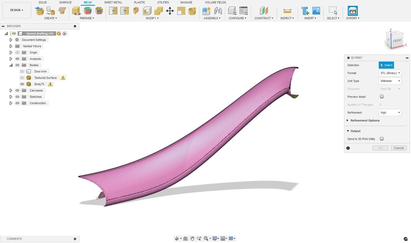
Final Geometry to be exported; note the high mesh density.
2. Bring the Mesh Into the Formlabs Texturing Engine
2.1 Navigate to the Formlabs Texturing Engine. Login to your Dashboard account or register for a free account to ensure you can download the resulting file.
2.2 Import your .stl file.
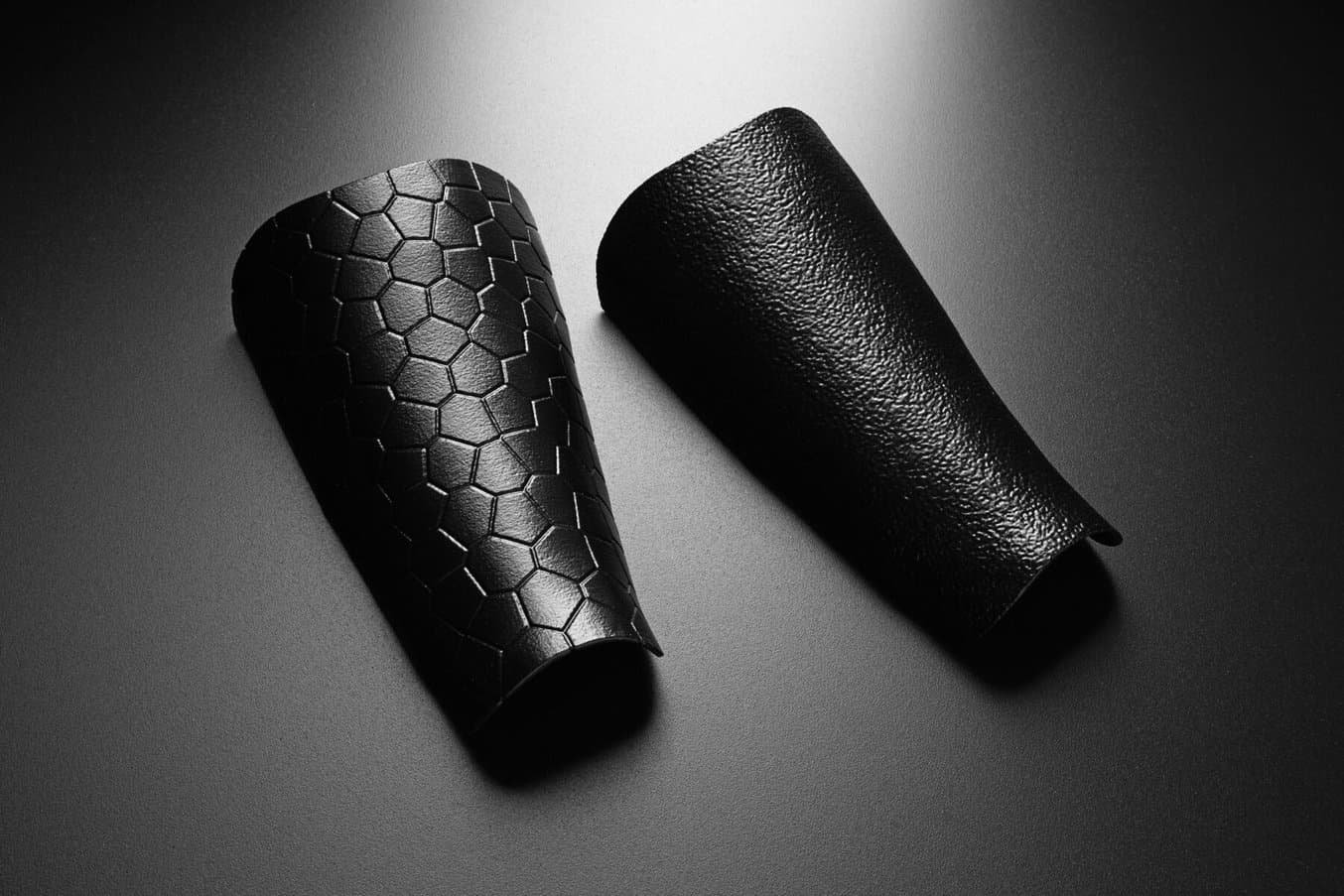
2.3 Apply a displacement map to the model. This is selected from one of the greyscale images by default, but these can also be uploaded in an image file. In this example, we are using a leather displacement map from Ambient CG, which has a broad selection of texturing assets that can be used for free.
2.4 Adjust the parameters of the displacement map by moving the sliders in the toolbar at the left-hand side of the Texture Engine.
i. Scale adjusts the size of the model relative to the displacement model, or the texture’s frequency. A smaller scale will generate larger, coarser textures, and a larger scale for finer, more repetitive texture.
ii. Amplitude is weighting applied to the greyscale texture map. For more pronounced textures, increase this value.
iii. Sharpness controls how the texture maps around curves. This is a nuanced slider and values from 15-30 are recommended for most applications.
iv. Offset controls whether the displacement is embossed or debossed from the surface. When set to one, the texture will be fully embossed. If set to zero, it will be fully debossed. The offset is 0.5 in this example, so the texture will be both above and below the original surface.
v. Max Triangles controls the output detail by setting a triangle limit for the export. The best result will be achieved with this slider set to the maximum value.
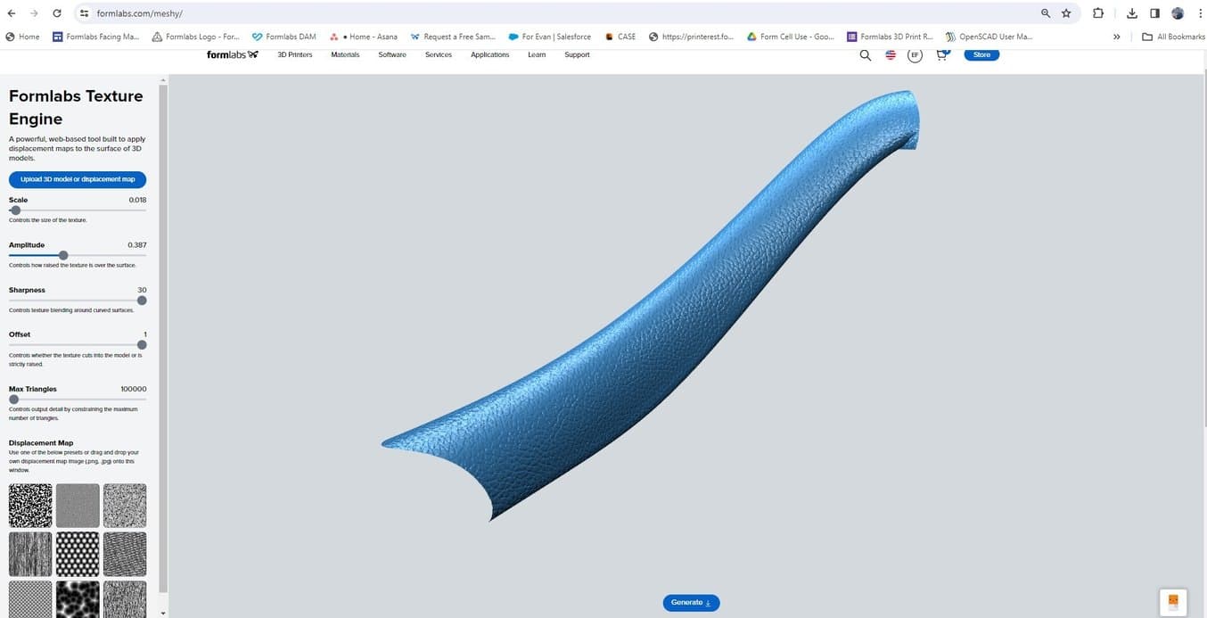
Applying the displacement map in the Formlabs Texture Engine (beta version).
3. Combining the Textured Surface and Exporting
3.1 Hit “generate” to output the final textured part. This new file will have the same coordinates as the original CAD/Mesh file. Ensure you are logged into your Dashboard account or create an account to download your file. Simply import this file into the original CAD tool to see how the texture looks.
3.2 To directly print the part, right-click the top-level component and select “Save as mesh.” This will convert the remaining CAD geometry into a mesh along with the textured mesh surface. This operation will create a non-manifold mesh as the textured surface has not been stitched to the original part. Most slicers, like PreForm, can easily address and fix these errors, but they can also be directly addressed in Fusion or with mesh repair tools if desired.
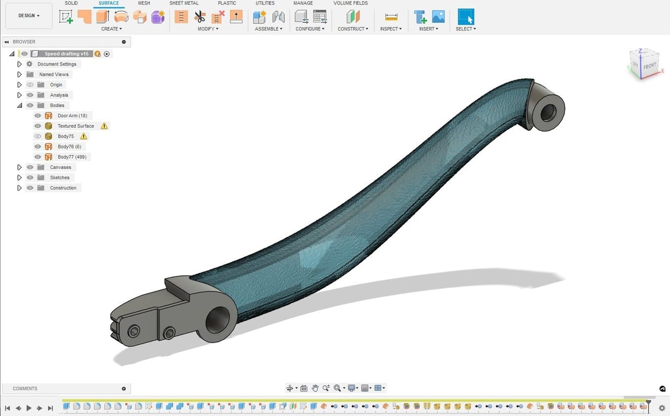
Textured mesh imported back into CAD.
4. Orient and Prepare Part for Printing
4.1 Bring the part into PreForm print preparation software.
4.2 Orient the part to minimize supports that directly touch the texture.
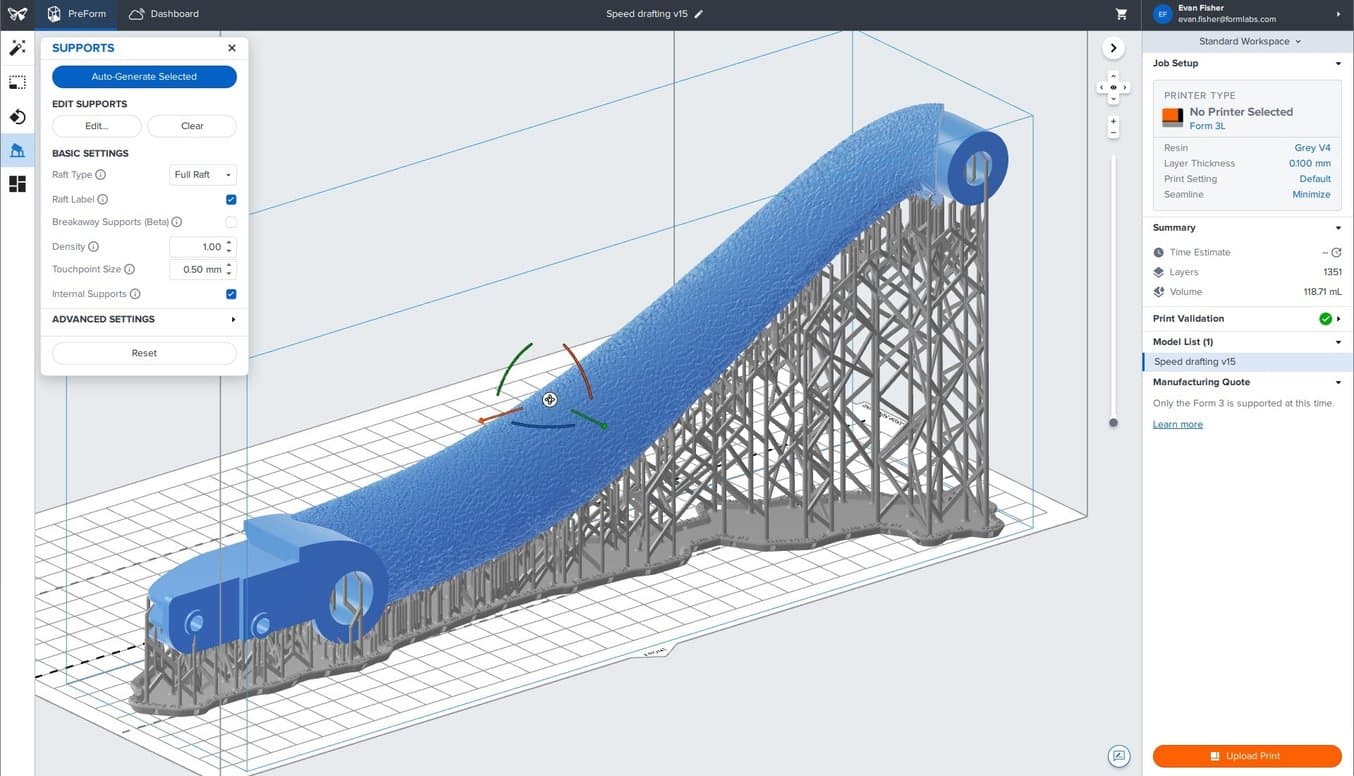
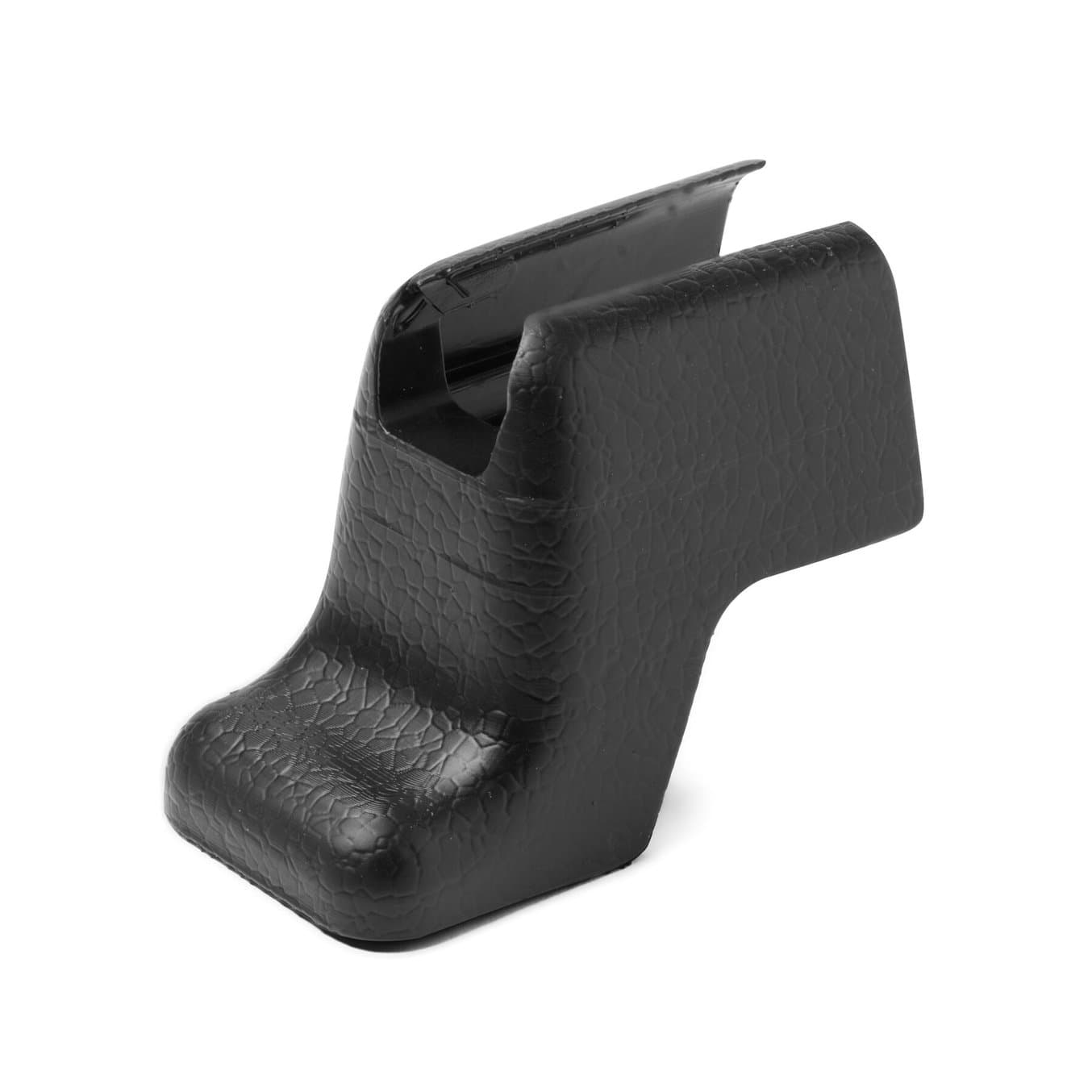
Orienting the textured part in PreForm and adding supports (for SLA printing).
4.3 Avoid placing the textured surface at a shallow angle (<5 degrees) to the build platform to avoid any stair-stepping artifacts on the textured surface.
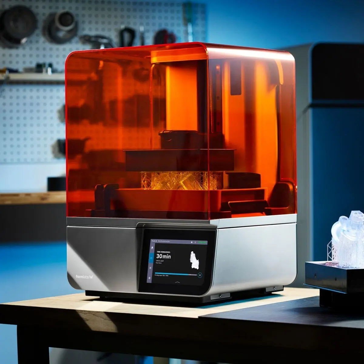
4.4 Prepare the printer.
Tricks for 3D Printing Textured Parts
Achieving the perfect look and feel on a part requires a bit of experimentation, but the rapid response of the Formlabs Texturing Engine makes it easy to iterate. Adjust the sliders to view effects and zoom in or out for a cohesive look at the part’s texture.
Different 3D printing processes have different requirements and capabilities for reproducing textured designs.
Stereolithography (SLA) 3D printing can replicate intricate and subdued textures, making it an optimal method for printing parts with a wide range of textures and patterns.
Selective laser sintering (SLS) 3D printing requires coarser, more exaggerated textures due to the slightly rougher surface finish, so adjustments should be made with this in mind.
Fused deposition molding (FDM) 3D printing can only resolve the most extreme textures on parts as layer lines are generally clearly visible on the surface, hiding or distorting the actual texture design.
Press ‘Print’
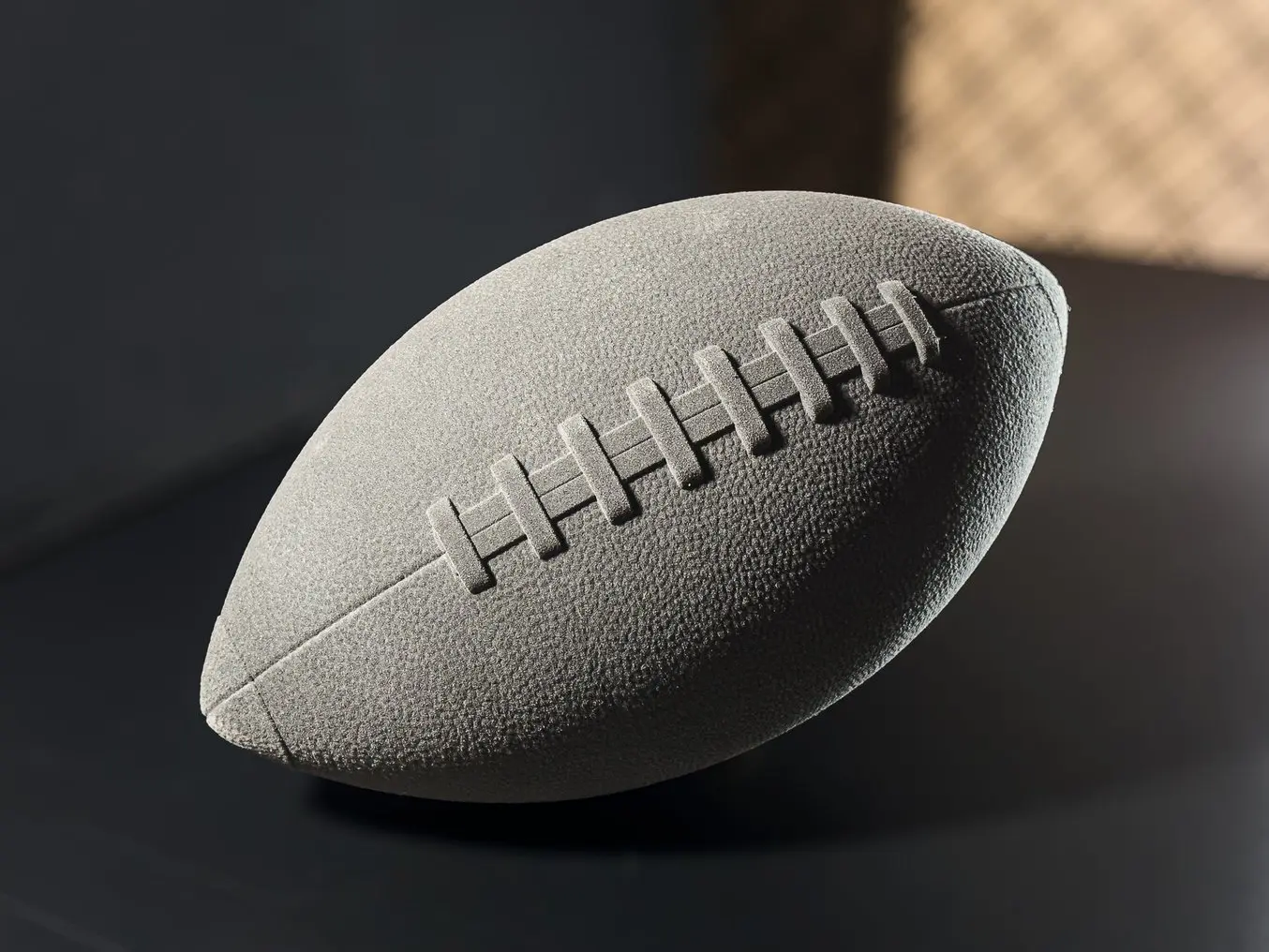
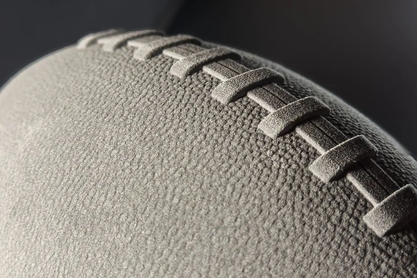
This textured football was printed with the Fuse 1+ 30W SLS 3D printer.
With the Formlabs Texture Engine, it’s possible to quickly apply surface textures and patterns to 3D models. Iterate quickly with this free, lightweight, web-based app and see how easy it is to add texture to 3D models.
Not sure which 3D printing solution fits your business best? Book a 1:1 consultation to compare options, evaluate ROI, try out test prints, and more.