
Manufactured items differ in size and dimensions from the original CAD model due to variations in the manufacturing processes. To optimally control and communicate these variations, engineers and manufacturers use a symbolic language called GD&T, short for Geometric Dimensioning and Tolerancing.
GD&T tells manufacturing partners and inspectors the allowable variation within the product assembly and standardizes how that variation is measured.
This guide walks through the GD&T system for streamlining communication about the design in both traditional and digital manufacturing.
Read on to learn about:
- The basic principles of GD&T
- An overview of GD&T symbols
- A case study that shows GD&T in use with Solidworks and a real-world product application
Book a Free Consultation
Get in touch with our 3D printing experts for a 1:1 consultation to find the right solution for your business, receive ROI analyses, test prints, and more.
What is GD&T?
GD&T, short for Geometric Dimensioning and Tolerancing, is a system for defining and communicating design intent and engineering tolerances that helps engineers and manufacturers optimally control variations in manufacturing processes.
Limitations of Tolerancing Before GD&T
Before GD&T, manufacturing features were specified by X-Y areas. For example, when drilling a mounting hole, the hole had to be within a specified X-Y area.
An accurate tolerancing specification, however, would define the position of the hole in relation to the intended position, the accepted area being a circle. X-Y tolerancing leaves a zone in which inspection would have produced a false negative because while the hole is not within the X-Y square, it would fall within the circumscribed circle.
Stanley Parker, an engineer who was developing naval weapons during World War II, noticed this failure in 1940. Driven by the need for cost-effective manufacturing and meeting deadlines, he worked out a new system through several publications. Once proven as a better operational method, the new system became a military standard in the 1950s.
Currently, the GD&T standard is defined by the American Society of Mechanical Engineers (ASME Y14.5-2018) for the USA and ISO 1101-2017 for the rest of the world. It concerns mostly the overall geometry of the product, while other standards describe specific features such as surface roughness, texture, and screw threads.
Introduction to 3D Printing With Desktop Stereolithography (SLA)
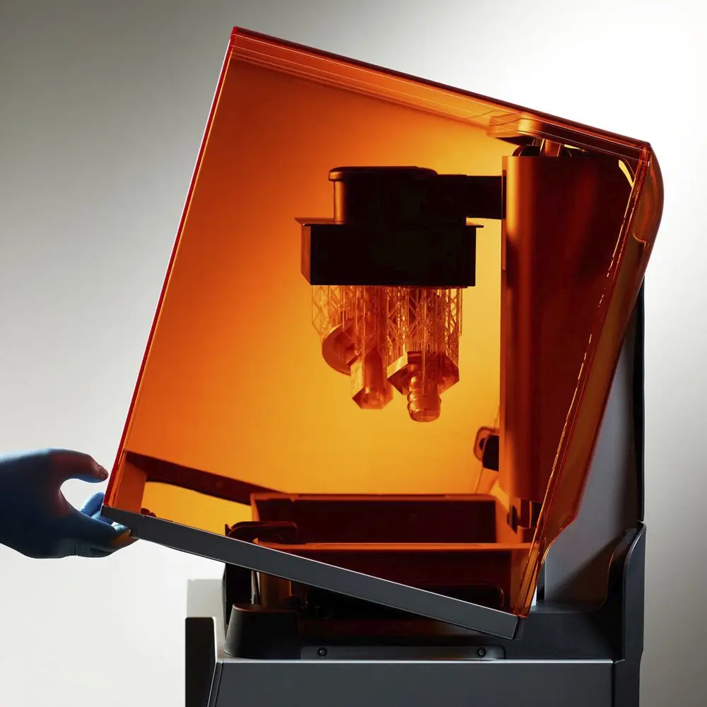
Looking for a 3D printer to realize your 3D models in high resolution? Download our white paper to learn how SLA printing works and why it's the most popular 3D printing process for creating models with incredible details.
Why Implement GD&T Processes?
GD&T is crucial for functional assemblies, multi-part products, or parts with complex functionality.
With functional assemblies, multi-part products, or parts with complex functionality, it is crucial that all components work well together. All relevant fits and features need to be specified in a way that impacts the manufacturing process and its related investments the least, while still guaranteeing functionality. Tightening tolerances by a factor two can raise the costs twofold or even more, due to higher reject rates and tooling changes. GD&T is the system that allows developers and inspectors to optimize functionality without increasing cost.
The most important benefit of GD&T is that the system describes the design intent rather than the resulting geometry itself. Like a vector or formula, it is not the actual object but a representation of it.
For example, a feature standing at 90 degrees to a base surface can be toleranced on its perpendicularity to that surface. This will define two planes spaced apart, that the center plane of the feature must fall within. Or, when drilling a hole, it makes the most sense to tolerance it in terms of alignment to other features.
Describing product geometry related to its intended functionality and manufacturing approach is ultimately simpler than having to describe everything in linear dimensions. It also provides a communication tool with manufacturing vendors, customers, as well as quality inspectors.
When performed well, GD&T even allows statistical process control (SPC), reducing product reject rates, assembly failures, and the effort needed for quality control, saving organizations substantial resources. As a result, multiple departments are able to work more in parallel because they have a shared vision and language for what they want to achieve.
How GD&T Works
Engineering drawings need to show the dimensions for all features of a part. Next to the dimensions, a tolerance value needs to be specified with the minimum and maximum acceptable limit. The tolerance is the difference between the minimum and maximum limit. For example, if we have a table that we would accept with a height between 750 mm and 780 mm, the tolerance would be 30 mm.
However, the tolerance for the table implies that we would accept a table that is 750 mm high on one side and 780 mm on the other, or has a waved surface with 30 mm variation. So to appropriately tolerance the product, we need a symbol communicating the design intent of a flat top surface. Therefore we have to include an additional flatness tolerance in addition to the overall height tolerance.
Parts with unpredictable variations and complex shapes require GD&T practices beyond simple plus-minus tolerancing.
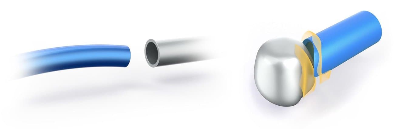
Similarly, a cylinder with a toleranced diameter will not necessarily fit into its hole if the cylinder gets slightly bent during the manufacturing process. Therefore it also needs a straightness control, which would be difficult to communicate with traditional plus-minus tolerancing. Or a tube that has to seamlessly match a complex surface that it’s welded to requires a surface profile control.
GD&T establishes a library of symbols to convey such design intents, which we discuss in the following section.

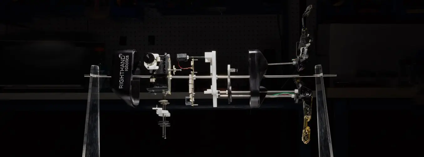
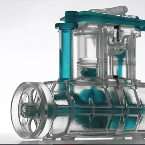
Dynamic assemblies such as this prosthetic hand require precise tolerancing.
The art of tolerancing means to specify just the right variations for all specific design features in order to maximize product approval rate within the limits of the manufacturing processes and depending on the part’s visual and functional purpose.
In the metric system, there are International Tolerance (IT) grades that can also be used to specify tolerances by means of symbols. The symbol 40H11, for example, means a 40 mm diameter hole with a loose running fit. The manufacturer then only needs to look up the basis table for hole features to derive the exact tolerance value.
Besides individual tolerances, engineers must take into account system-level effects. For example, when a part comes out with all dimensions at their maximum allowed value, does it still meet overall requirements such as product weight and wall thicknesses? This is called the Maximum Material Condition (MMC), while its counterpart is the Least Material Condition (LMC).
Tolerances also stack up. If we create a chain link where each hole has a 0.1 mm plus tolerance and each shaft a 0.1 mm negative tolerance, that means we will still accept a 20 mm length difference at 100 links. When installing repeated elements such as a perforated hole pattern, first position the pattern and then specify interrelated distances rather than referencing elements to a fixed edge or plane of the part.
The standards do not only pertain to designers and engineers but also to quality inspectors by informing them how to measure the dimensions and tolerances. Using specific tools such as digital micrometers and calipers, height gauges, surface plates, dial indicators, and a coordinate measuring machine (CMM) are important to tolerancing practice.
When measuring and defining a part, the geometry exists in a conceptual space called the Datum Reference Frame (DRF). This is comparable to the coordinate system at the origin of a space in 3D modeling programs. A datum is a point, line or plane that exists in the DRF and is used as a starting place for measuring. Make sure to define the datum features relevant to the functionality of your part. Unless you are mating features of one part to those of others in an assembly, you can often use a single datum. Always make sure that the primary datum has a reliable location to derive other measurements from, for example, where the final part will have little unpredictable variation.
GD&T Tolerancing Guidelines
An engineering drawing has to accurately convey the product without adding unnecessary complexity or restrictions. The following guidelines are helpful to consider:
-
Clarity of a drawing is the most important, even more so than its accuracy and completeness. To improve clarity, draw dimensions and tolerances outside of the part's boundaries and applied to visible lines in true profiles, employ a unidirectional reading direction, convey the function of the part, group and/or stagger dimensions, and make use of white space.
-
Always design for the loosest feasible tolerance to keep costs down.
-
Use a general tolerance defined at the bottom of the drawing for all dimensions of the part. Specific tighter or looser tolerances indicated in the drawing will then supersede the general tolerance.
-
Tolerance functional features and their interrelations first, then move on to the rest of the part.
-
Whenever possible, leave GD&T work to the manufacturing experts and do not describe manufacturing processes in the engineering drawing.
-
Do not specify a 90-degree angle since it is assumed.
-
Dimensions and tolerances are valid at 20 °C / 101.3 kPa unless stated otherwise.
GD&T Symbols
GD&T is feature-based, with each feature specified by different controls. GD&T symbols fall into five groups:
-
Form controls specify the shape of features, including:
-
Straightness is divided into line element straightness and axis straightness.
-
Flatness means straightness in multiple dimensions, measured between the highest and lowest points on a surface.
-
Circularity or roundness can be described as straightness bent into a circle.
-
Cylindricity is basically flatness bent into a barrel. It includes straightness, roundness, and taper, which makes it expensive to inspect.
-
-
Profile controls describe the three-dimensional tolerance zone around a surface:
-
Line Profile compares a two-dimensional cross-section to an ideal shape. The tolerance zone is defined by two offset curves unless otherwise specified.
-
Surface Profile creates through two offset surfaces between which the feature surface must fall. This is a complex control typically measured with a CMM.
-
-
Orientation controls concern dimensions that vary at angles, including:
-
Angularity is flatness at an angle to a datum and is also determined through two reference planes spaced the tolerance value apart.
-
Perpendicularity means flatness at 90 degrees to a datum. It specifies two perfect planes the feature plane must lie in between.
-
Parallelism means straightness at a distance. Parallelism for axes can be defined by defining a cylindrical tolerance zone by placing a diameter symbol in front of the tolerance value.
-
-
Location controls define feature locations using linear dimensions:
-
Position is the location of features relative to one another or to datums and is the most used control.
-
Concentricity compares the location of a feature axis to the datum axis.
-
Symmetry ensures that non-cylindrical parts are similar across a datum plane. This is a complex control typically measured with a CMM.
-
-
Runout controls define the amount by which a particular feature can vary with respect to the datums:
-
Circular Runout is used when there is a need to account for many different errors, such as ball-bearing mounted parts. During inspection, the part is rotated on a spindle to measure the variation or ‘wobble’ around the rotational axis.
-
Total Runout is measured on multiple points of a surface, not just describing the runout of a circular feature but of an entire surface. This controls straightness, profile, angularity, and other variations.
-
GD&T Symbols Overview
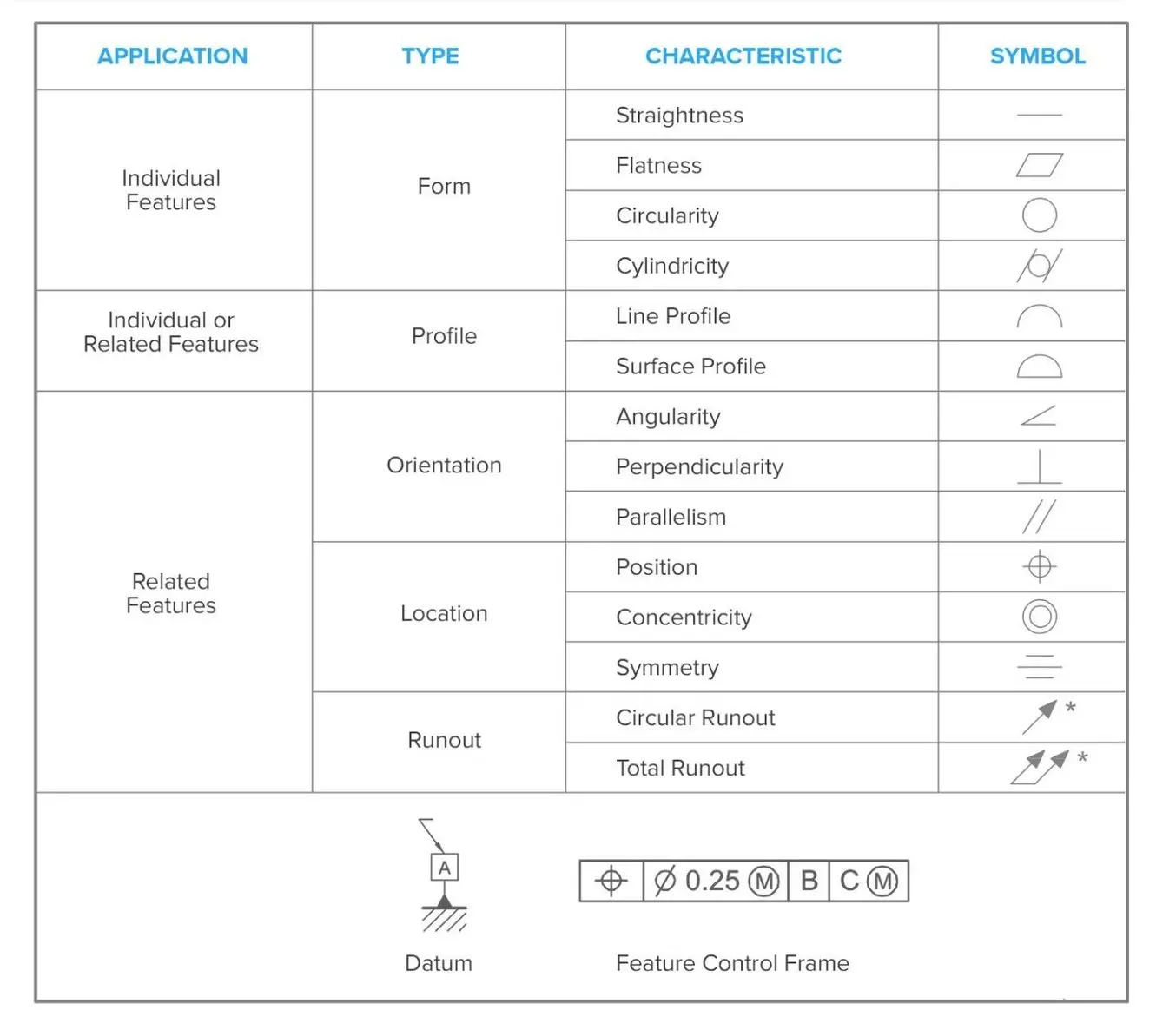
Both ANSI and ISO standards use these common symbols for tolerancing controls.
Feature Control Frame (FCF)
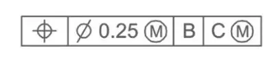
The Feature Control Frame is the notation to add controls to the drawing. The leftmost compartment contains the geometric characteristic. In the example above, it is a location control but it can contain any of the control symbols. The first symbol in the second compartment indicates the shape of the tolerance zone. In this example, it is a diameter as opposed to a linear dimension. The number indicates the allowed tolerance.
Next to the tolerance box, there are separate boxes for each datum feature that the control refers to. Here, the location will be measured related to datum B and C. Next to the tolerance or a datum feature is an optional encircled letter, the feature modifier.
The following possibilities can occur:
-
M means that the tolerance applies in the Maximum Material Condition (MMC)
-
L means that the tolerance applies in the Least Material Condition (LMC)
-
U indicates an unequal bilateral tolerance, i.e. for a 1 mm tolerance it may specify it as minus 0.20 and plus 0.80.
-
P means that the tolerance is measured in a Projected Tolerance Zone at a specified distance from the datum.
-
No symbol installs the tolerance regardless of feature size (RFS)
For this example, if the part is not in MMC, a bonus tolerance can be added proportionally to the deviation from MMC. So if a part is at 90% MMC, the tolerance will also loosen by 10%.
Tolerancing in 3D Printing
Many product designers and engineers use 3D printing during product development for rapid prototyping and rapid tooling to produce cost-effective prototypes and custom parts that would otherwise require significant investment in tooling.
Tolerancing in 3D printing differs from traditional manufacturing tools because 3D printing is a single automated process. Tighter tolerances may require more effort in the design stage, but can yield significant time and costs savings in prototyping and production.
Optimizing Design for Functional 3D Printed Assemblies
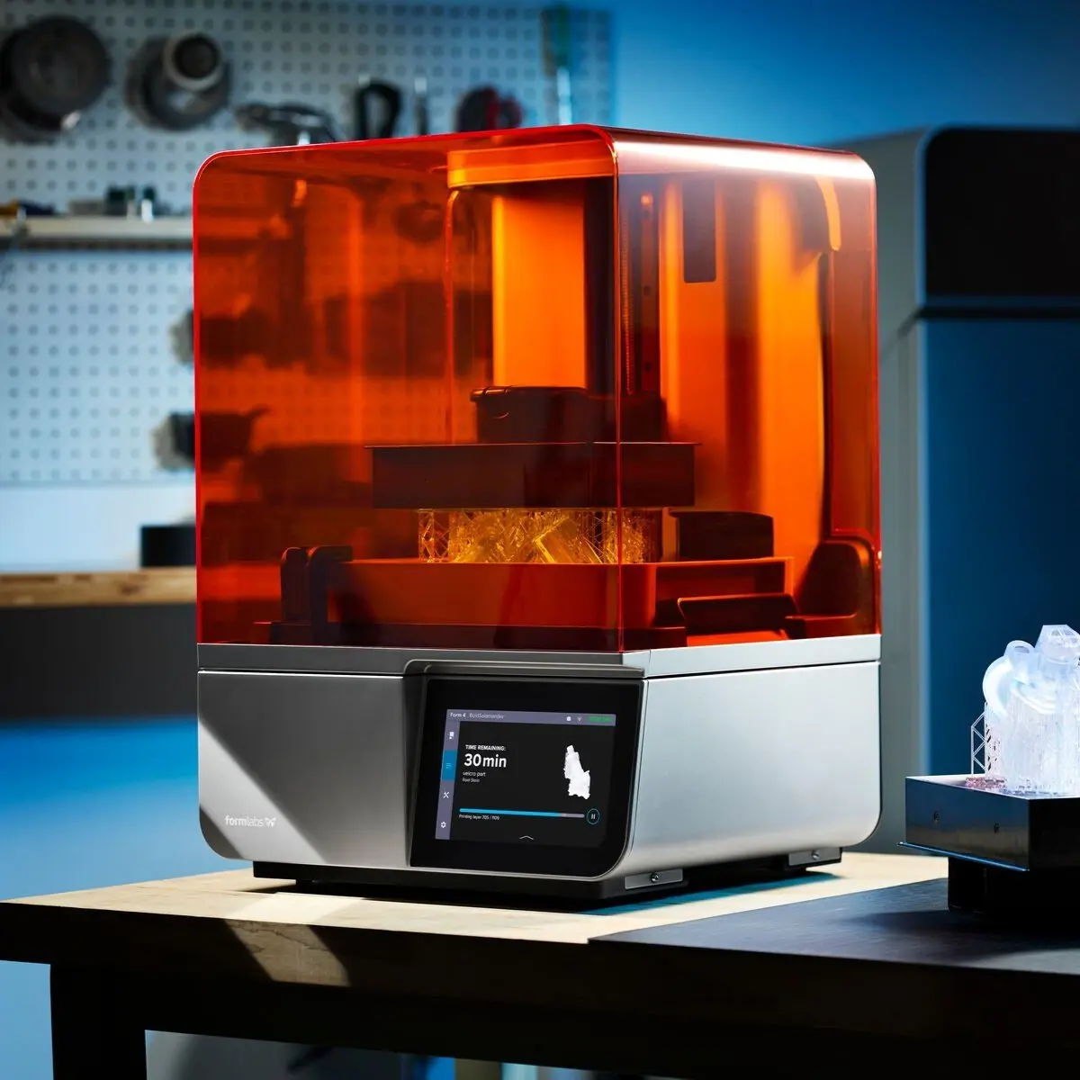
Stereolithography (SLA) 3D printers such as the Formlabs Form 3+ have high accuracy and precision, and offer a wide range of engineering materials. Download our white paper for specific recommended design tolerances.
GD&T Example Case Study
Most CAD tools aimed at mechanical engineering such as SolidWorks, Autodesk Fusion 360, AutoCAD, SolidEdge, FreeCAD, CATIA, NX, Creo, and Inventor offer GD&T integration when creating engineering drawings. However, designers still have to install tolerances manually, taking into account the possible deviations that occur during the manufacturing process. In the following case study, we show an example of GD&T in use in SolidWorks.
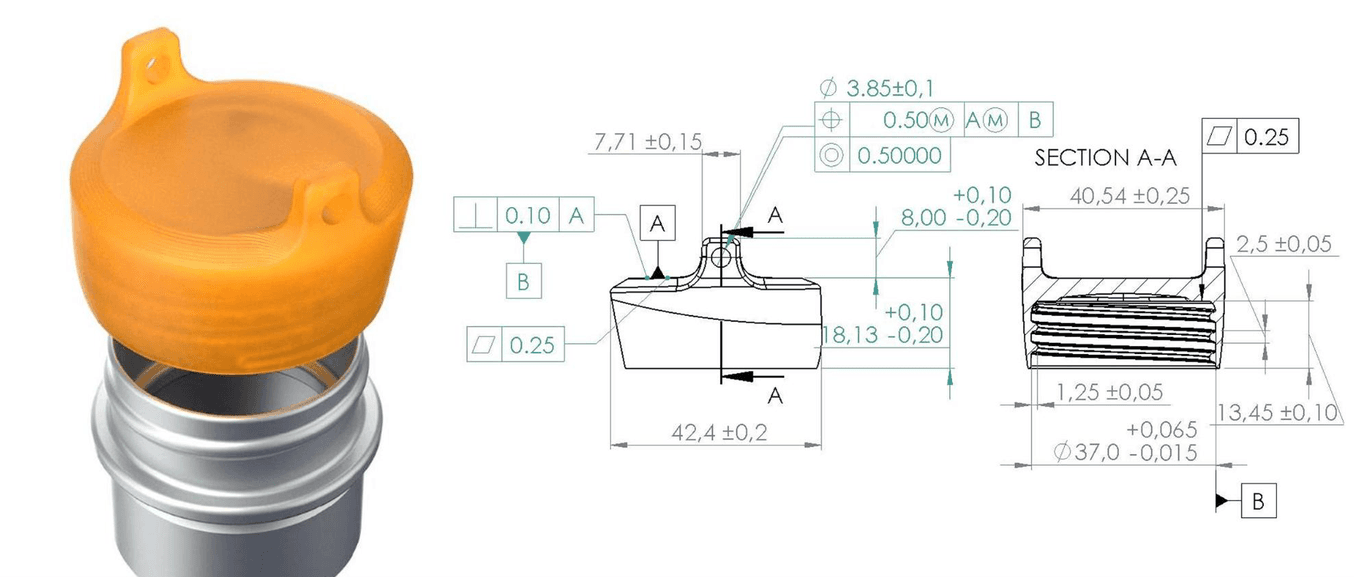
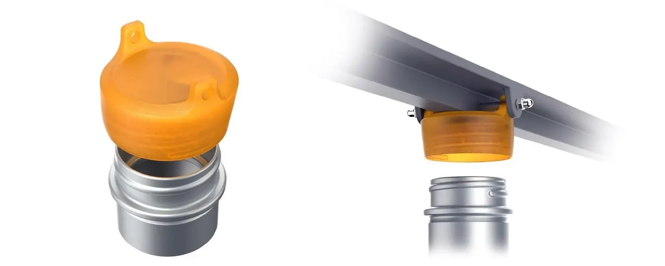
This specific project aims to produce 50,000 bottle caps through injection molding. We want to control the feel and force with which the caps will fit onto the bottle and therefore require good tolerancing specification. We want to prevent that some caps are larger in outer diameter than the bottle, while others are smaller, and retain a consistent running fit instead.
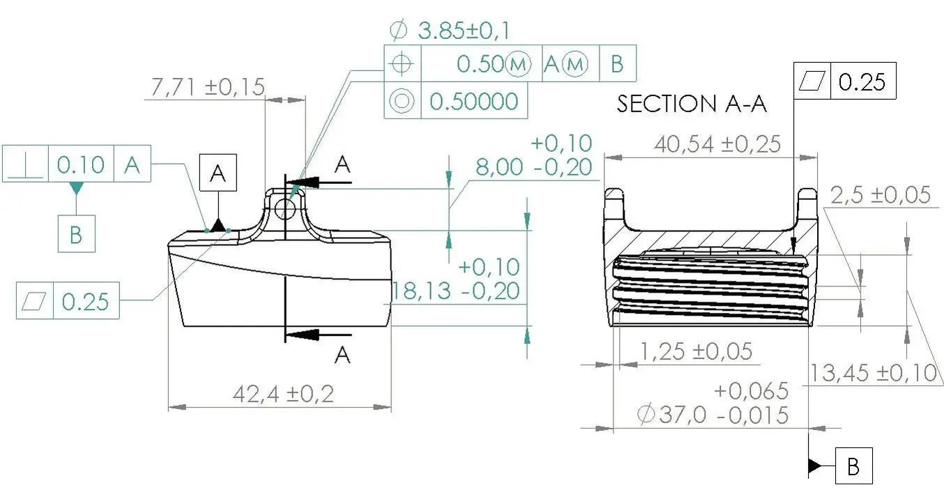
The bottle’s thread has an outer diameter of 36.95 +/- 0.010 mm. That means the limits of the cap’s inner diameter are 36.985 and 37.065 mm, with a mean value of 37.0 mm.
The cap also has specific hole connections to an axle that is mounted underneath a flat surface. This allows the bottle to be opened with one hand while it hangs underneath the surface of a storage cabinet. The axle is a standard OEM stainless steel component with a 4mm diameter and 0.13mm (0.005”) tolerance. For a snug connection, we require a force fit with an allowance between -0.0375 and 0.0125 mm. Here we find a range of 3.99 to 4.01 mm for the hole diameter that results in a force fit for all axle sizes. Because this is such a narrow range we decide to specify the hole at 3.85 mm then drill it to an exact 4.00 mm which also controls concentricity of the two holes.
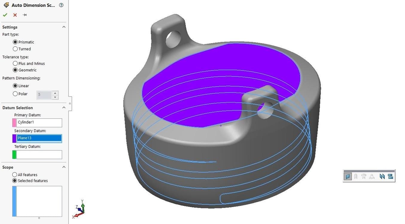
To control our dimensions properly, we need to make use of a datum. A datum needs to represent mating features and function of the assembly, plus it needs to be stable, repeatable, and accessible. In this case, the mating of the cap and bottleneck are most important, so we choose the cap’s inner cylindrical surface as the primary datum. The secondary function is the mating with the mounting surface, so we pick the flat top of the cap as the secondary datum.
After considering the requirement, implementing GD&T tolerancing in Solidworks works as follows. Indicate the datums in DimXpert > Auto Dimension Scheme and select the Geometric option as opposed to Plus/Minus tolerancing. Then select the datums and features to control based on the datums. With the Dimension Scheme completed, add individual Geometric Tolerances and GD&T symbols. The software automatically generates dimensions for features-of-size (FOS), such as holes and bosses. Make sure to select ‘bilateral’ or ‘limit’ as tolerance type for features where the plus and minus limit are unequal.
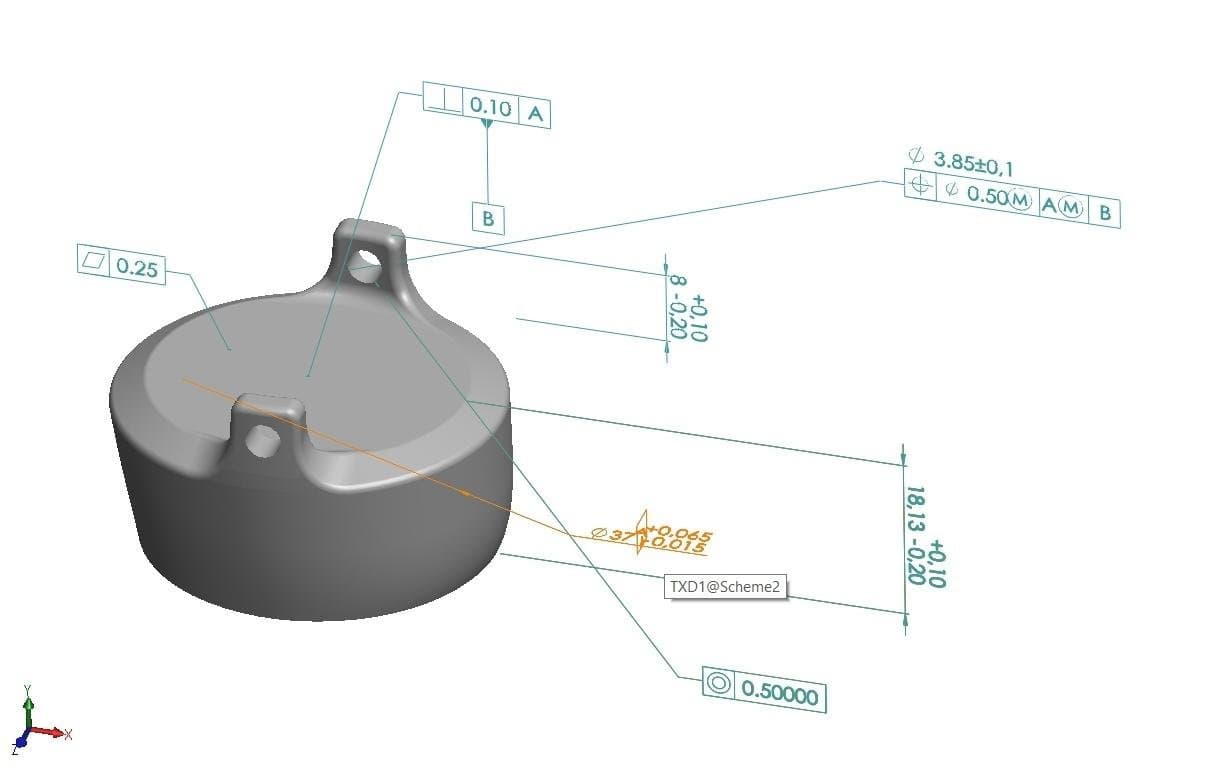
To import these tolerances into an engineering drawing, first, check the FeatureManager for which planes are used in the ‘Annotations’ folder. When importing the views from these planes into a drawing, check ‘Import annotations’ and ‘DimXpert annotations’. Adding an appropriate section view will greatly clarify the drawing.
Request a Free Sample Part
See and feel Formlabs quality firsthand. We’ll ship a free sample part to your office.
Prototype and Manufacture Parts Rapidly With 3D Printing
In this guide, we have discussed the system of Geometric Dimensioning and Tolerancing (GD&T), which brings tremendous benefits for designers and engineers working on complex products where dimensions need to be tightly controlled. We have seen how GD&T conveys not only linear dimensions but also design intent, which helps communicate the engineering design more clearly to project stakeholders.
With just over a dozen symbols, the datum feature, and feature control frame, it is possible to highly enrich production drawings and ensure that engineering fits remain consistent across product assemblies. GD&T also invites developers to think about how to optimally tolerance their parts for the chosen manufacturing process, since different production techniques bring along different characteristic deviations.
Companies across aerospace, automotive, defense, consumer goods, medical, and more are adopting digital manufacturing tools to take steps towards the promise of Industry 4.0. 3D printing is a catalyst for efficiency, giving staff from production engineer to machinist the tools to tighten supply chains, improve production, and get to market faster—saving hundreds of thousands of dollars and weeks to months of time along the way.
Learn more about how leading manufacturers like Ford, General Electric, and Dyson leverage 3D printing to save money and shorten lead times from design to production.
Not sure which 3D printing solution fits your business best? Book a 1:1 consultation to compare options, evaluate ROI, try out test prints, and more.