
Required Supplies:
Formlabs:
- Mixer drive assembly
- 3 mm ball-end hex driver
- 3 mm hex driver (included in the Form 4L tool caddy)
- 2.5 mm hex driver (included in the Form 4L tool caddy)
- 2 mm hex driver (included in the Form 4L tool caddy)
Third-party:

The mixer drive assembly controls the mixer on the printer, which is important to mix the resin and detect debris. The assembly is located behind the printer’s touchscreen. Any damage to the mixer drive assembly’s components may prevent the printer from functioning properly.
Use this guide to replace the mixer drive assembly.
Required Supplies:
Formlabs:
Third-party:
Estimated time: 1 hour
Preparing the workspace
Overview: Prepare the printer and workspace for replacing the mixer drive assembly.
Step 1: Remove the build platform
Remove the build platform first to avoid dripping resin onto the Light Processing Unit (LPU).
Step 2: Remove the resin cartridges
Remove the resin cartridges and close the vent caps to prevent resin from dripping off of the bite valves and into the printer.
Step 3: Remove and store the resin tank and mixer
Unlatch the mixer and resin tank. Remove the resin tank and cover it with its lid. Set the tank aside on a clean, flat surface.
NOTICE:
Wear gloves and hold the resin tank by the tank grips on either side to avoid contamination or damage to the underside of the tank.
Step 4: Prepare the workspace
Clear a workspace around your printer. Ensure that the workspace is well-ventilated and free of dust.
Step 5: Clean the printer
WARNING:
Resin may cause skin irritation or an allergic skin reaction. Wear gloves when handling liquid resin or resin-coated surfaces. Wash skin with plenty of soap and water.
Open the printer cover and clean any resin pooled on and around the LPU with non-abrasive wipes. Dampen the wipes with isopropyl alcohol if necessary to fully remove the resin.
DANGER:
Fire hazard. IPA is flammable. Keep containers closed, and keep out of the reach of children.
Step 6: Unplug the printer
Disconnect the power cable before continuing with maintenance. Do not perform maintenance on the printer while it is connected to power. Wait five minutes after disconnecting the printer from power before proceeding.
Removing the side panels
Overview: Remove the side panels to access the touchscreen assembly.
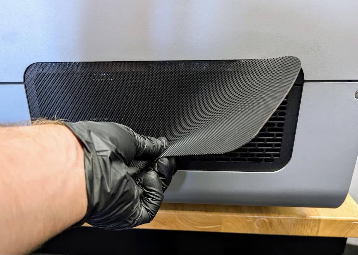
Remove the mesh filter from the right of the printer.
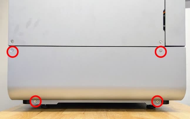
Use a 2.5 mm hex driver to remove the four screws that secure the lower right side panel to the printer. Remove the panel and set it aside.

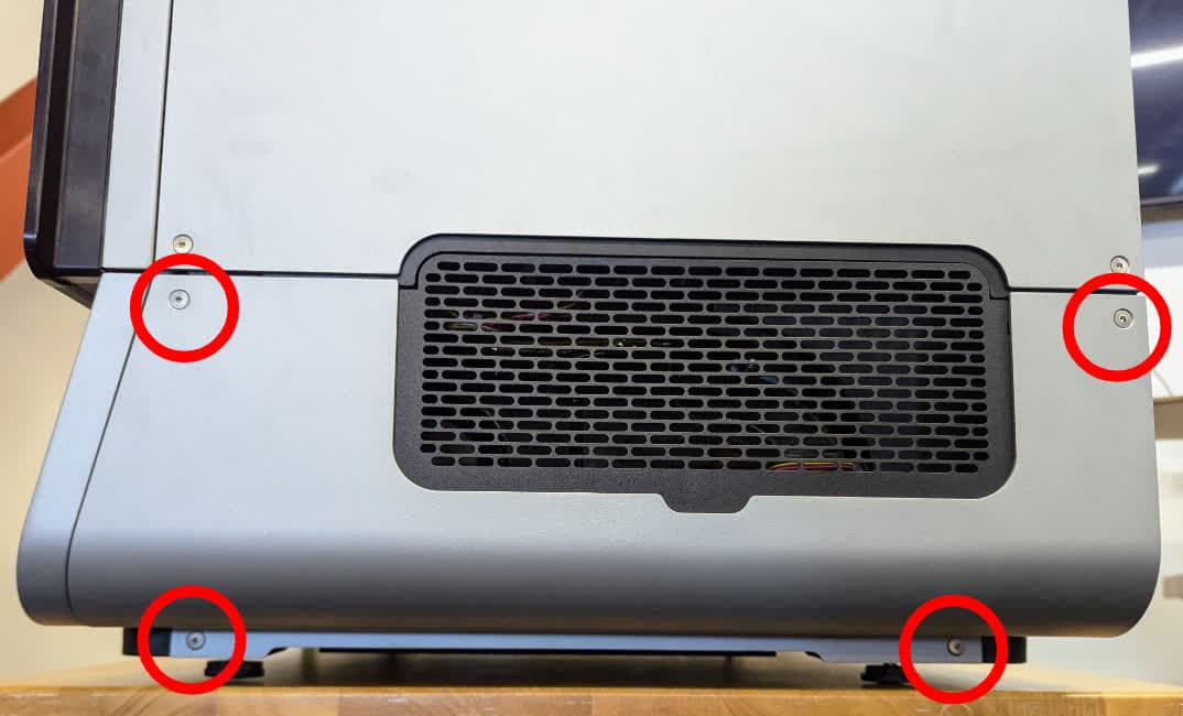
Use a 2.5 mm hex driver to remove the four screws that secure the lower left side panel to the printer. Remove the panel and set it aside.
Removing the touchscreen assembly
Overview: Remove the touchscreen to access the mixer drive assembly.
Step 1: Remove the touchscreen assembly mounting screws
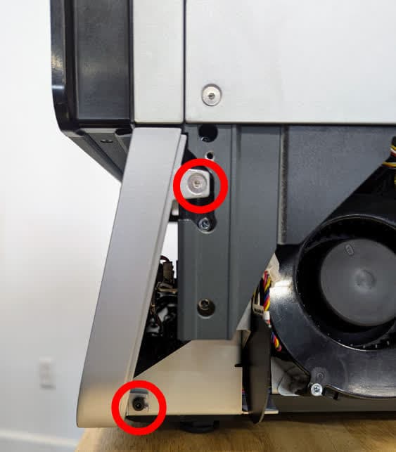

Position the Form 4L so that there is at least 6 inches (150 mm) of table space in front of the printer. Starting on the right side of the machine, use a 2.5 mm hex driver to remove the countersunk screw located on the upper part of the touchscreen assembly. Use a 3 mm hex driver to remove the one screw located on the lower part of the touchscreen assembly.
On the left side of the machine, use a 3 mm hex driver to remove the three screws that secure the left side of the touchscreen assembly to the printer. Set the five screws aside.
Step 2: Position the printer
With a second person, position the Form 4L near the front edge of the workspace to access the bottom screws.
Step 3: Remove the bottom front panel retention screws
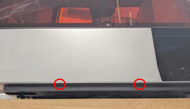
Use a 1.5 mm hex driver to remove the two screws securing the front panel to the bottom of the printer.
Step 4: Reposition the printer
With a second person, position the Form 4L so that there is at least 6 inches (150 mm) of workspace in front of the printer.
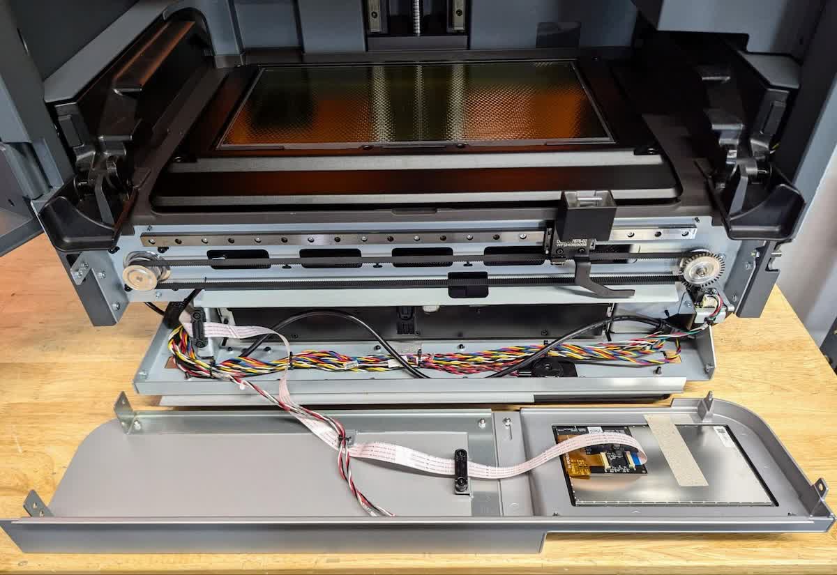
Rotate the touchscreen assembly so it rests facedown in front of the printer. Avoid straining the cables.
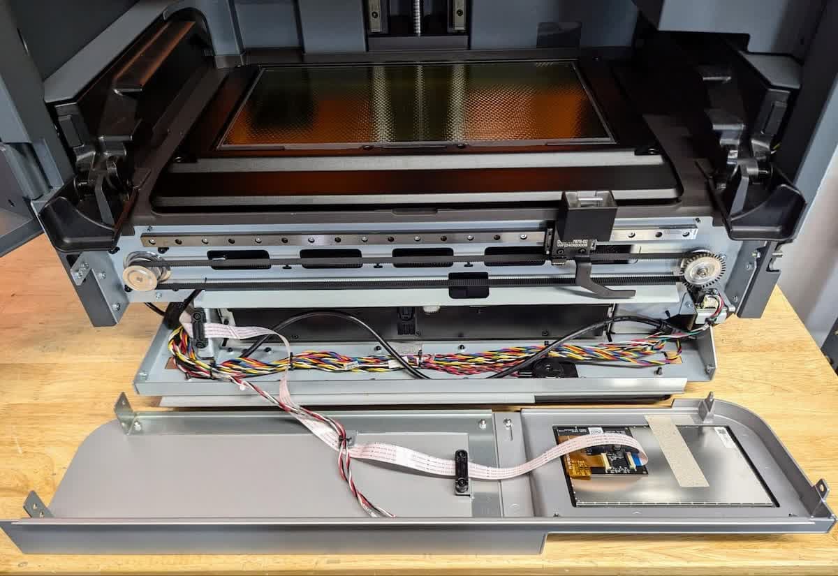
Replacing the mixer drive assembly
Overview: After removing the touchscreen assembly, replace the mixer drive assembly.
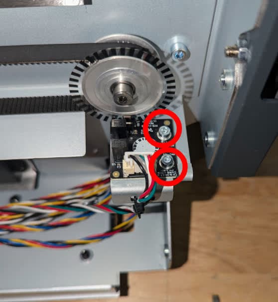
Locate the mixer encoder board, positioned under the pulley at the right end of the mixer belt. Release the mixer encoder board cable by pressing on the plastic tab, then unplug the cable from the mixer encoder board. Use a 2.5 mm hex driver to remove the two screws that secure the mixer encoder board to the printer. Set the screws aside.
Take care when unplugging the cable to avoid damage. Once the plastic tab is pressed, the cable will easily slide from the connector. Do not pull on the wires.
Step 2: Install the replacement mixer encoder board
Remove the replacement mixer encoder board from its packaging. Place the board on its mount, aligning the screw holes in the board with those in the printer frame. Thread one screw into both of the screw holes. Use a 2.5 mm hex driver to tighten the screws until snug. Reconnect the mixer encoder board cable.
NOTE:
If the mixer encoder board is the only component that needs to be replaced, skip to Reinstalling the touchscreen assembly.
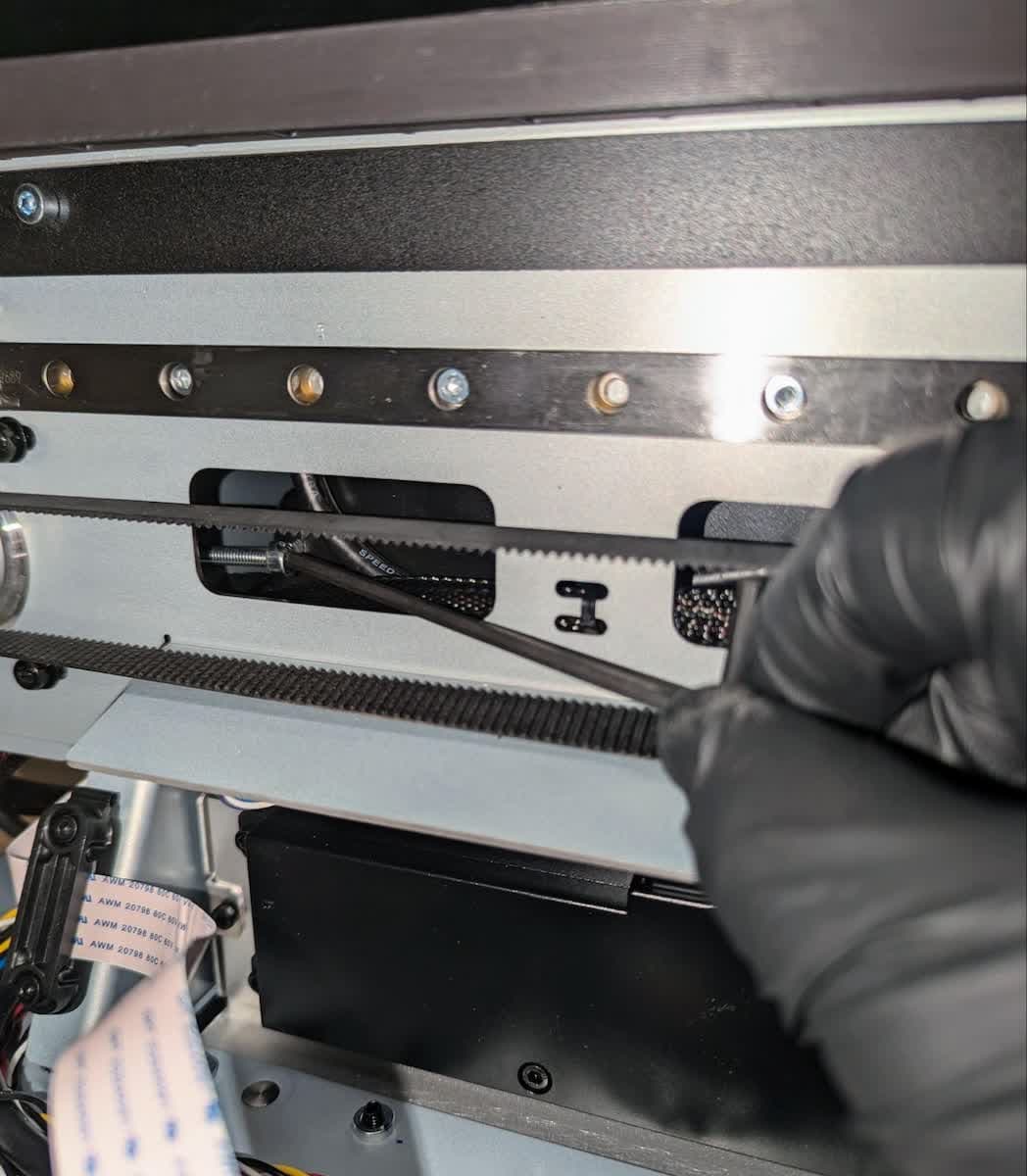
Use a 3 mm ball-end hex driver to loosen the belt tensioning bolt that is accessible through the chassis slot to the right of the mixer drive motor. Do not fully remove the bolt.
Step 4: Remove the mixer drive motor

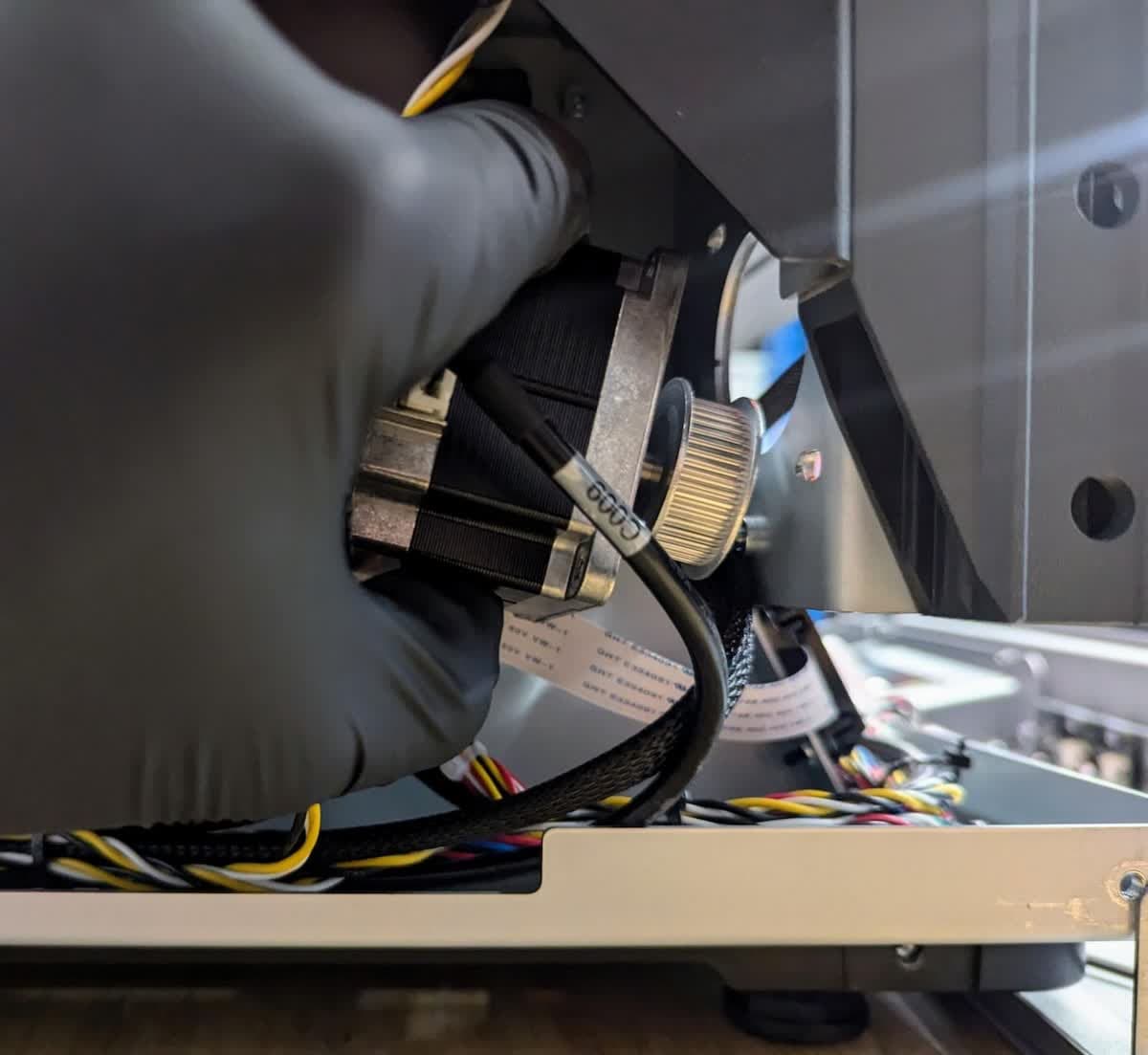
Use a 3 mm hex driver to remove the four screws and washers that secure the mixer motor to the printer. Set the screws and washers aside. Slide the motor out of its bracket. Release the motor cable by pressing on the plastic tab, then unplug the cable from the motor.
Take care when unplugging the cable to avoid damage. Once the plastic tab is pressed, the cable will easily slide from the connector. Do not pull on the wires.
Slide the mixer base so that it is positioned above the cutout in the middle of the printer chassis. Use a 2 mm hex driver to remove the four screws that secure the belt clamp to the mixer base. Set the screws and clamp aside.
Use a 2.5 mm hex driver to remove the four screws and washers that secure the mixer base to the linear bearing. Set the screws and washers aside.
Remove the mixer belt from the printer.
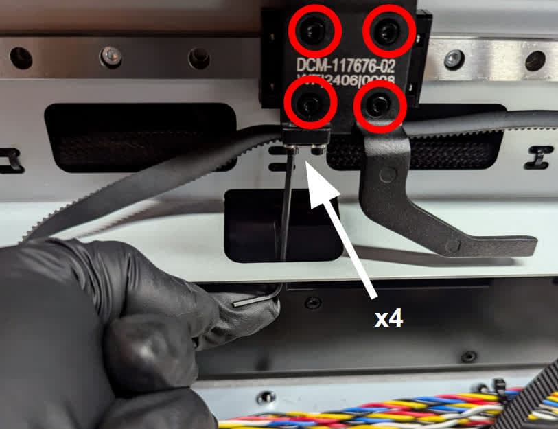
Step 6: Install the replacement mixer base
Mount the replacement mixer base onto the linear bearing so that the screw holes on the mixer base and the printer align. Thread the four mixer base retention screws and washers into their screw holes on the mounted mixer base. Using a 2.5 mm hex driver, tighten the retention screws until finger tight. Do not overtighten the screws.
Step 7: Install the replacement mixer belt
With the teeth on the replacement belt facing inward, align the belt between the belt clamp screw holes in the mixer base. Place the new belt clamp over the belt teeth, aligning its screw holes with those in the mixer base. Ensure that the teeth on the belt protrude through the slots in the clamp. Thread one belt clamp retention screw into each of the four screw holes, then use a 2 mm hex driver to tighten until snug.
Use a 3 mm hex driver to remove the shoulder bolt that secures the mixer idler pulley and encoder wheel assembly to the printer. Mount and secure the replacement pulley in its place. During installation, loop the belt onto the idler pulley.
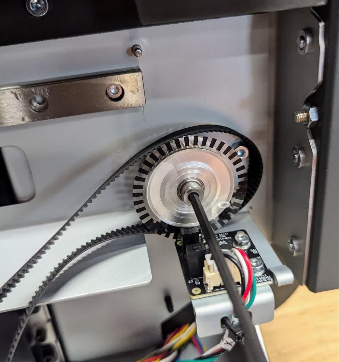
Step 9: Loosely install the mixer drive motor
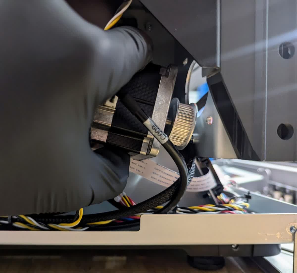
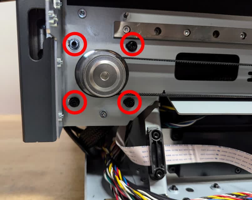
Connect the motor cable to the replacement mixer drive motor. The plastic tab should click into place to secure the connection. Slide the motor into the bracket from the inside of the printer frame. Use a 3 mm hex driver to loosely install the four screws and washers that secure the mixer motor to the printer.
Tensioning the mixer belt
Overview: After installing the mixer drive motor, tension the mixer belt.
NOTICE:
This step should be performed in a location free of HVAC fans, machines, and other background noise to complete this step. This is important to ensure that the belt tension is set accurately. If the tuner does not settle on a frequency or the reported frequency does not change after modifying the belt tension, relocate to a quieter space.
Step 1: Position the belt
Loop the belt around the motor pulley. Move the mixer body all the way to the left of the machine.
Step 2: Download an audio tuner app
Install an audio tuner smartphone app on a smartphone. The following are recommended:
Step 3: Tension the belt
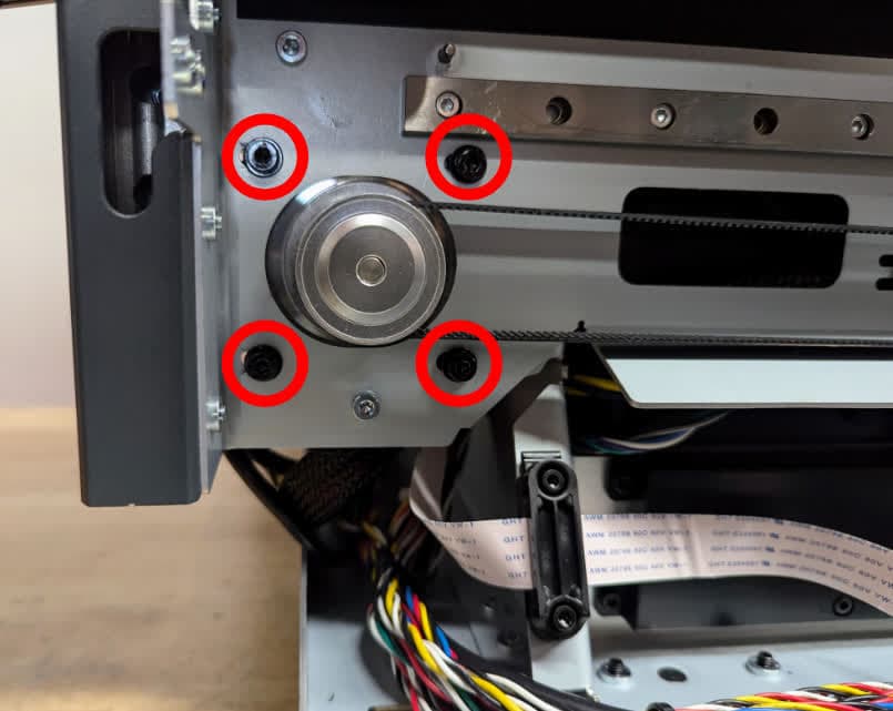

Ensure that the four screws that secure the mixer motor to the printer are loose. Use a 3 mm hex driver to tighten the tensioning screw. Clockwise rotation increases tension and counterclockwise rotation decreases tension.
Use a 2.5 mm hex driver to tighten the four screws that secure the mixer motor to the printer and set the belt tension.
Step 4: Measure the belt tension
Open the tuner app on the smartphone. Hold the bottom of the smartphone near the middle of the mixer belt without touching the belt. Pluck the upper span of the belt with a finger and note the frequency measured by the tuner app. Repeat until you are able to measure consistent readings. Make a note of the readings for later use. If the tuner does not settle on a frequency, relocate to a quieter space.
A properly-tensioned mixer belt should produce a sound between 43–51 Hz when plucked.
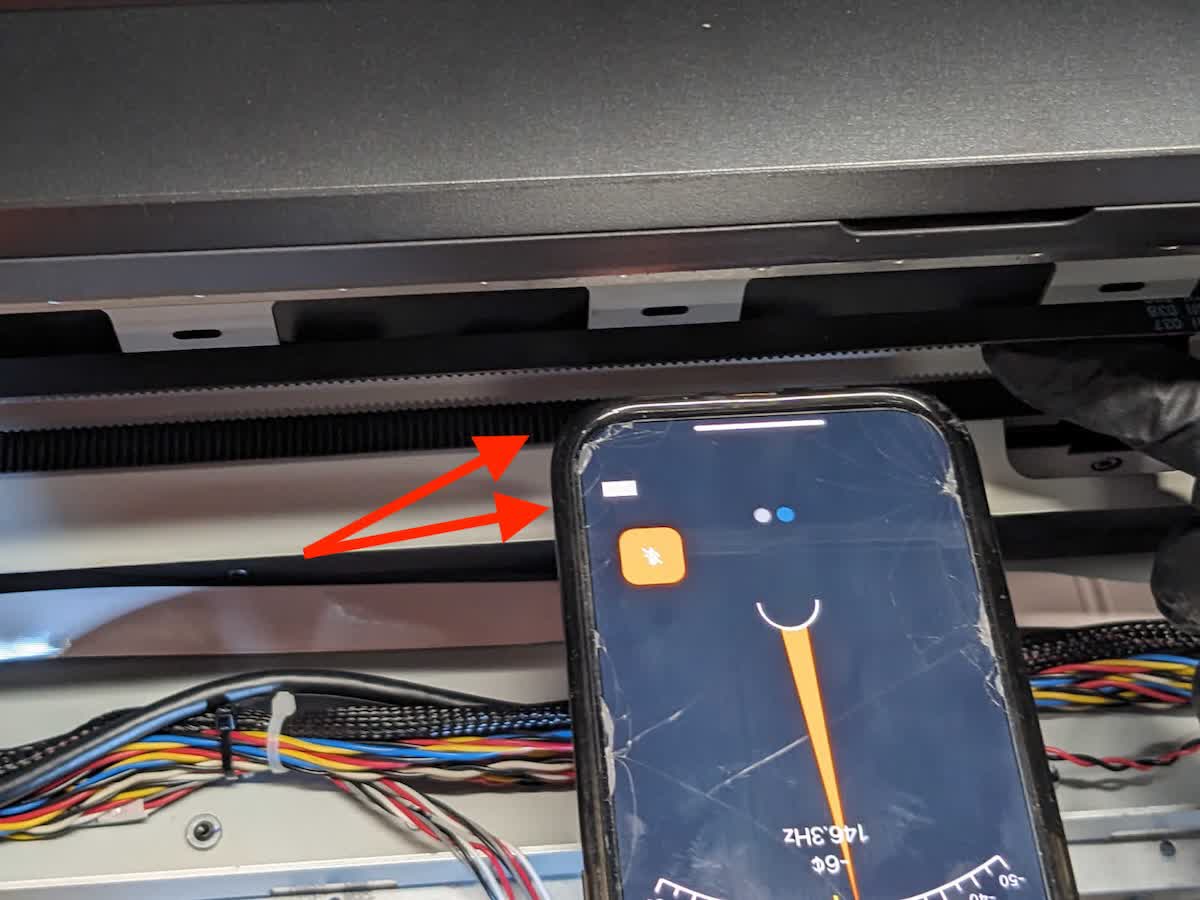
Note:
Make sure that the belt does not come into contact with the smartphone during frequency measurement.
Step 5: Adjust the belt tension
Repeat steps 3–4 until you measure a frequency between 43–51 Hertz.
Reinstalling the touchscreen assembly
Overview: After replacing the mixer drive assembly, reinstall the touchscreen assembly.
Step 1: Install the touchscreen assembly
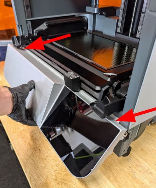
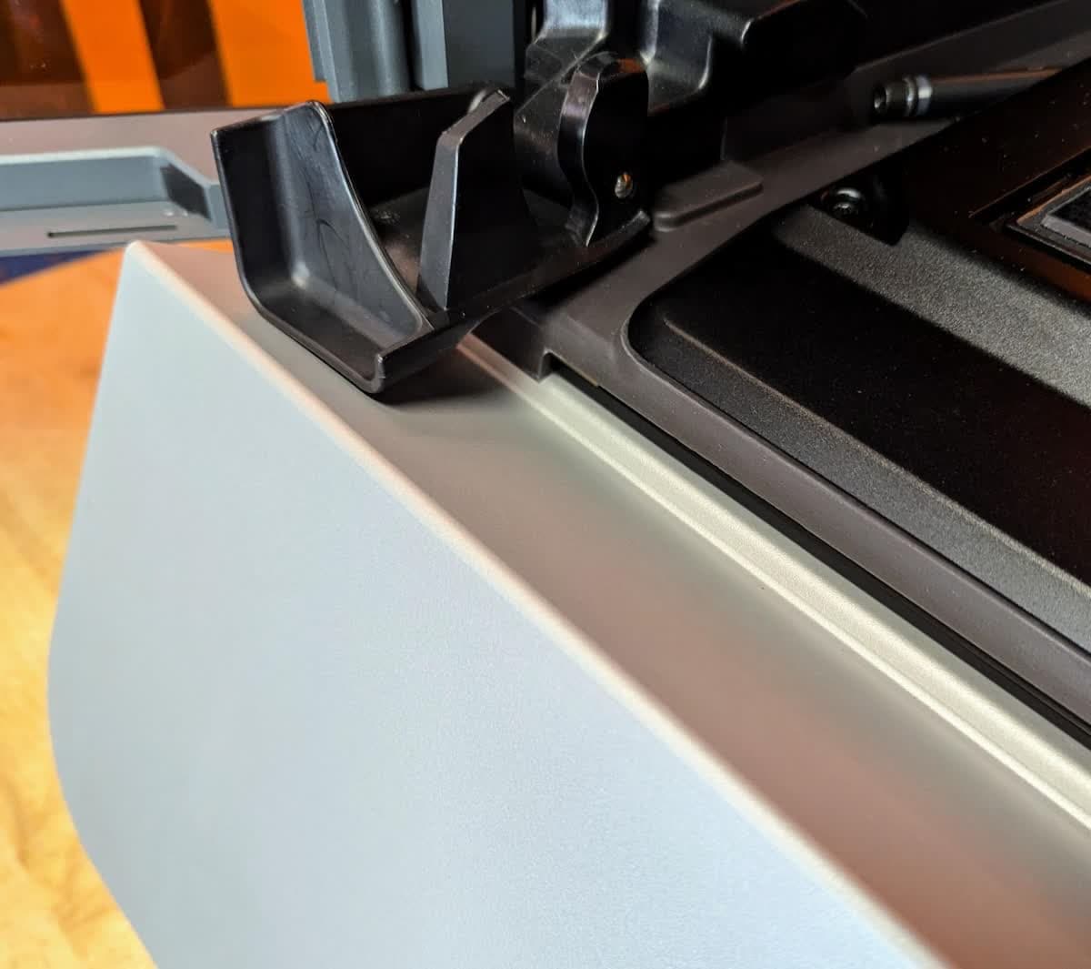
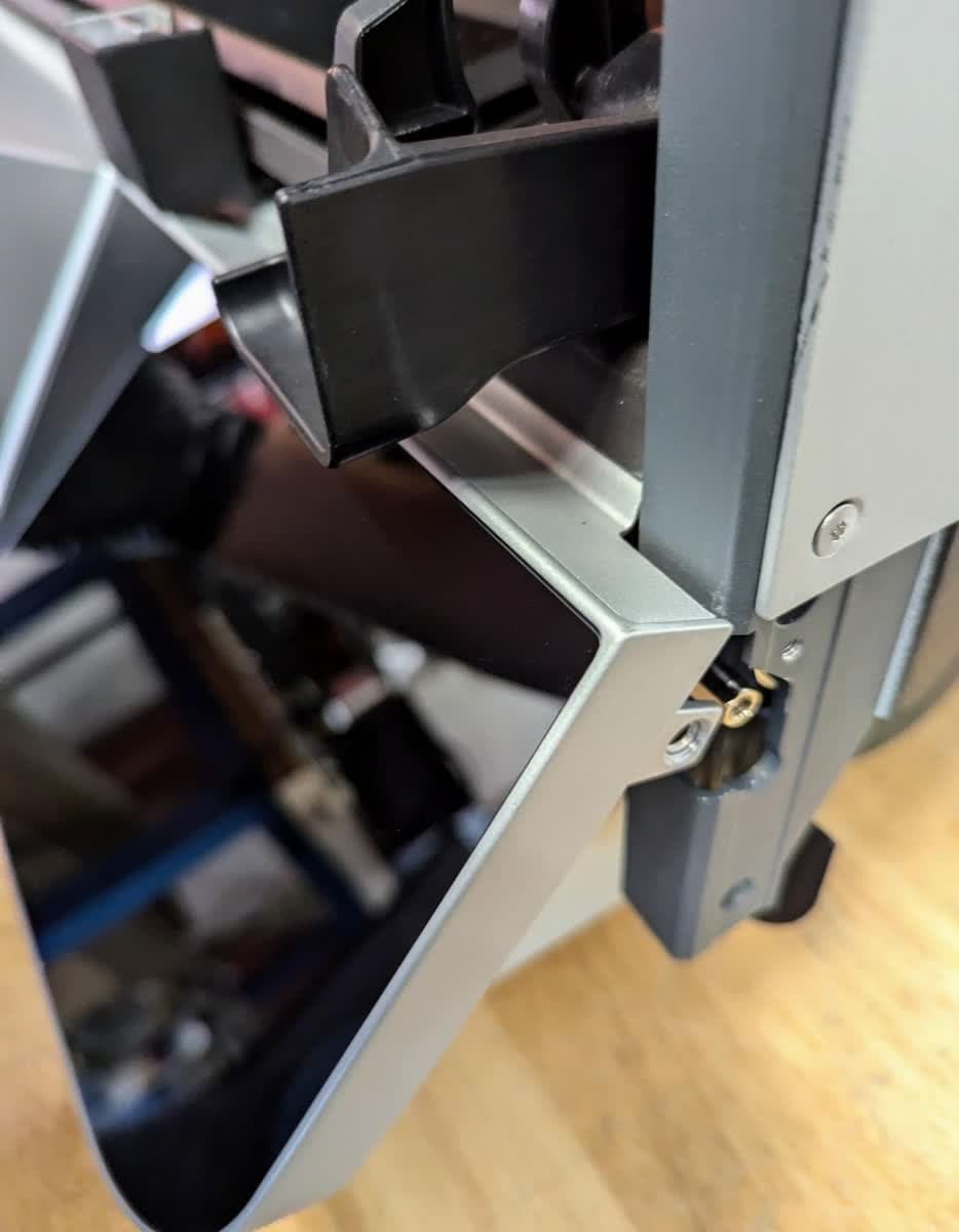
Angle the touchscreen assembly towards the printer and slide the left and right edges under the bezel on the printer. Rotate the touchscreen assembly down into position. Make sure that the screw tabs on the sides of the touchscreen assembly are positioned outside of the printer tabs.
Step 2: Install the touchscreen assembly mounting screws
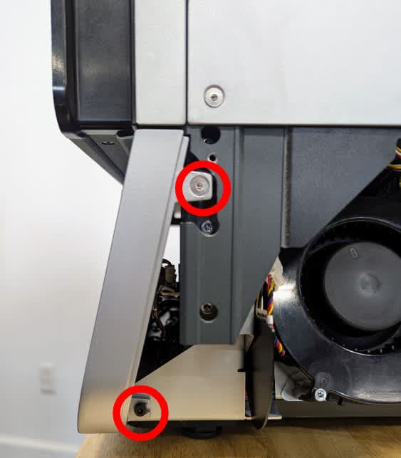
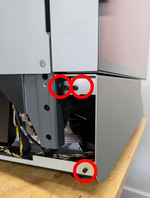
Starting on the right side of the machine, use a 2.5 mm hex driver to install the countersunk screw located on the upper part of the touchscreen assembly. Use a 3 mm hex driver to install the one screw located on the lower part of the touchscreen assembly. On the left side of the machine, use a 3 mm hex driver to install the three screws that secure the left side of the touchscreen assembly to the printer.
Step 3: Position the printer
With a second person, position the Form 4L near the front edge of the workspace to access the bottom screws.
Step 4: Secure the bottom front panel retention screws
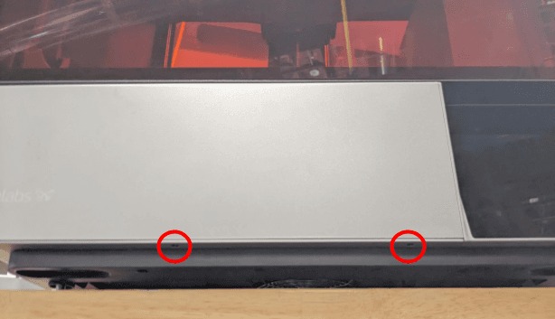
Using a 1.5 mm hex driver, secure the bottom front panel retention screws to the printer. Tighten the screws until finger tight.
Reinstall the side panels
Overview: After reinstalling the touchscreen assembly, reinstall the side panels.
Mount the lower left side panel on the printer, aligning the screw holes in the panel with the corresponding holes in the printer frame. Use a 2.5 mm hex driver to install the four screws that secure the lower left side panel to the printer.
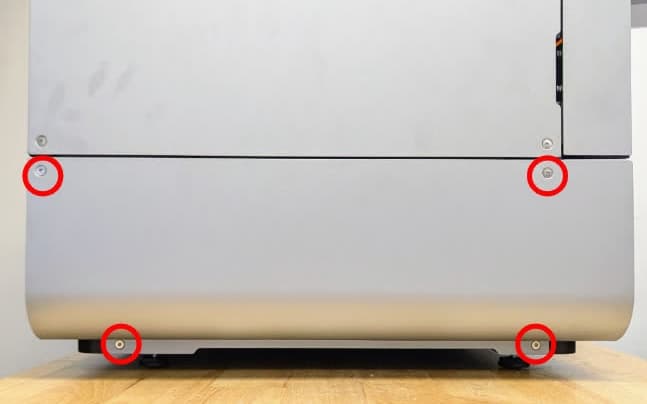
Mount the lower right side panel on the printer, aligning the screw holes in the panel with the corresponding holes in the printer frame. Use a 2.5 mm hex driver to install the four screws that secure the lower right side panel to the printer.
Step 3: Reinstall the mesh filter
Attach the mesh filter to the right panel.
Finalizing the repair
Overview: After installing the new mixer drive assembly, power on the printer and perform final checks.
Step 1: Power on the printer
Close the printer cover and connect the power cable to the printer and the power supply. Turn on the switch at the back of the printer. The printer will turn on and initialize.
Step 2: Test the repair
Insert your resin cartridges, resin tank, build platform, and mixer, then start a print. Check that the mixer moves properly and remains attached to the mixer base. Contact Formlabs Support or your authorized reseller to share the results of the procedure.