
How to Do Rapid Tooling for Sheet Metal Forming With 3D Printed Dies
Metal manufacturing is essential for all areas of the economy. Because of their strength, stiffness, and long-term durability, metal components are used in applications from appliances to construction parts and car body panels. Metal manufacturers supply highly competitive industries, such as automotive and aerospace, with increasing demand for reducing costs and time to market.
Tool making has a critical impact on metal fabrication techniques and rethinking the way tools are made can drive efficiency. Sheet metal forming requires dies that are traditionally produced out of metal by machining, in many cases outsourced to service providers. This report proposes an alternative tool making method that is quicker and less expensive, employing stereolithography (SLA) 3D printers.
Below we outline the process of forming sheet metal parts with 3D printed plastic dies. The report highlights how to leverage in-house additive manufacturing to reduce the cost of tooling and shorten the development time in metal manufacturing. After a short introduction, the report will walk you through the steps of creating 3D print tools to create a replacement blade guard for an electric saw.
Introduction
Sheet Metal Forming
Traditional metal manufacturing techniques include forming, casting, molding, joining, and machining.
Sheet metal forming is the most cost-effective forming procedure today for manufacturing parts at large quantities. It can be highly automated in factories or, at the other end of the spectrum, manually operated in metal workshops for small series parts. It is a versatile, consistent, and highquality procedure to create accurate metal parts with limited material waste.
Forming metals involves applying forces to plastically deform the material into the desired shape. It permits the creation of complex structures with great strength and a minimum amount of material. Forming includes treatments such as bending, spinning, drawing or stretching implemented by dies or punching tools.
The sheet metal forming process is straightforward:
- A sheet of metal is cut out from a stock metal to create individual blanks.
- The blank is placed in the forming machine in between two tools.
- Subjected to the high forces of the machine, the upper tool pushes the sheet metal around the matching lower tool and bends it in the desired shape.
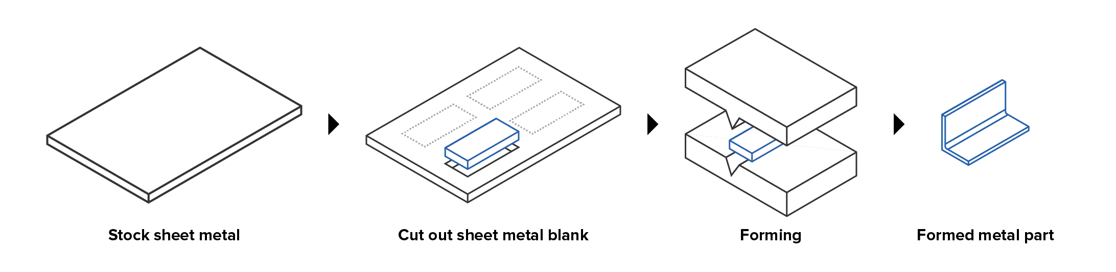
Process workflow for sheet metal forming.
Sheet metal forming is an equipment-intensive operation, and requires machinery and specialized tools that are part-dependent. As shown above, the tool—also referred to as the form or die—is the part of the forming machine acting to bend the sheet. Typically, manufacturers produce their forming tools out of metal by CNC machining in house or outsourcing to service providers. This upfront tooling is expensive and generates significant lead times.
Driven by innovation, industries using metal components are in need of more and more intricate parts with increasing agility in fabrication means. Reconsidering tooling techniques can be a powerful lever for this.
3D Printed Tools for Prototyping and Low Volume Production
Although large size parts such as car body panels are associated with heavy tooling, most metal workshops also produce all kinds of small elements requiring lower bending forces. Replacing those metal tools by 3D printed plastic parts printed in-house for prototyping and low volume production can shorten development times and drive down production costs. In-house printing gives the possibility for engineers to prototype metal parts and iterate tool designs in a matter of hours, achieving complex geometries, while reducing reliance on outsourced providers. Unlike ten years ago, professional desktop printers are affordable, easy to implement, and can be quickly scaled with the demand.
Manufacturers are already using SLA polymer resins to substitute metal jigs, fixtures, and replacement parts in factories. In processes such as injection molding or thermoforming, using test molds in plastic is an effective practise to validate designs and solve DFM challenges before committing to expensive metal molds. Savings in material costs from metal to plastic are significant.
SLA 3D printing technology presents some interesting properties for sheet metal forming. Characterized by high precision and a smooth surface finish, SLA printers can fabricate tools with excellent registration features for better repeatability. Thanks to a broad material library with various mechanical properties, the choice of the resin in regards to the use case can optimize the result of the forming. SLA resins are isotropic and fairly stable under load compared to other 3D printing materials. Plastic tooling can also eliminate a polishing step, as plastic dies do not mark the sheet as metal.
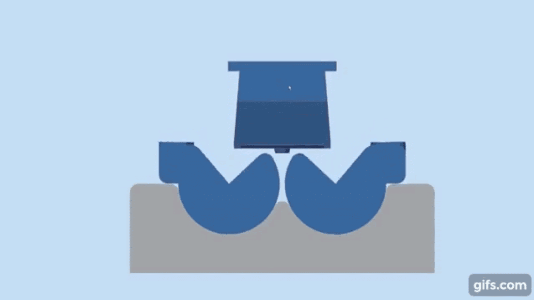
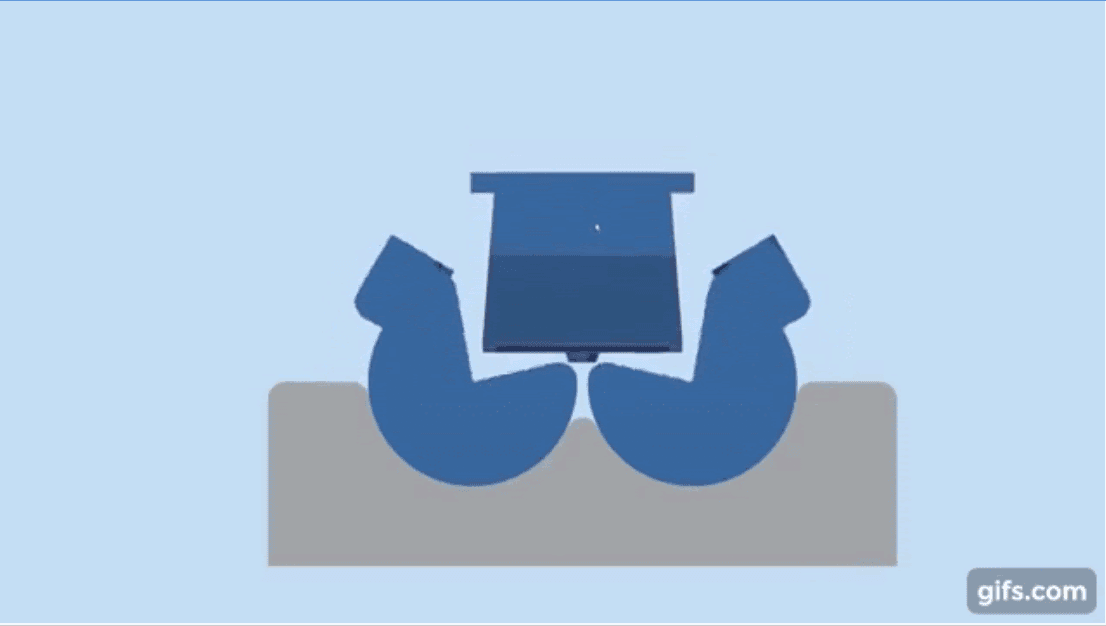
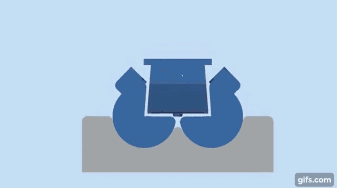
This research work intends to test and demonstrate the viability of SLA 3D printed dies to form sheet metal parts. The mechanism similar to the general sheet metal forming workflow. The difference lies in the design and print of the two-parts tool made of upper and lower dies. The blank sheet is then placed between both plastic dies, and pressed with a hydraulic press or other forming equipment.
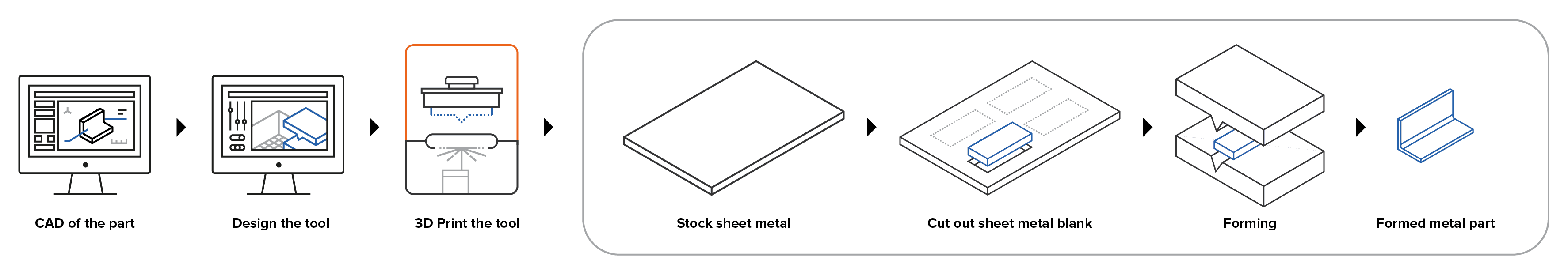
Process workflow for sheet metal forming with 3D printed dies.
Book a Consultation
Get in touch with our 3D printing experts for a 1:1 consultation to find the right solution for your business, receive ROI analyses, test prints, and more.
Experimental Case Study: Sheet Metal Forming With 3D Printed Dies
In this section, we will give recommendations on how to design and use a tool for sheet metal forming and outline the different steps of the method. We will be looking at how to 3D print tools to create a replacement blade guard for an electric saw.
Material and Equipment
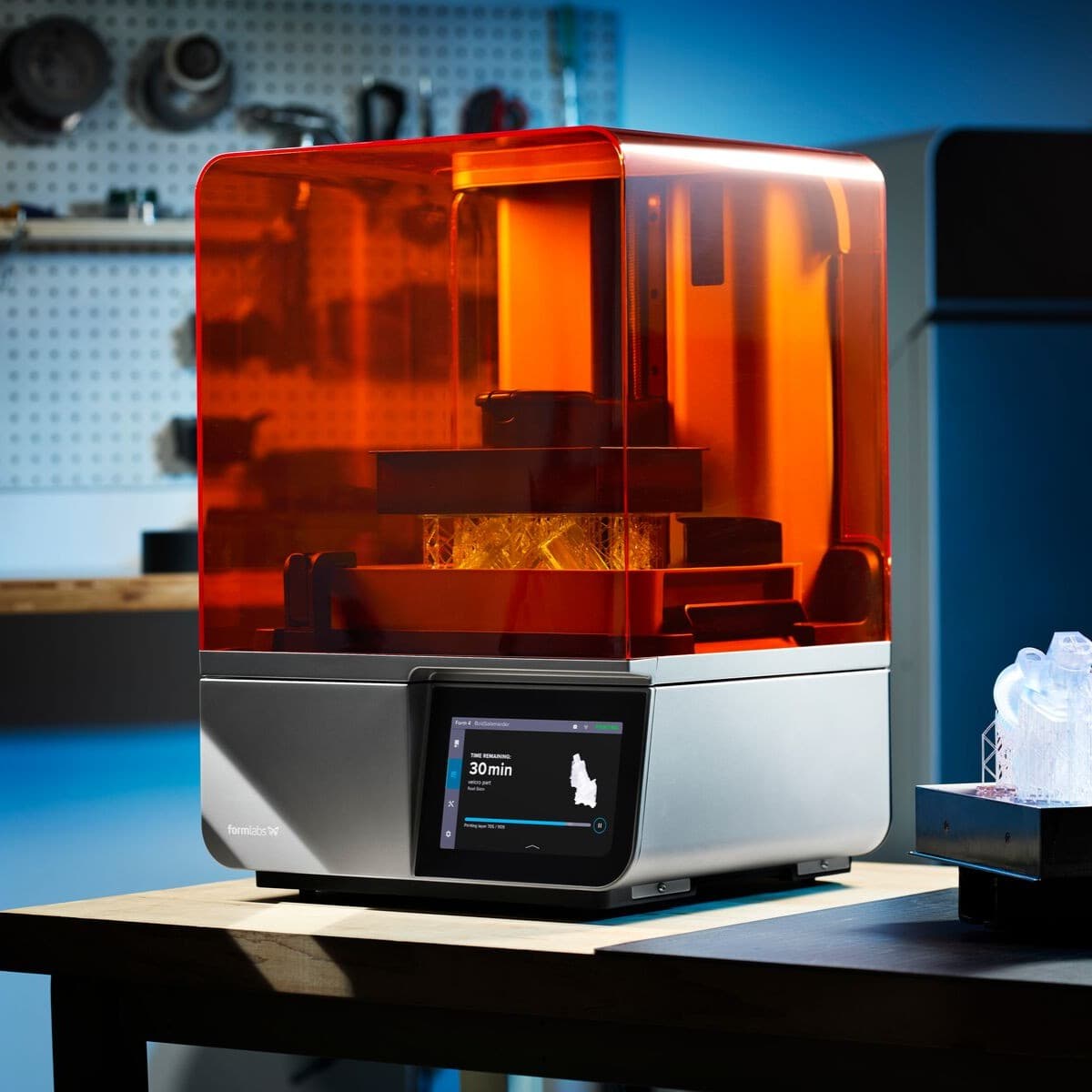
- Formlabs SLA 3D printer with Rigid Resin (other Formlabs Resins can also be used)
- 18-22 gauge steel
- CNC Plasma cutter (hand machining or other cutting equipment can also be used)
- 20 ton H frame hydraulic press (lower forces press can also be used)
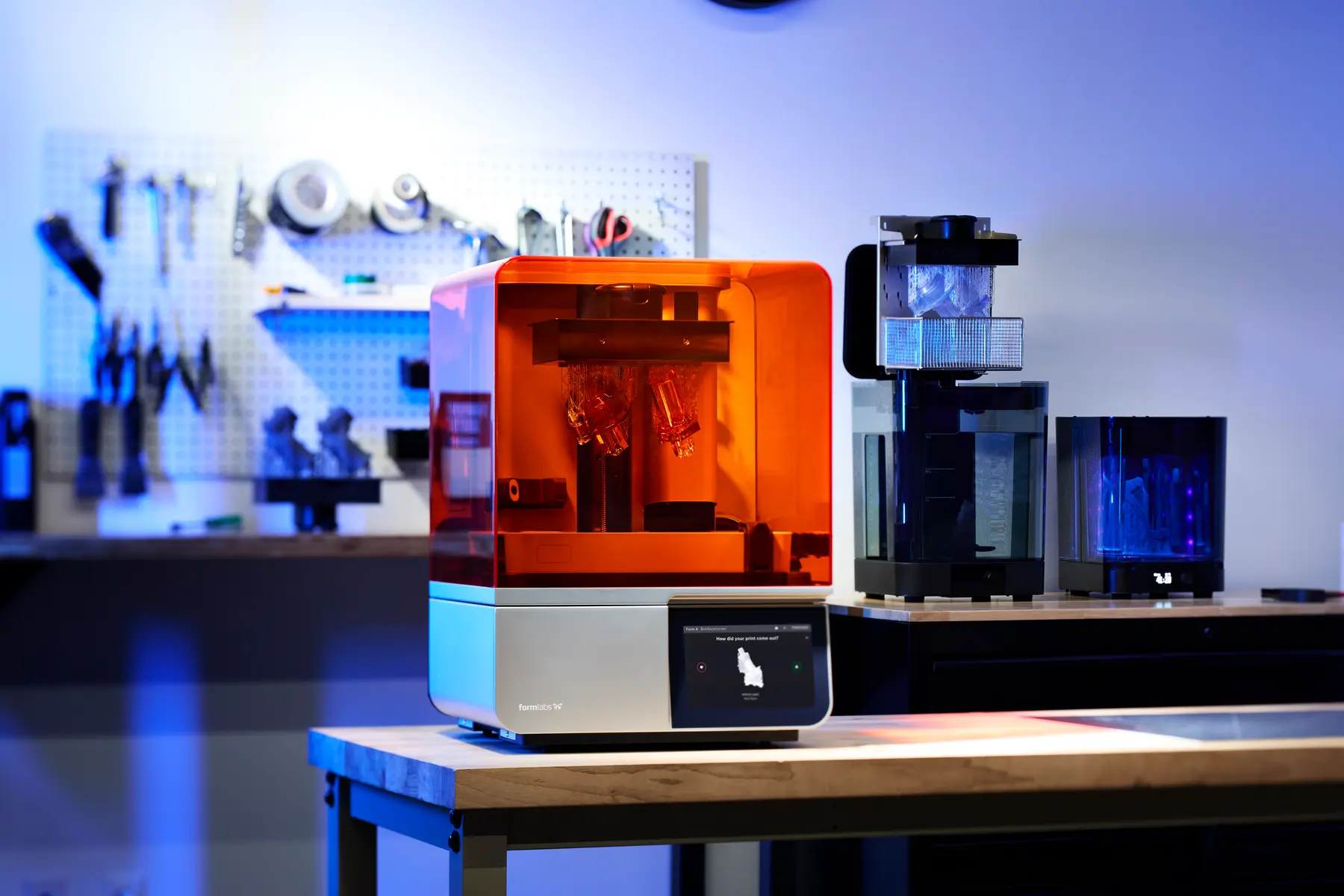
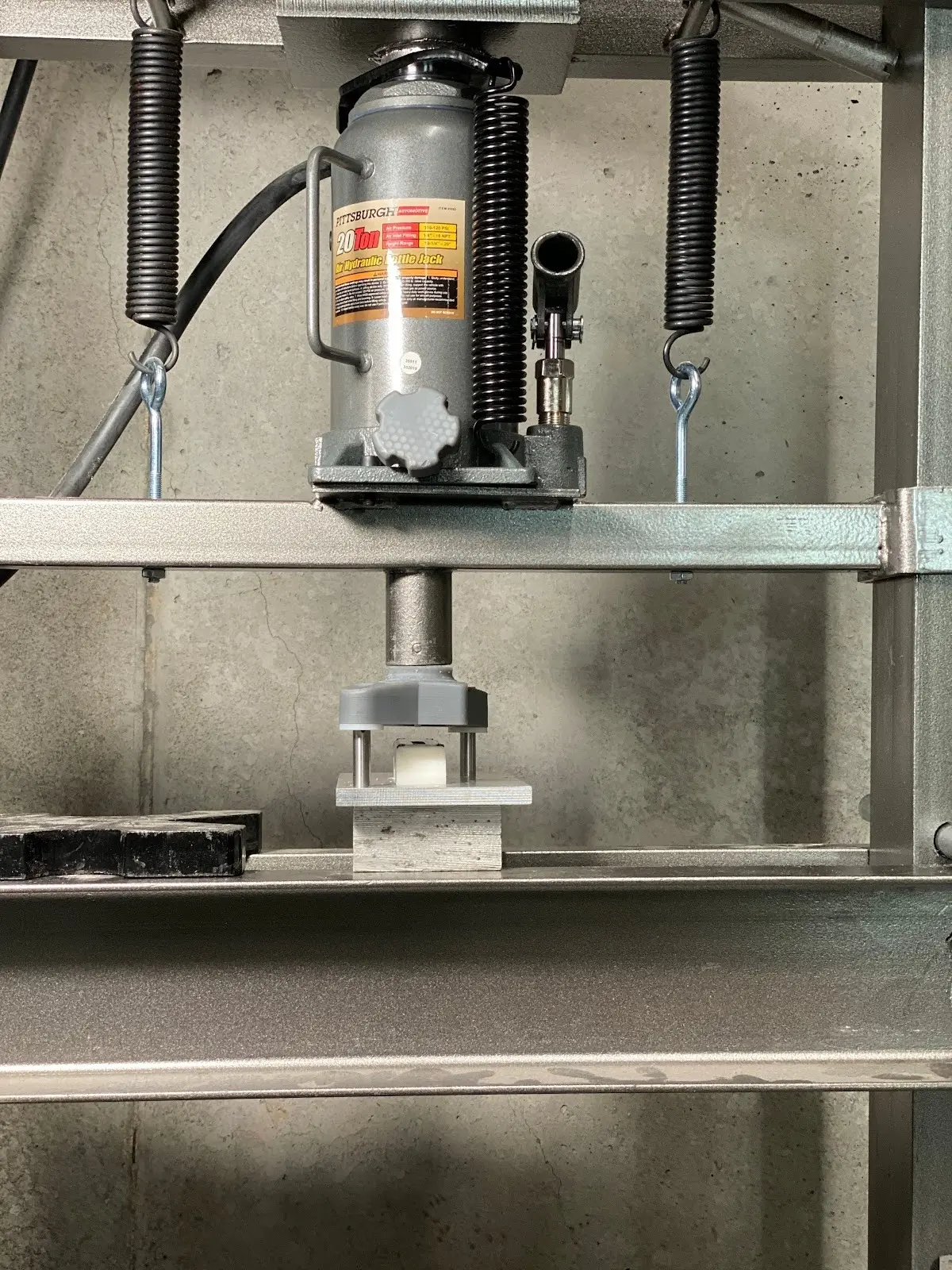
Formlabs SLA printing ecosystem (left) and a hydraulic press (right)
Request a Free Sample Part
See and feel Formlabs quality firsthand. We’ll ship a free 3D printed sample part to your office.
Forming a Replacement Blade Guard
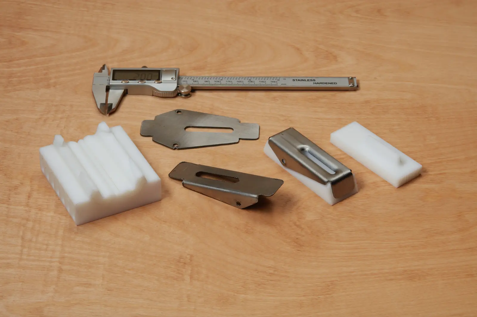
Shane Wighton from the Formlabs engineering team formed a metal part using 3D printed tools for concept validation. The test part was a replacement blade guard for an electric saw. This is an experimental approach to propose a workflow and investigate design concerns.
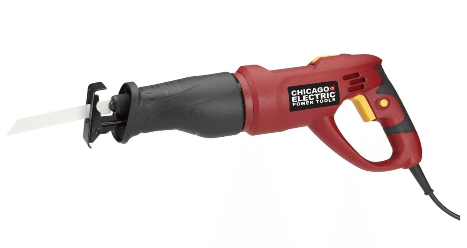
We tested 3D printed tools to create a replacement blade guard for an electric saw. (Source: Chicago Electric)
The geometry of the tool is key to the success of the forming operation. Shane went through a couple of iterations for this experiment, reviewing the CAD files after each test to improve results. Taking advantage of the rapid prototyping with 3D printing, he was able to make six different iterations in a day before choosing a final design. Watch our following webinar to learn more from Shane on design and pressing operations.
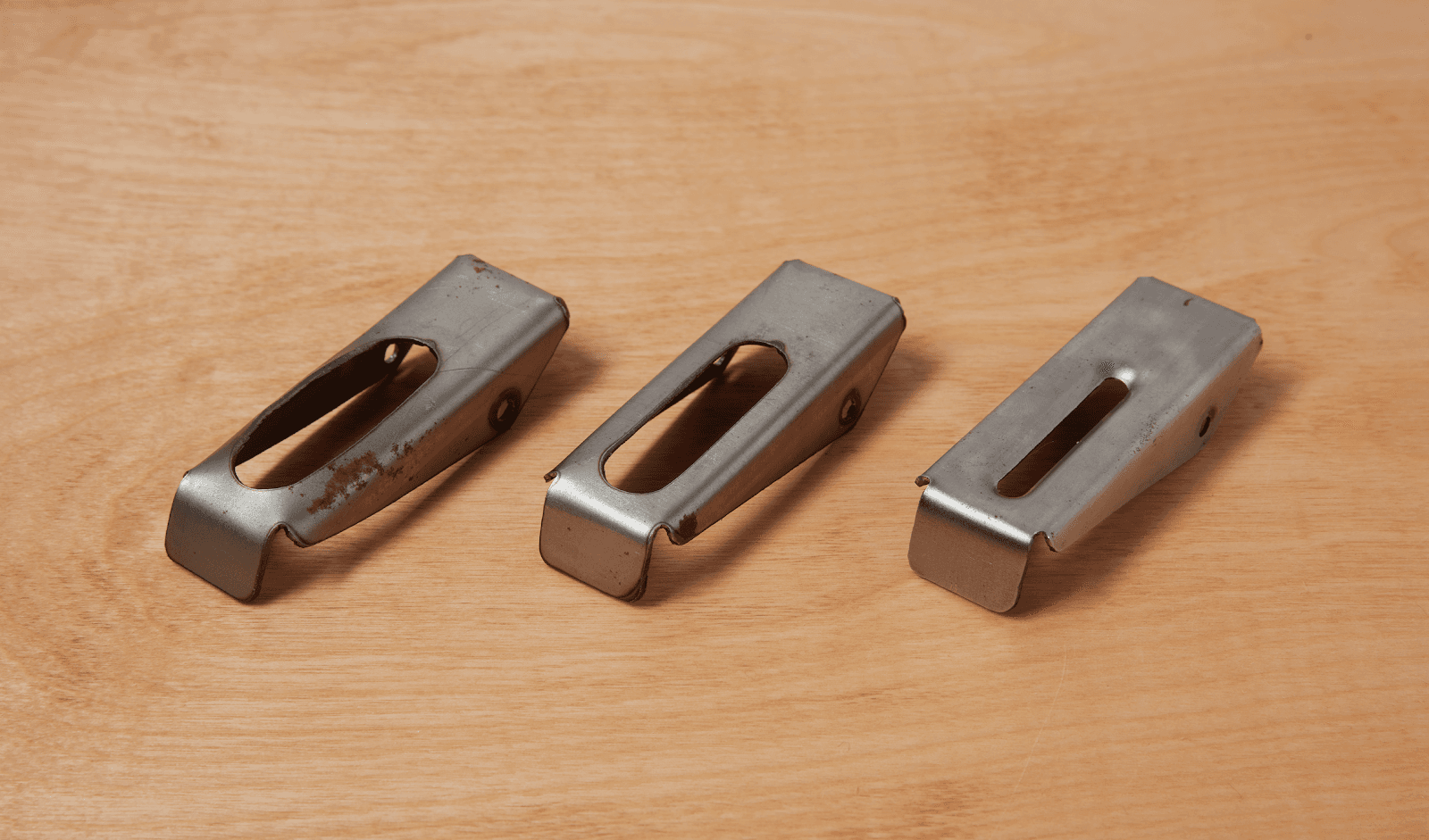
Various iterations of the upper part of the blade guard.
The first thing to do when looking at the CAD of the final part is to determine how to bend it and form it. The upper part of the blade guard presents two complicated features that require a forming treatment. The edge perimeter is bent at 90 degrees very close to a hole, which can lead to distortion of the hole through a bending effort. The hole itself is formed with a radius around the edge, and that kind of inner feature cannot be done with a regular bending machine. The approach is to break the procedure into two forming steps, one for each feature.
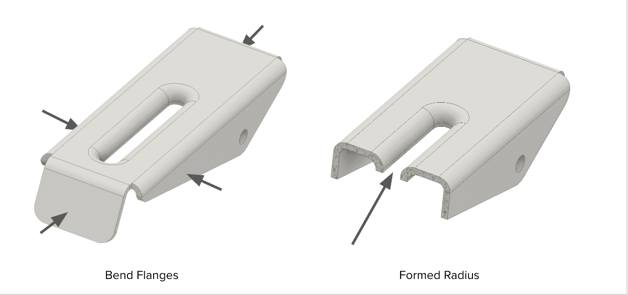
The design of the part shows two distinct features to be formed in two independent steps.
Design Considerations
Here are some important design features to consider when designing the forms.
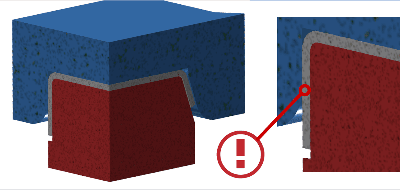
Bending flanges near a hole can provoke distortion.
In sheet metal forming, it is challenging to bend flanges near a hole without altering the hole. Shane’s first trial resulted in damage to the top surface due to the distortion of the hole. To avoid this, make sure that the upper tool is pressing the whole surface of the top part.
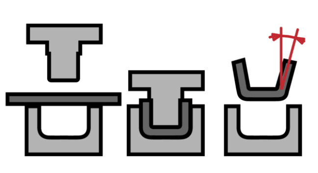
Take metal springiness to bend vertical walls into account.
Metal springiness is a material property characterized by a tendency to return to its original shape. The sheet should be bent beyond 90 degrees to create vertical walls.
Leave clearance in between the two dies.
Remember to leave some space for the metal in between the two parts of the tool or the plastic dies will break. Some CAD software tools have a feature called adaptivity that integrates tolerancing automatically that should be taken into account when designing.
Step-by-Step Method to Form Sheet Metal with 3D Printed Dies
1. Design the Tool
Shane designed the dies and then loaded the files into PreForm, the print preparation software for Formlabs 3D printers. The parts were oriented so critical surfaces were free of support marks. Depending on the geometry, multiple dies can be printed at once on a build platform to increase printing efficiency.
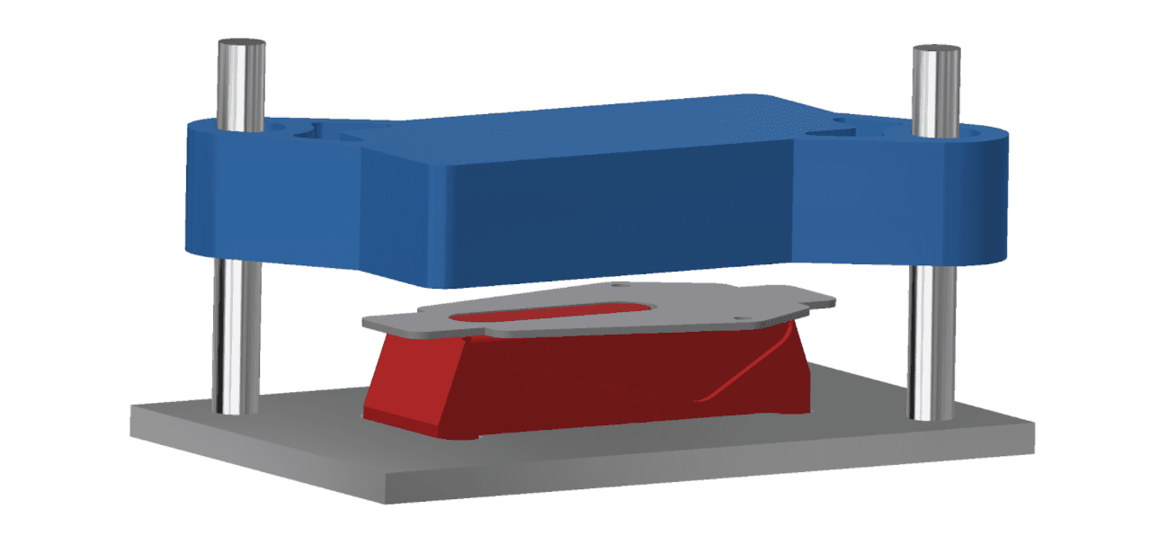
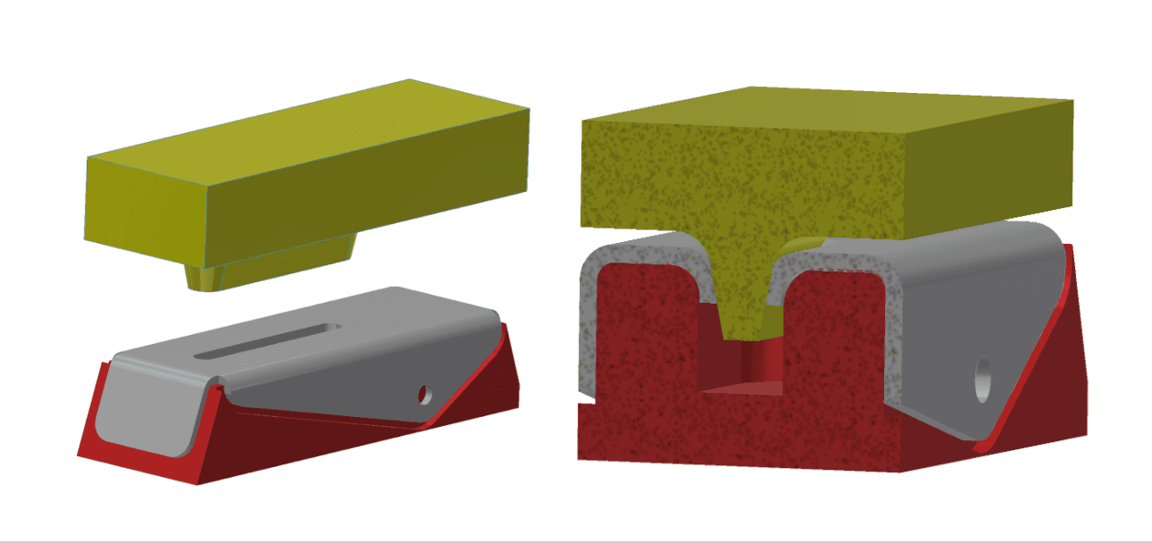
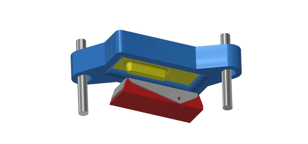
Bending the Flanges
In order to generate the edge bends, the lower form was conceived with a registration feature on top to fit the hole while holding the sheet, and an appropriate radius on the edges to fold the sheet around at the desired angle. The upper die is designed in a U-shape to force the sheet edges around the lower tool when pressed down. If the press is not perfectly accurate, we recommend fabricating a small fixture to guide the tool and align the top and bottom dies. Shane used a lower frame with two precision rods to locate the tools correctly in space. This fixture can be 3D printed or machined, and reused for different dies.
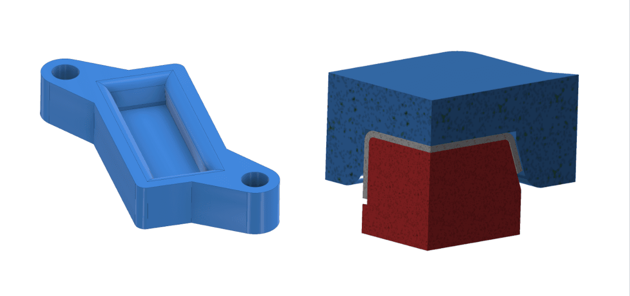
First set of tools: the sheet metal blank seats on the printed lower die and the printed upper die forces the sheet edges around the lower die.
After a couple of iterations, the final design is a rotary action tool which creates a ramp and progressively rolls the material over. The part sits on a form with a clearance pocket and is located by its flanges. One of the advantages of 3D printing compared to machining is that it is easier to fabricate action tools thanks to the freedom in geometry. The smooth surface finish of SLA 3D printing is another benefit as well, especially when using materials such as Rigid Resin.
This final design solves three issues observed during the tests:
-
The ramp action allows bending the flanges beyond 90 degree.
-
Distortion on the top surface is avoided as the action die compresses the sheet.
-
Enough clearance was left in between the two dies to avoid breakage.
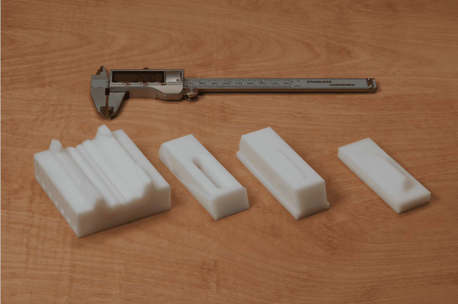
Design of the first set of dies used to bend the flanges.
Forming the Inner Radius
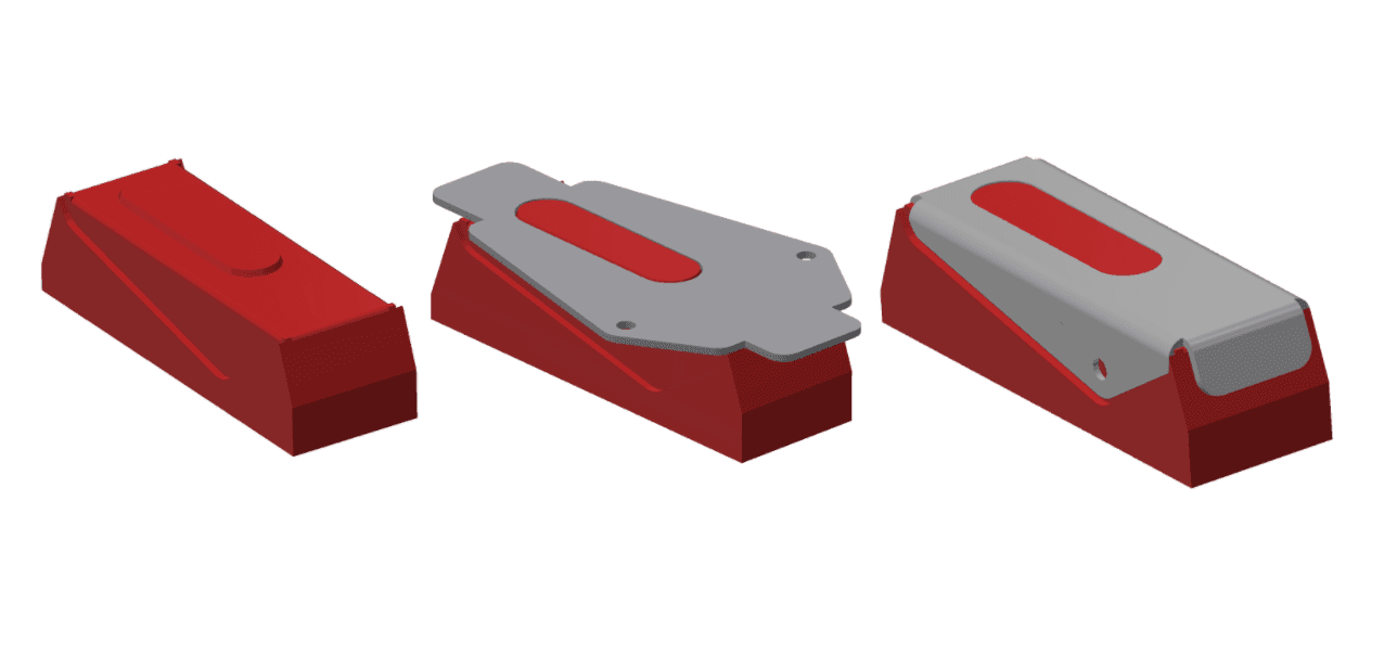
The inner feature is formed in a subsequent step, with a second set of printed tools. The lower die includes an opening at the center where the sheet hole will be pressed into. The part sits on the form with a clearance pocket and is located by its flanges and the tool.
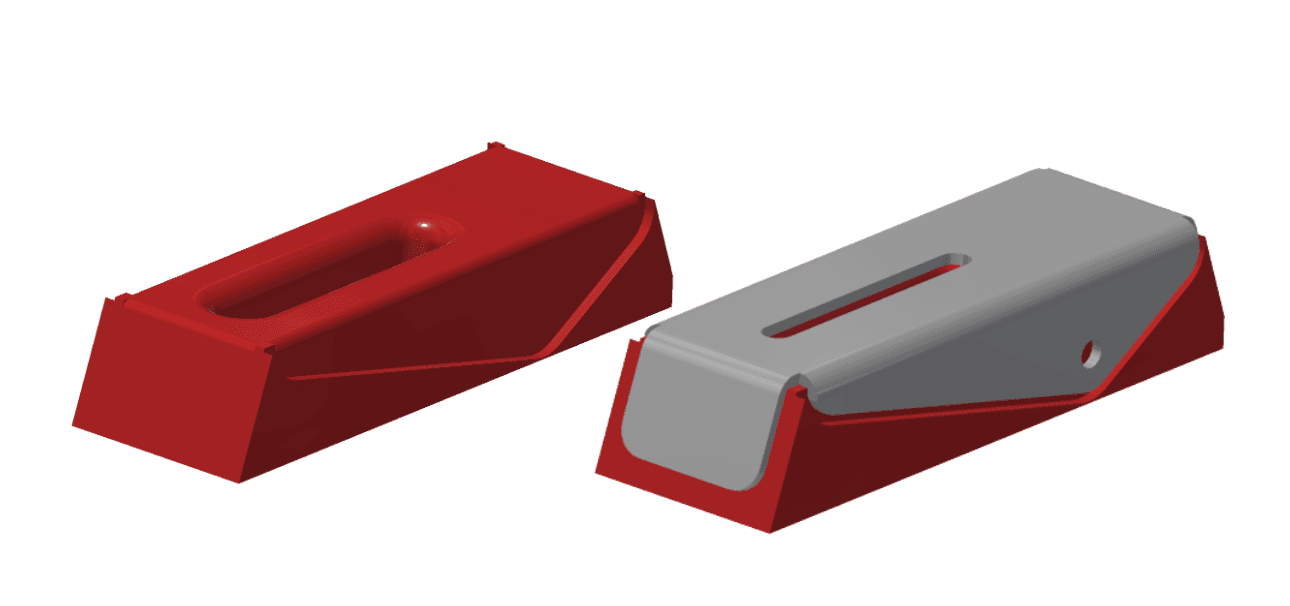
Second set of tool: The upper die is pressing the sheet to form the inner radius.
2. 3D Print the Tool
In just a few hours, the parts shown were printed in Formlabs Rigid Resin on the Form 3 printer at 100 micron layer height. We found that printing with a smaller layer height did not improve operation of the part. The prints were then washed with IPA for 15 minutes twice and post-cured at 80 degrees for 15 minutes.
Dies printed in Rigid Resin.
Formlabs offers a broad library of technical resins with various material properties that can be used to optimize the process for different applications. Shane tested the process with a few of them:
- Rigid Resin was selected for this use case because of its high tensile strength (75 MPa) and tensile modulus, which provides good stiffness that helped the tools withstand high loads without deformation. For hard tools requiring high press forces, Rigid Resin could make the difference between success and failure. However, it would not handle wear for impact loading used for embossed parts because of its lower impact strength. If impact strength is important for your application, see our family of Tough and Durable Resins.
- Tough 2000 Resin, Tough 1500 Resin, and Durable Resin are all great choices when lower forces and dynamic loading are involved. Thanks to their great impact strength, these resins absorb the impact energy without breaking and should withstand wear, hammering, and embossing treatments better than Rigid Resin.
- Fast Model Resin shows a less smooth surface finish but can be a good alternative when in need of a quick print to test the die geometry first.
More information about these resins can be found at here.
3. Cut Out the Sheet Metal Blank Which the Tool Is Designed to Accept
It is common for progressive die forming to cut the material with a punch together with the forming process. However, it is usually not possible to make a punch to cut out the shape using 3D printed dies as the material is not strong enough. Depending on the shape required, different cutting approaches can be used before forming such as bench shear, hand shear, drilling, water jetting, plasma cutting, or laser cutting. For these tests, Shane used a plasma cutter.
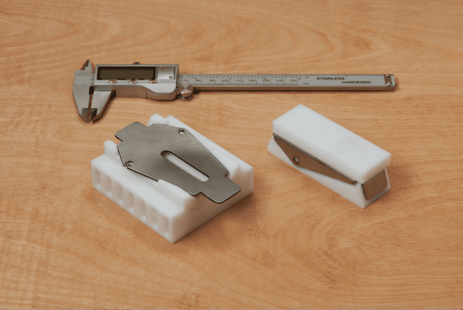
The metal blank on top of the printed dies.
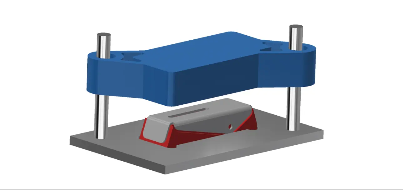
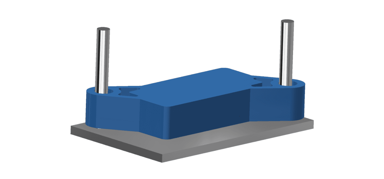
4. Form the Sheet
Subjected to the high forces of the press, the upper die pushes the sheet metal around the matching lower die. We should take into consideration here that the 3D printed dies withstand much higher forces in a forming effort than with a simple bending and the plastic tool presents higher chances to shatter. As SLA parts are isotropic, they are a better choice than parts printed with fused deposition modeling (FDM) 3D printers. We recommend using lubrication to help prevent wear on the tools and reduce the forces required to press. In general, testing with a thinner gauge material is a good practice to validate the tool with less risk of breakage. In this case study only one pressing operation was made per die, but we could potentially go up to hundreds of parts before seeing significant degradation or the tools.
The pressing operation can be observed in this video.
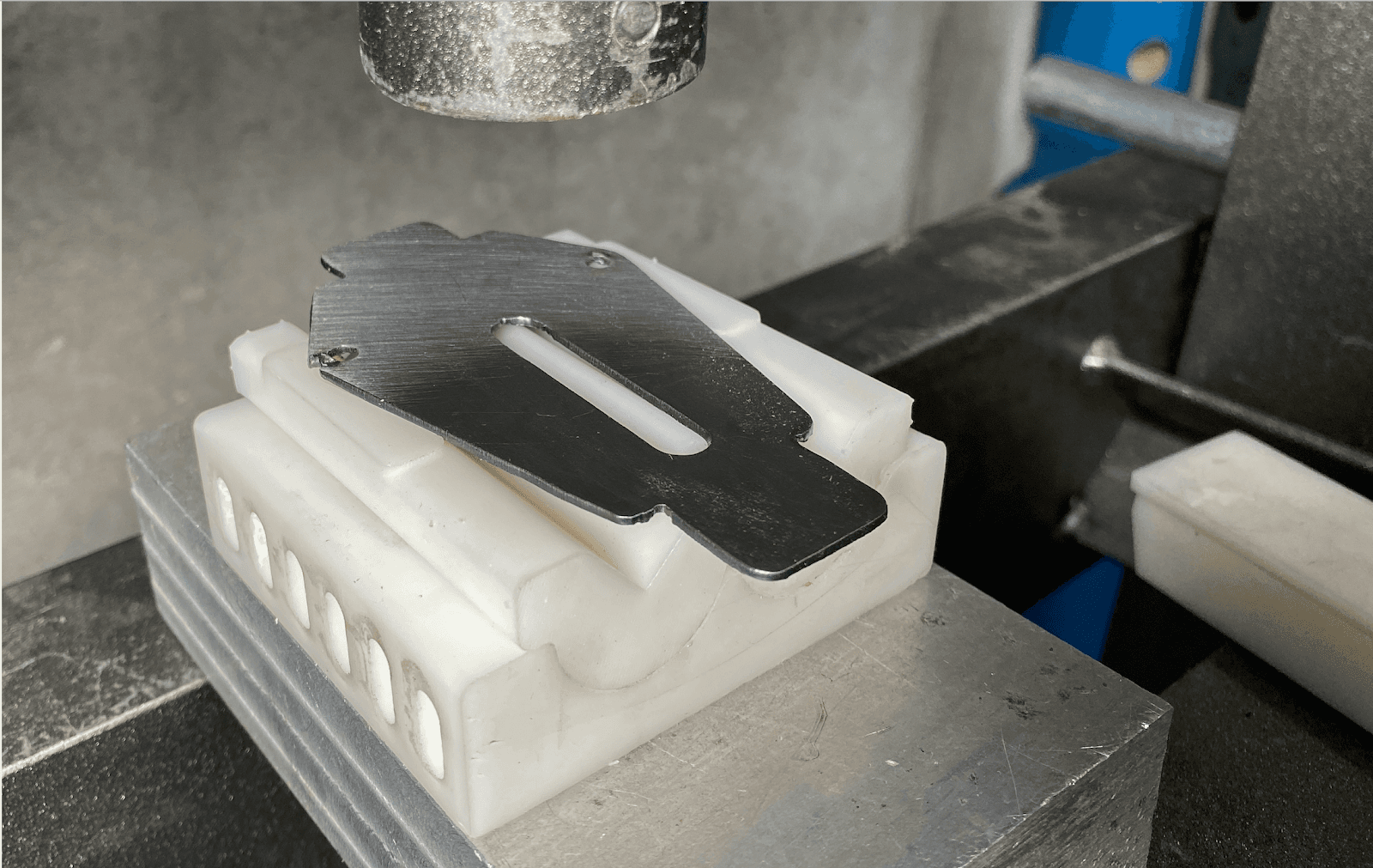
The pressing operation for bending the flanges.
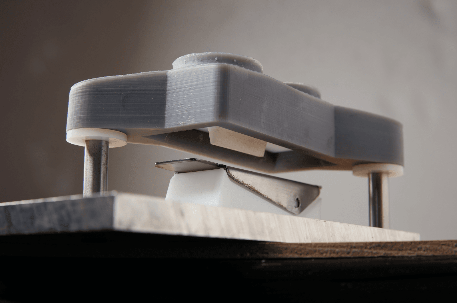
The pressing operation for forming the inner feature.
Cost and Lead Time Comparison
|
Process |
Equipment Needed |
Lead Time |
Material Cost for One Final Part |
Material Cost for 50 Final Parts |
|
In-house 3D printed tool |
Form 3, pressing machine, metal cutting equipment |
10-24 hours (tool print time and post-processing) |
$40 ($30 die + $10 sheet metal stock) |
$60 ($30 die + $30 sheet metal stock) |
|
Outsourced 3D printed tool |
Pressing machine, metal cutting equipment |
Six business days |
$160 ($150 die + $10 sheet metal stock) |
$180 ($150 die + $30 sheet metal stock) |
|
Outsourced metal tool |
Pressing machine, metal cutting equipment |
25 business days |
$460 ($450 die + $10 sheet metal stock) |
$480 ($450 die + $30 sheet metal stock) |
|
Outsourced metal part |
None - fully outsourced |
15 business days |
$230 |
$700 |
3D printing the tool in-house can give flexibility to designers and engineers by reducing the lead time from weeks to a day. For large volume production, prototyping the tool in plastic allows users to verify the design before committing to an expensive metal tool. For short-run production, printed dies would save hundreds of dollars compared to outsourcing the part.
Conclusion
Rethinking toolmaking is a powerful way for reducing costs in metal manufacturing. Beyond the agility provided by prototyping expensive tools, 3D printed plastic dies can be efficient and affordable substitutes to expensive metal tools. For sheet metal forming, 3D printed tools offer multiple opportunities for applications from bent brackets to embossed parts, louvers, grille, and off the shelf set of dies for a press brake.
In our case study, we demonstrated how one of our engineers successfully fabricated a metallic blade guard with the help of 3D printed plastic dies. We could potentially produce dozens of these parts with a single set of dies, bringing short-run production in house.
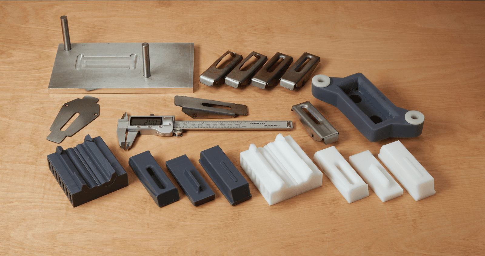
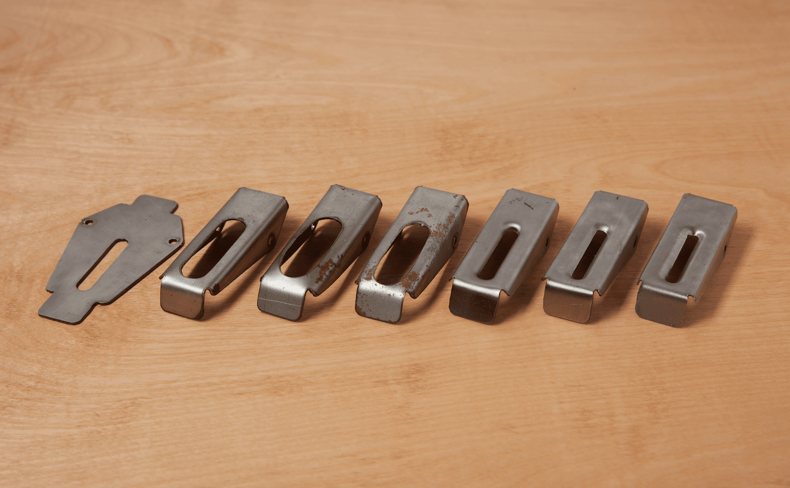
Printed dies and metal parts iterations for forming the blade guard.
Do you have questions about using an SLA printer for sheet metal forming or other engineering and manufacturing applications? Reach out to our solutions specialists for a free information session to answer your questions.
Interested in Learning More?
Do you have questions about using an SLA printer for sheet metal forming or other engineering and manufacturing applications? Reach out to our solutions specialists for a free information session to answer your questions.
Explore our materials to discover one that fits your needs. Curious to see and feel the Formlabs quality firsthand? We’ll ship a free sample part to your office.