
Industrial Investment Casting With 3D Printed Patterns Using Formlabs Clear Cast Resin
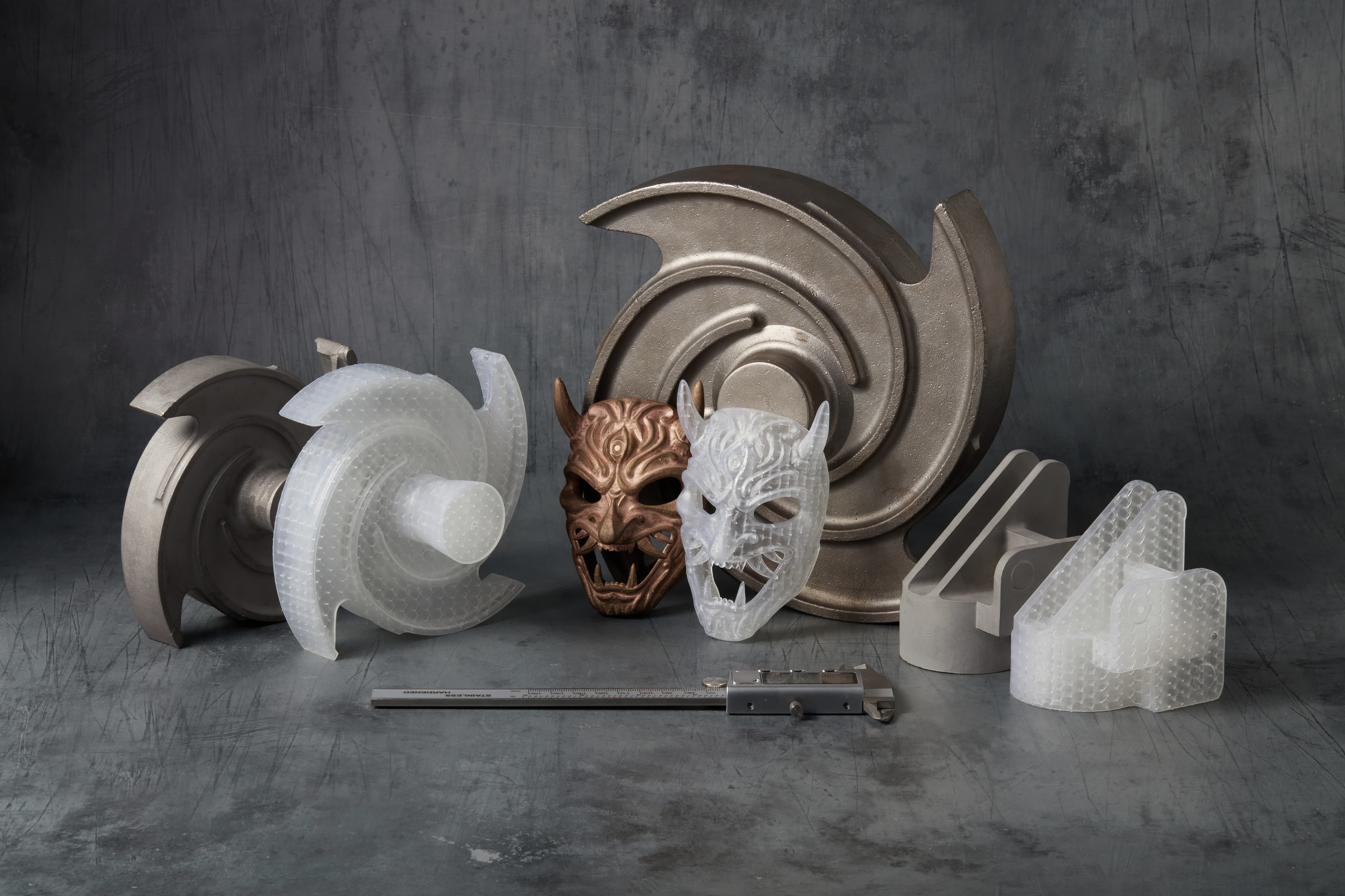
This white paper presents the methods by which several established foundries were able to cast metal parts using 3D printed patterns produced by Formlabs’ stereolithography (SLA) 3D printers. It showcases the full process, detailing the use of latticed Clear Cast Resin acrylic-like parts to produce patterns that were easily integrated into typical industrial investment casting foundry processes without significant workflow or hardware changes. The included case studies also summarize their findings and show how using these patterns enabled the elimination of expensive and high lead time metal tooling that is normally required for the production of parts.
Industrial Investment Casting With 3D Printed Patterns Using Formlabs Clear Cast Resin
This white paper presents the methods by which several established foundries were able to cast metal parts using 3D printed patterns produced by Formlabs’ stereolithography (SLA) 3D printers. It showcases the full process, detailing the use of latticed Clear Cast Resin acrylic-like parts to produce patterns that were easily integrated into typical industrial investment casting foundry processes without significant workflow or hardware changes. The included case studies also summarize their findings and show how using these patterns enabled the elimination of expensive and high lead time metal tooling that is normally required for the production of parts.
Introduction
Investment Casting
Investment casting, also known as lost-wax casting, is a versatile foundry process for producing metal parts with intricate shapes. From lightweight automotive components to golf clubs to jet turbines to art sculptures, this process spans nearly all industries and is relied upon for high-quality and high-integrity metal parts. It enables the production of geometries that cannot be manufactured in any other ways and with a high surface finish.
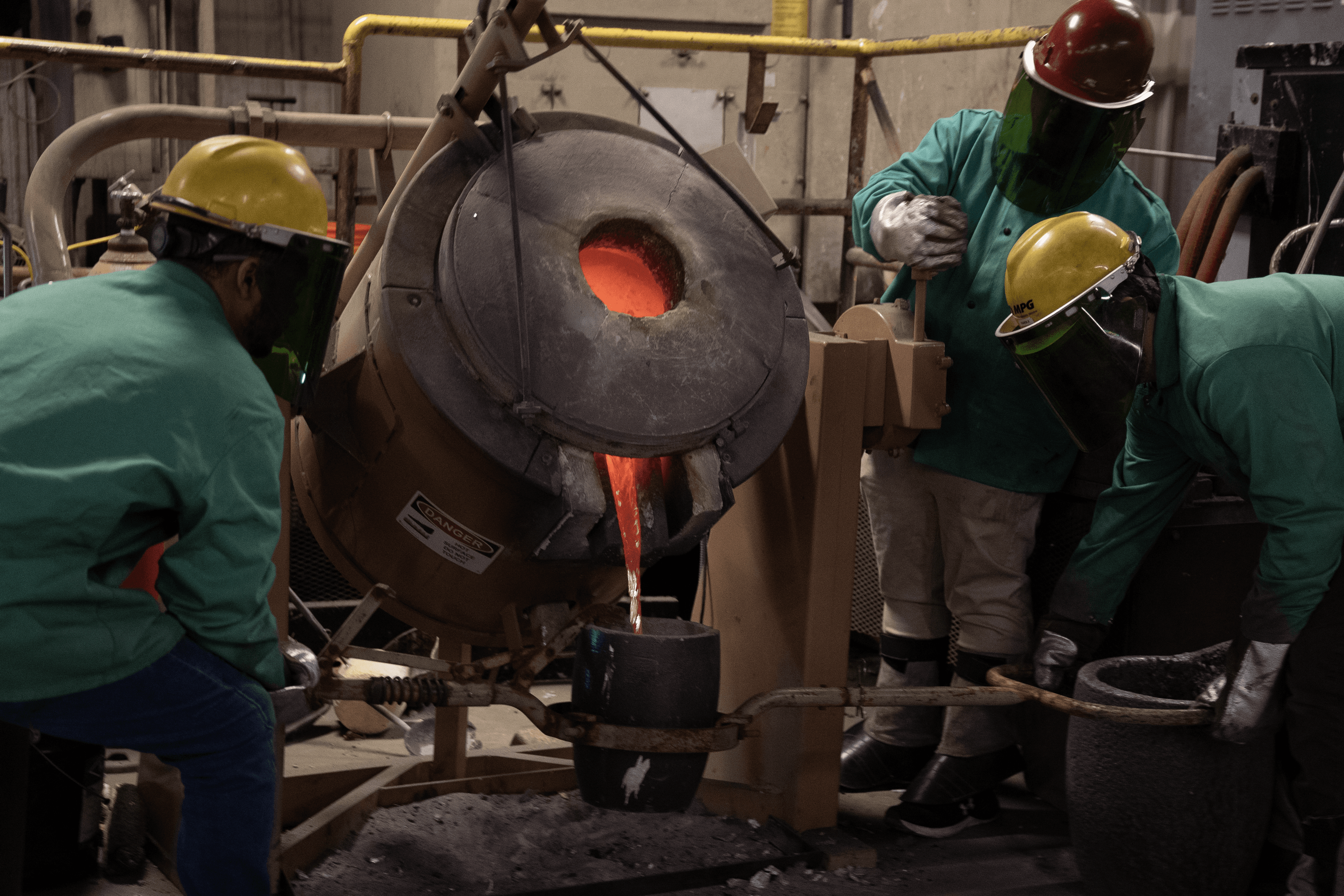
University of Northern Iowa (UNI) team pouring metal from melt furnace into a crucible
Investment casting typically involves three main steps: creating an expendable pattern, making a non-permanent ceramic mold from this pattern, and casting or pouring liquid metal inside the ceramic mold. The pattern is traditionally fabricated through wax injection molding using metal tooling. This technique requires multiple operations, specialized equipment, and extensive labor by skilled workers. Metal tooling is usually achieved by CNC machining and comes with high costs and long lead times. As a result, investment casting can be expensive, especially for low-volume production.
Reducing Lead Time and Cost With 3D Printed Patterns
3D printing the sacrificial pattern has emerged as a cost and time-effective alternative to wax mold creation, enabling faster turnaround times and competitive prices. Because it eliminates tooling, SLA 3D printing allows patterns to be in hand the next day. It requires very limited equipment, freeing up CNC capacity and skilled operators’ time for other high-value tasks. Rapid tooling with 3D printing is already used in common manufacturing processes to iterate quickly, accelerate product development, and bring better products to market. Manufacturers are also 3D printing short-run molds with polymeric 3D printing for low-volume wax and plastic injection molding.
Stereolithography (SLA) 3D printing technology is a great choice for mold and pattern making. It is characterized by a smooth surface finish and high precision that the tool will transfer to the final part, producing surface finishes similar to the wax it replaces. SLA 3D printing also offers unmatched design freedom to create complex and intricate patterns. The Formlabs SLA ecosystem and Clear Cast Resin provide an accessible and reliable solution for pattern making. Form 4L enables large-scale printing with a 35.3 x 19.6 x 35 cm build volume, while Form 4's 20 x 12.5 x 21 cm build volume offers an excellent solution to produce smaller parts at high speed. Formlabs SLA 3D printers can integrate seamlessly into any workflow as they are easy to implement, operate, and maintain.
Clear Cast Resin is an antimony-free material with low ash content (<0.02%), manufactured in the US, and has shown the ability to achieve dimensional accuracy, surface quality, and cost-per-part requirements for a wide range of applications.
To validate this workflow, Formlabs worked with the Foundry 4.0 Center of the University of Northern Iowa (UNI), as well as several foundries, including industrial foundries, service bureaus, and art foundries. The first section of this report goes through the step-by-step method, and then it gives the results of the tests shared by these industrial foundries, including technical data and cost analysis.
Foundries Test Results
Working with these foundries, Bronze, Brass, Aluminum (A356), 6-4 Titanium, 4140 Steel, 8620 Steel, stainless steel 316, and 17-4 PH were all cast. The parts were burnt out in a furnace between 700 °C and 900 °C in all cases, with no autoclave. Most parts were connected to standard investment casting wax sprues and dipped in each customer’s particular shelling system.
Case Study
While there are many different exact chemistries and methods used in investment casting and tested with Formlabs’ process, this is how the Foundry 4.0 at the University of Northern Iowa successfully was able to cast parts in Aluminum A356.
Parts were initially made into a tetrahedron lattice using Materialise’s Lattice Module with 0.5 mm walls and 1 mm diameter lattice diameter. This was then printed at 100 micron layer heights with the Form 3L and cleaned following Formlabs’ standard printing process. Once post-processed, the parts were adhered to a stock casting sprue using sticky wax. They then used a 100% silica shelling system, starting with Remet RP-1 flour as a primary coat, and RG-1 for backing coats, typically using 2 primary coat dips and 3 backing coats, with stucco applied after the second primary coat and after each subsequent dip. All of the shelling process was carried out automatically by an automation process to guarantee the most uniform possible coat with a minimal amount of manual labor, taking in total 9-10 hours for a single sprue.
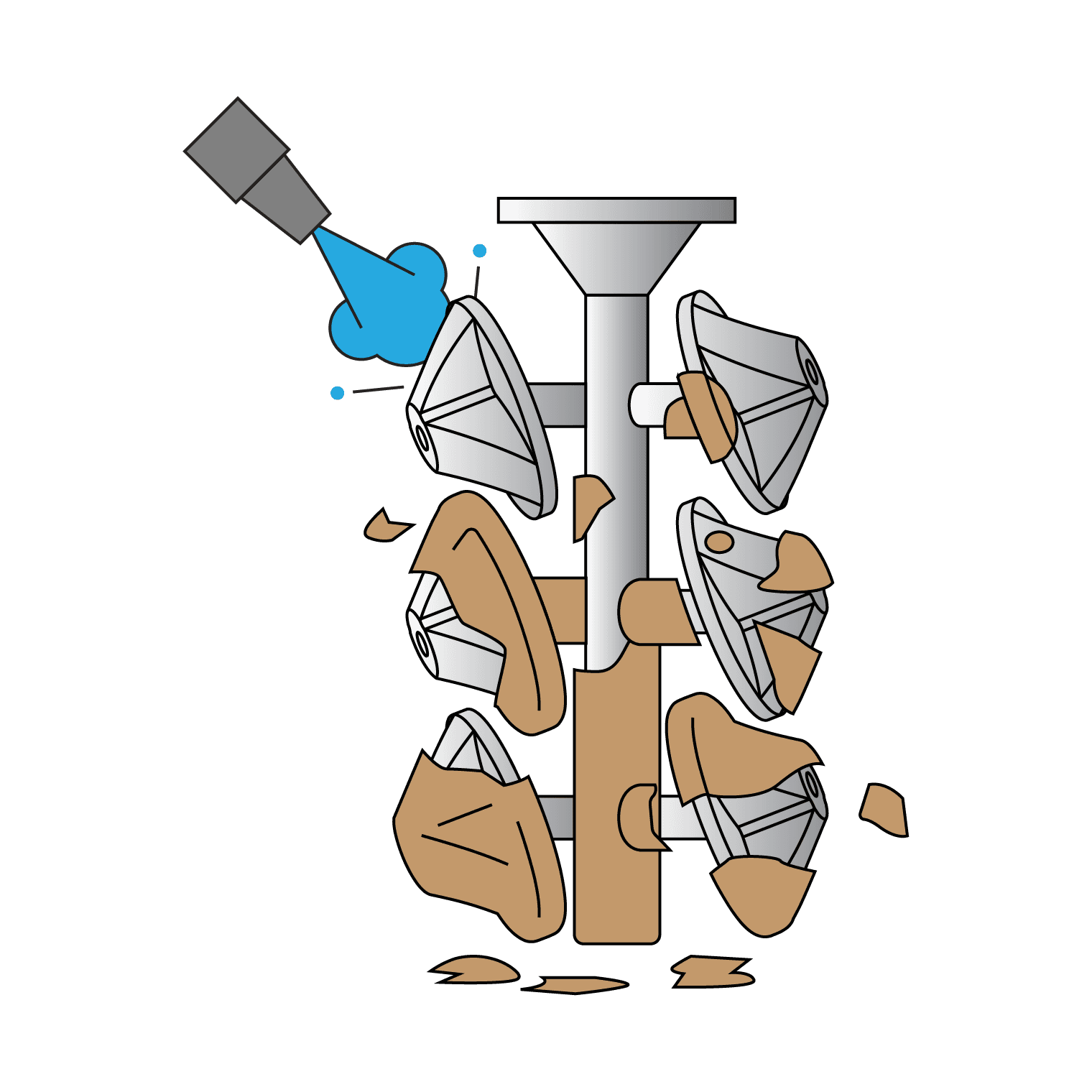
Once dried, the part was flash-fired at 900 °C (1650 °F) for 2 hrs, and then cooled and transferred to the casting facility. Prior to casting, the shell was preheated to 540 °C and then the aluminum was cast when it was 700 °C-750 °C. They then removed the shells via a combination of breaking off the bulk pieces and blasting off the remainder, resulting in a clean final piece.
Foundry Feedback
“Our main reason for purchasing the 3L was pattern cost. For this impeller, we started out using our customers traditional wax injection tooling that was difficult and time consuming to run. We went to a PMMA printed pattern to save on labor, but the pattern costs kept rising to over $300 the last time we used one. Even amortizing the 3L and associated equipment, we will at a minimum break even on costs for our current order, and save over $200 per part on upcoming orders. There is very little difference in our process, both before and after casting, between the PMMA and Clear Cast SLA patterns.”
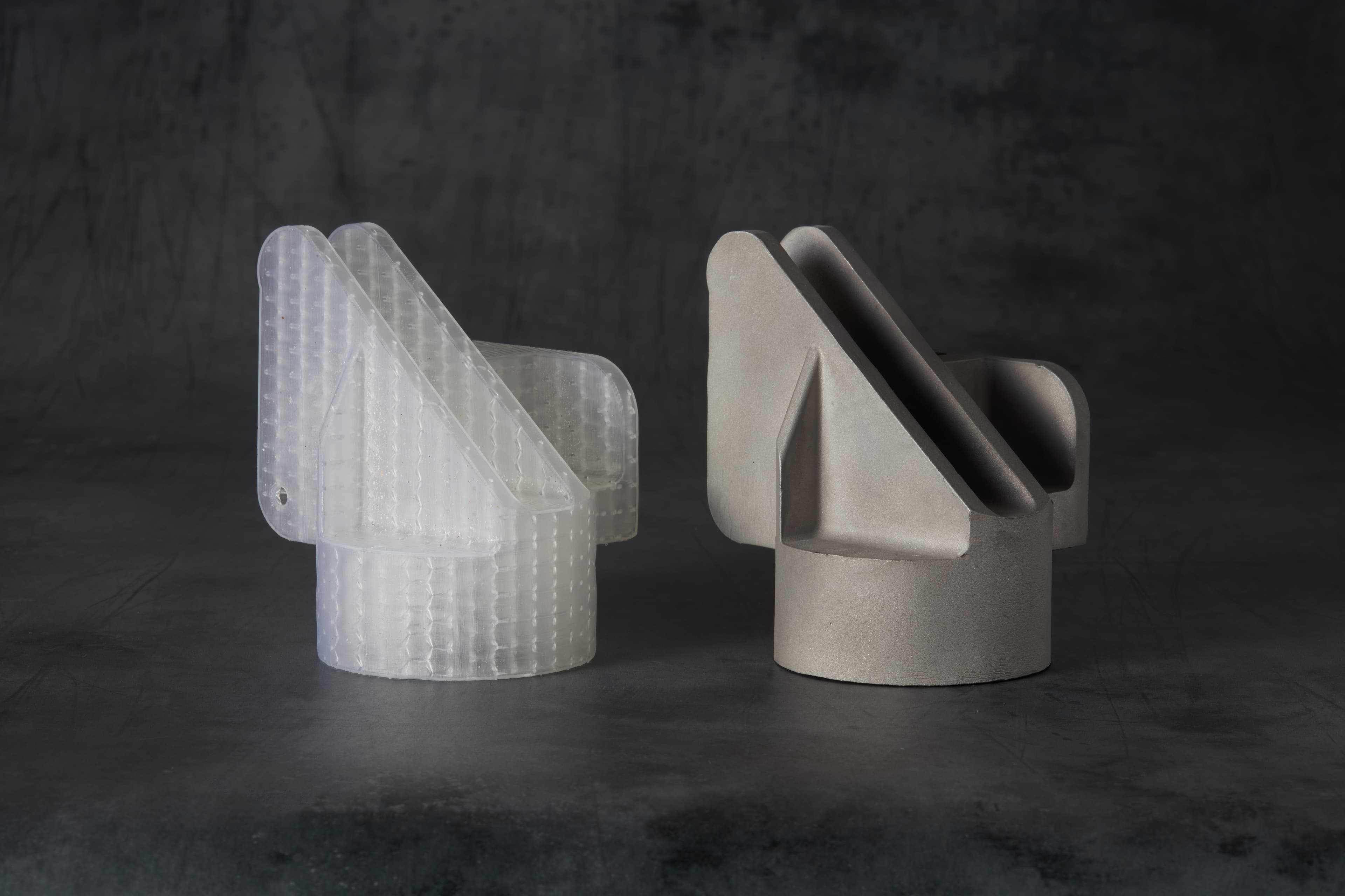
Titanium Impeller alongside its Clear Cast Pattern.
“The Formlabs system, utilizing the Clear Cast Resin, allows us to produce highly detailed patterns for art casting faster, more consistently, and with a fraction of the labor costs required of traditional hand chased wax patterns. The low cost of acquiring additional machines provides us with a quick path to scale out to meet client demands. We’ve also been very impressed with the rapid rate of innovation, completeness of the Formlabs ecosystem, and the knowledge and support that they have provided us.”
Results and Cost Analysis
Based on user feedback, patterns 3D printed with Formlabs Clear Cast Resin can produce investment cast parts with quality comparable to traditional wax patterns. 3D printed patterns may be more brittle than wax patterns and should be handled with care. However, the burnout is clean without any noticeable ash left in the visible portion of the shell. The final metal part does not show any unusual defects.
By allowing the direct production of patterns, Formlabs allows parts to be produced immediately and without tooling, soluble cores, or other complex wax formation techniques. Features like undercuts, tortuous channels, and thin walls that prove difficult to pattern for wax injection are easy to 3D print. The table below illustrates the cost and time savings of using 3D printed tools compared to alternative methods.
|
PART |
COMPLEX IMPELLER PART |
SIMPLE PUMP IMPELLER - 12” |
|
Volume of production |
50 parts |
50 parts |
|
Alternative tooling method |
Wax Injection with metal tooling, soluble wax cores, and wax chills |
Wax Injection with metal tooling |
|
Alternative tooling cost |
$60,000 |
$11,000 |
|
Cost - Printed |
$78/part |
$30/part |
|
Lead time savings |
14 weeks |
8 weeks |
This table shows that on many parts, even simple ones, foundries can save tens of thousands of dollars.
Process Overview
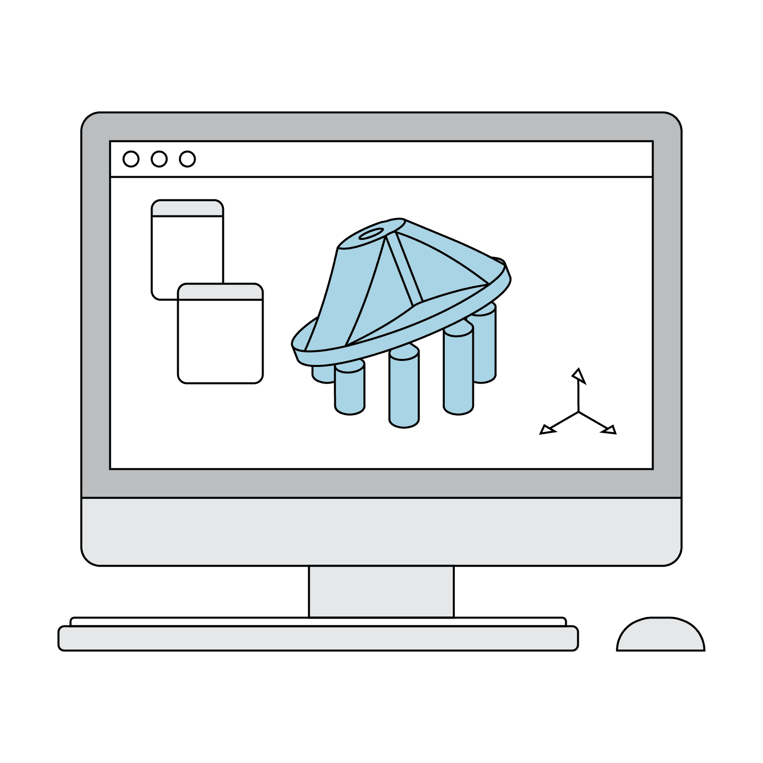
1. Pattern Design
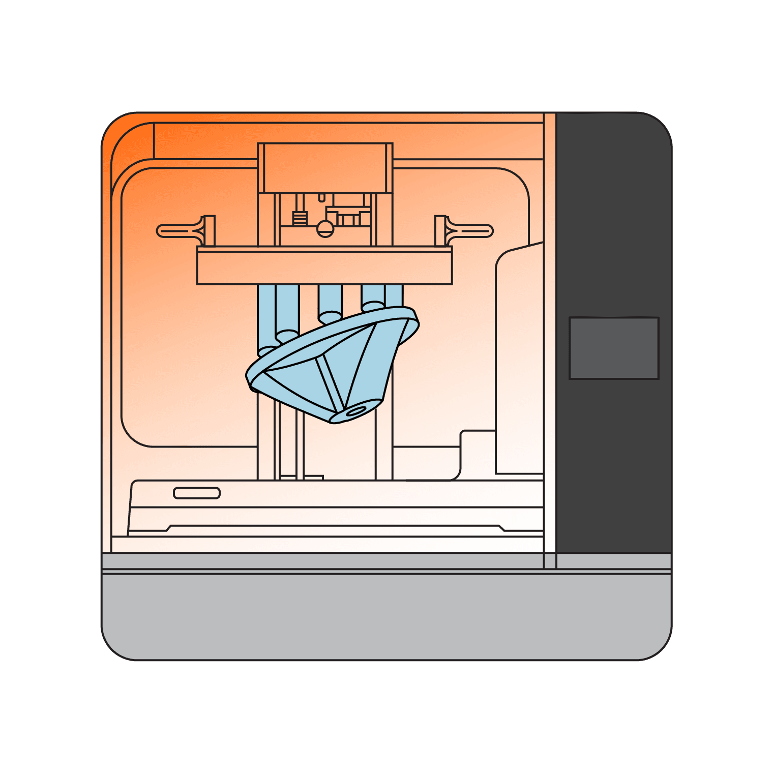
2. Pattern 3D Printing

3. Pattern Preparation
4. Shell Making
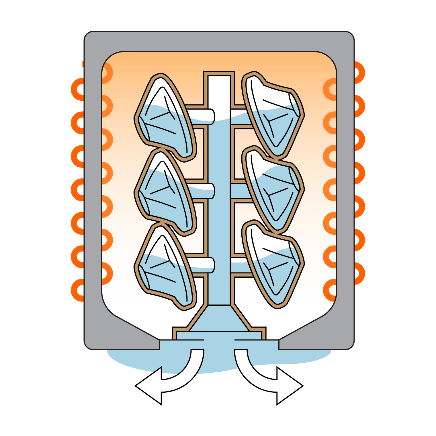
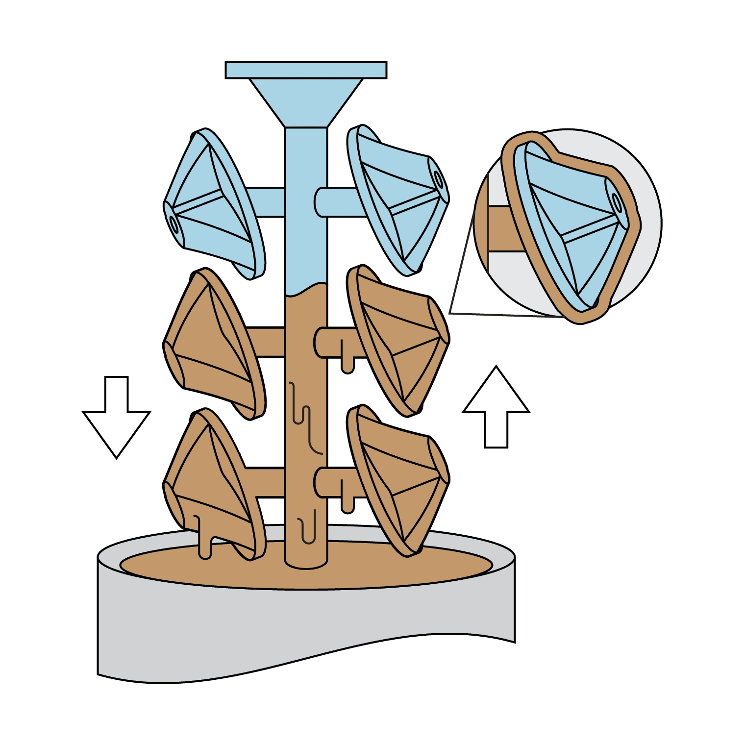
5. Pattern Burnout

6. Metal Pouring
7. Shell Removal
8. Cutting Off and Finishing
Method
The next section is a step-by-step guide to get started with 3D printed patterns for investment casting based on the feedback and guidelines from more than 10 foundries.
Pattern Design
Sacrificial patterns need to be strong enough to withstand the pressure of the ceramic slurry, while also being thin enough to burn away, leaving as little ash behind as possible. To achieve this, parts utilize a special design that features thin outer walls combined with a strong inner lattice scaffolding. Software solutions are available on the market to help hollow the part and build lattice structures. This study was made using Materialise Magics’ Investment Casting Tools.
1. Design the part with the CAD software of your choice.
2. Hollow your part and build the internal lattice structure. Import the CAD file into the lattice module following Materialise instructions and set the design settings. Latticing allows users to easily control the outer shell, the dimensions of the internal structure, and the placement of drain holes. The right choice of settings depends on your application and requirements, the next paragraph explains the influence of these parameters on the process. Follow the table below for reference.
|
Settings |
Dimension (mm) [min/max] |
|
Wall thickness |
0.5 [0.4/1] |
|
Detail size |
0.5 |
|
Leg thickness (a) |
0.75 [0.5/1] |
|
Leg length (b) |
3 |
|
Radius outer circle (r2) |
2 |
|
Radius inner circle(r1) |
2 |
Enter the lattice settings in the Lattice Module in three steps.
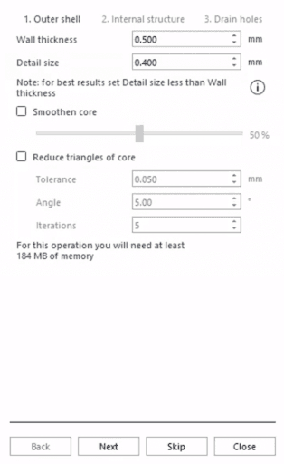
2.1. Set the outer shell. Thinner walls increase cast success but decrease print success and weaken the parts. Formlabs suggests starting with 0.5 mm wall thickness, increasing only in case of print failure or issues with dimensional accuracy. Detail size can remain at the standard value of 0.5 mm and is non-critical to the casting process.
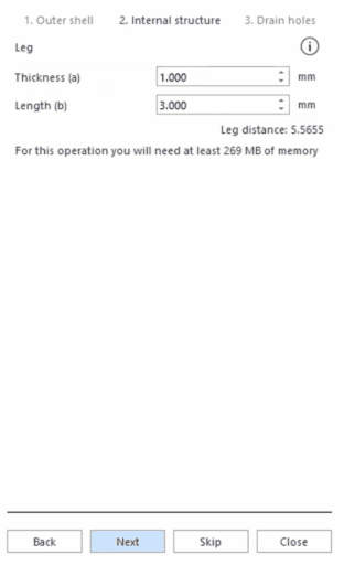
2.2. Set the internal structure. The lattice supports the exterior of the part, prevents warping, and enables printing with thin walls. Increasing the leg thickness, referring to the lattice diameter, reinforces the pattern but increases the chance that the pattern will expand and crack the shell. Formlabs recommends starting with a leg thickness of 0.75 mm. The leg length is the distance between the lattice connections and can remain at the standard value of 3 mm.
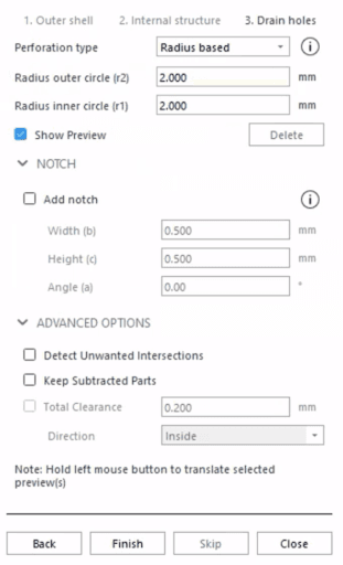
2.3. Add drain and vent holes. These holes serve two purposes: they reduce risks of print failure through “suction cups” or “explosions” and they allow for internally trapped liquid resin to drain out. It is helpful to have a print orientation in mind when adding these holes, following Formlabs’ orientation best practices guide.
- 2.3.1. Place holes at the top and bottom of the part orientation.
- 2.3.2. Place holes on sacrificial surfaces (to be machine or cut, like a gate) to simplify post-processing.
- 2.3.3. Formlabs recommends a minimum of 1 mm radius, and can even be increased as long as it does not alter a critical surface.
- 2.3.4. Create straight holes (r1=r2) or only slightly chamfered holes (r1>r2).
- 2.3.5. Place vent holes in the location where the sprue will be placed to allow for good airflow during burnout.
2.4. Convert your exported files to 3MF to reduce the file size. Latticed parts can result in large file sizes, which slow down the print preparation and support generation process.
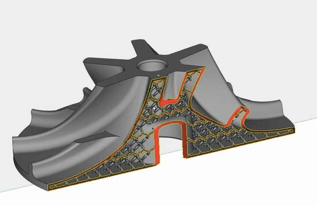
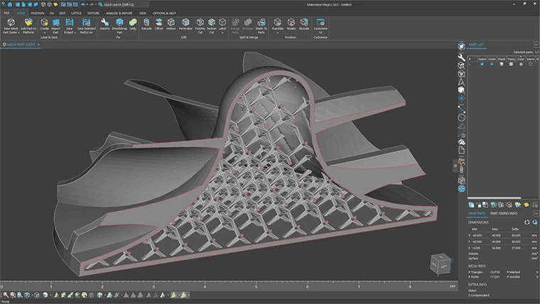
CAD design of UNI’s impeller pattern with lattice structures built in Materialise Magics.
Pattern 3D Printing
3. Prepare the file in Formlabs PreForm software according to the PreForm guide.
3.1. Orient the model 30-45 degrees relative to the build platform. Consider the location of vent holes to promote resin drain and minimize cupping.
3.2. Add a full raft and light supports, using 0.75 density and 0.30 mm touch tips or smaller. They support the model and ensure easy removal after printing, without damaging the thin walls. Avoid support locations on critical surfaces.
4. 3D print on Form 4L, Form 3L, or Form 4 with Clear Cast Resin at 100 micron layer height, following Formlabs’ instructions. Physical characterizations of Formlabs resins are available in the next section. Formlabs recommends using Flex Build Platform or Build Platform 2L for printing parts with large surface areas.
5. Wash the part in Form Wash L in IPA for 10 minutes, blow out the interior with compressed air, and then an additional wash of 5 minutes. Wipe down any additional resin using a paper towel and IPA. Allow the part to air dry for 30 minutes or dry the remaining IPA off of the surface with compressed air. It is critical to remove all trapped IPA, as any remaining liquid can cause vapor in burnout and lead to shell cracking.
6. Post-cure the part in Form Cure L for 15 minutes at 35 °C. Because curing reinforces the stiffness of the part, it is easier to remove the supports before. However, removing the supports after curing can prevent breaking the part, especially for fragile geometries. If the part is prone to warpage, use a post-curing schedule with no heat.
7. Remove and clean the supports. Use standard tools such as scrapers, flat snips, or 100- 300 grit sandpaper.
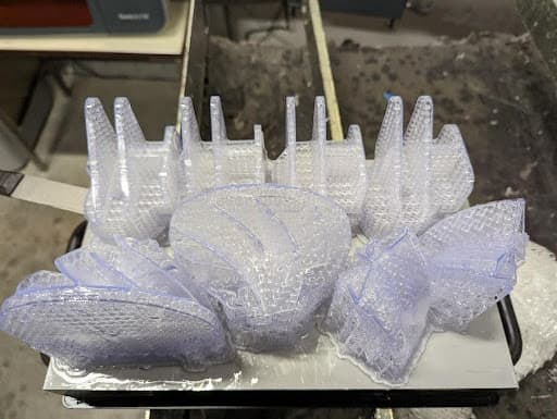
UNi’s patterns on the Form 3L Build Platform after impression (first image), then the supports are removed and sanded (second image).
Pattern Preparation
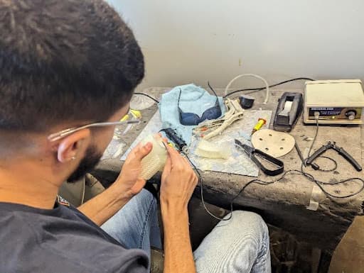
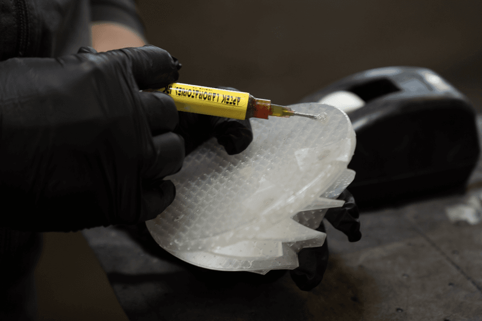
8. Fill the vents and drain holes using a standard foundry wax or a UV resin pen for about 30 seconds to set the resin. These pens such as Aptek Laboratories UVIFILL- SL-TX can easily be ordered on Amazon. Check the fit of the holes by forcing compressed air into the last hole and looking for leaks.
9. Follow your usual process for pattern assembly. Prepare the pattern for gating and treeing, optimizing your gating setup to aid oxygen flow during the burnout process. Common practice is to attach the parts to a wax tree using an adhesive wax and attach a T-bar to the tree for the dipping process. Standard foundry wax is most commonly used but the sprue can be 3D printed as part of the pattern with success.
10. Optional venting: To ensure first-part yield, some foundries attach vents to the pattern to improve airflow in burnout in the same way they add gating. This step does increase success and is recommended when producing extremely short runs of parts, like one-offs or time-sensitive deliveries. Cooling the shell after burnout and patching the hole with investment is required for venting in the assembly process.
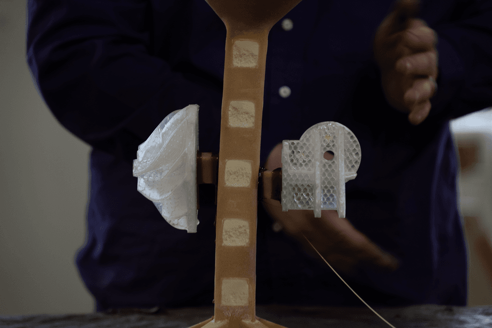
UNI’s team plugs the holes with wax (first image) and attaches the pattern to the tree (second image) for automated investment casting using a pick-and-place robot.
Shell Making
11. Follow your usual process to dip the tree in the slurry. Some foundries alter their slurry to a more “forgiving” mix which expands more or they add dips in an attempt to reduce cracking. Formlabs suggests starting with your standard process and has seen no issue with shell adhesion to printed patterns when the above process is followed. For reference, UNI uses an automated robotic cell performing six dips.
11.1. One dip in a primary slurry without sand to preserve the surface finish.
11.2. One dip in a back-up slurry and primary sand then three dips in the back-up slurry and back-up sand to build the thickness and strength of the shell.
11.3. One dip in the primary slurry without sand as a seal coating.
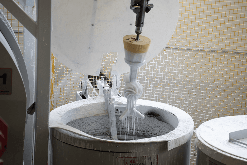
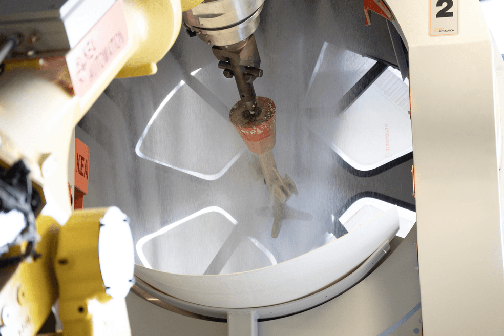
UNI’s robotic cell picks the tree and dips it in the primary slurry (first image), drains excess slurry at the end of the process, then inserts it into a rainfall sander (second image).
Pattern Burnout
12. Follow your usual process to burn out the pattern in a furnace. Flash fire is a standard method to employ, it heats the pattern between 705 °C and 900 °C (1,300 °F and 1,650 °F) for two hours. A foundry must have access to a high-temperature furnace and the ability to encourage sufficient oxygen flow. In an autoclave or with temperatures below to 650 °C (1200 °F), patterns are likely to crack the shell.
13. Check for any cracking or flashing in the shell after the burnout and blow out any remaining ash from the mold. Burnout of a printed pattern will result in some small degree of ash. Clear Cast Resin is antimony-free, contains under 0.020% ash by mass, and is printed hollow, so only a trivial amount of ash may be left behind.
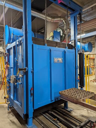
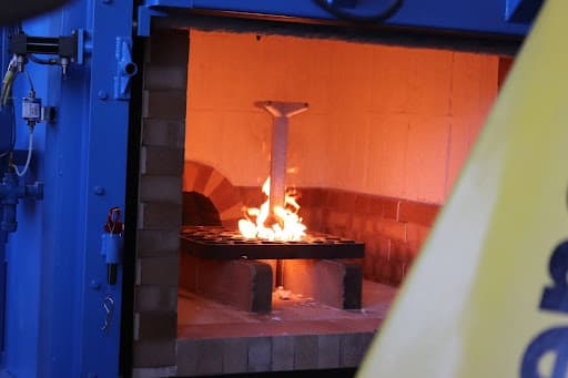
UNI’s burnout furnace (first image) and tree in flash fire (second image).
Casting
14. Follow your usual process for casting and finishing. For reference, UNI adopts the following steps:
14.1 Preheat the shell in a kiln at 345 °C (650 °F) for 30 minutes.
14.2 Pour the metal and let it cool until completely solidified.
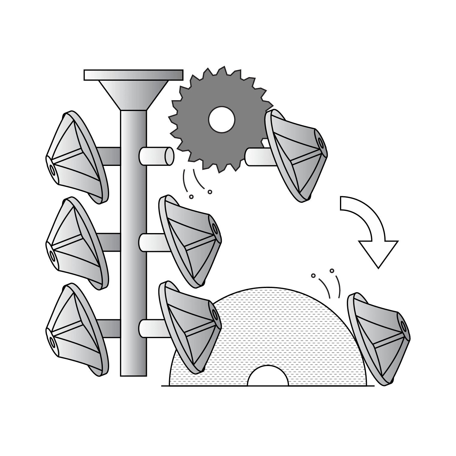
14.3 Remove the ceramic shell using a water or sand blaster. Chipping some of the shell off with a chisel is occasionally needed but should be avoided to preserve the part.
14.4 Separate the parts from the tree using a bandsaw or other tools.
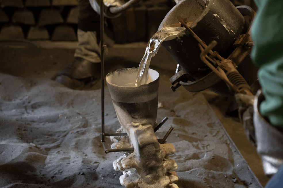

UNI’s team casts the metal into the ceramic shell (first image) then allows it to cool (second image).
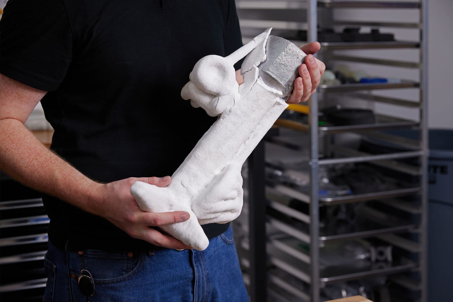
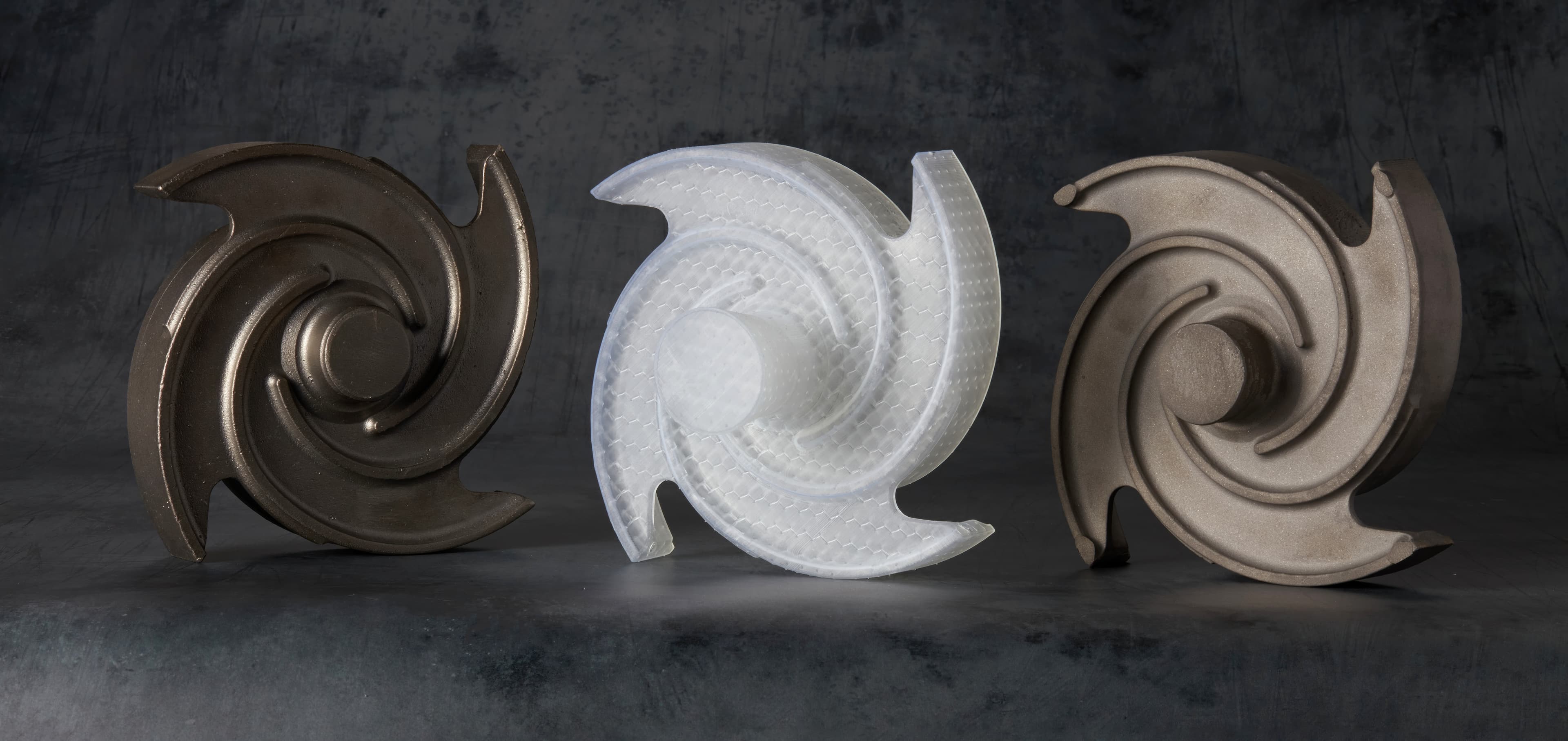
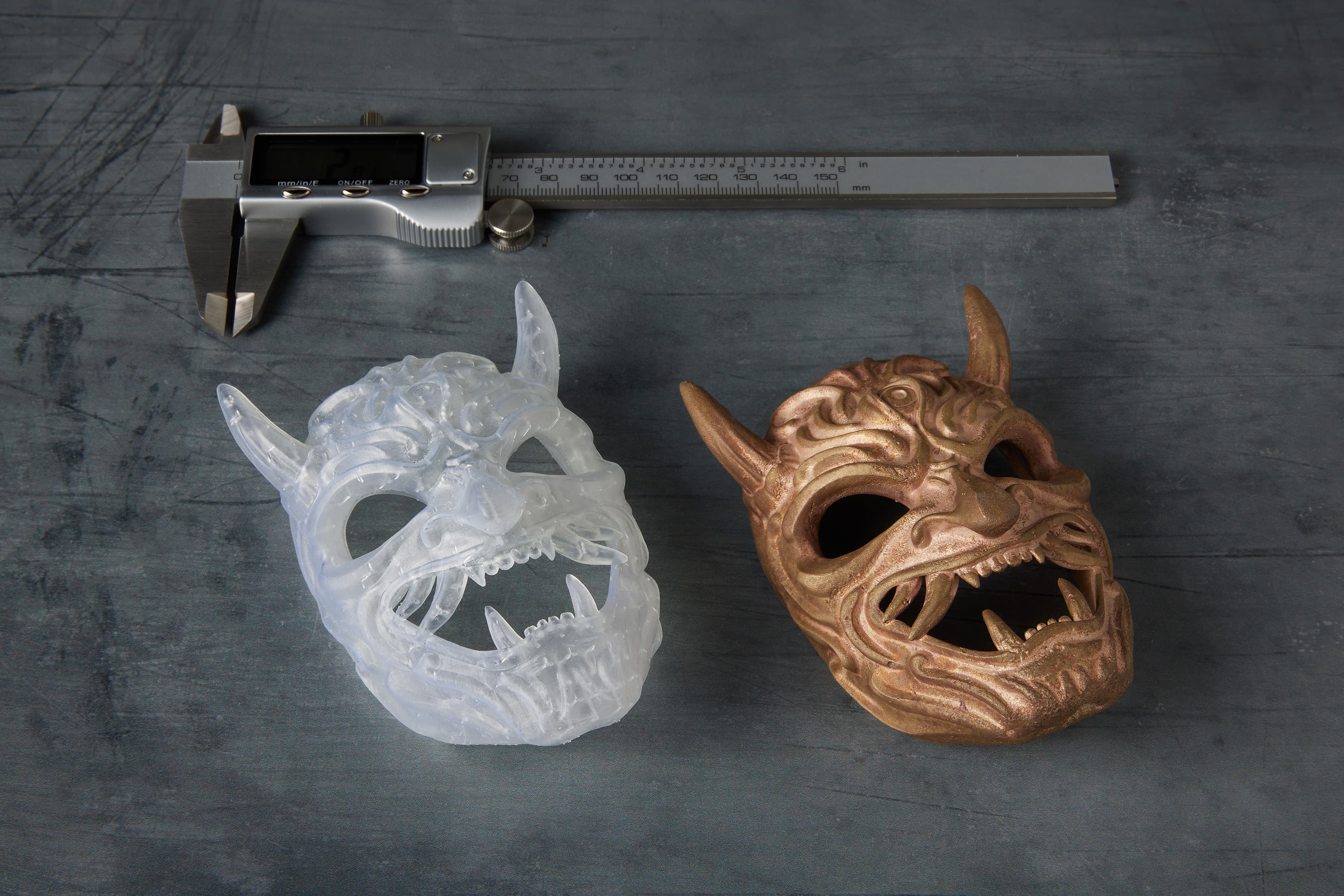
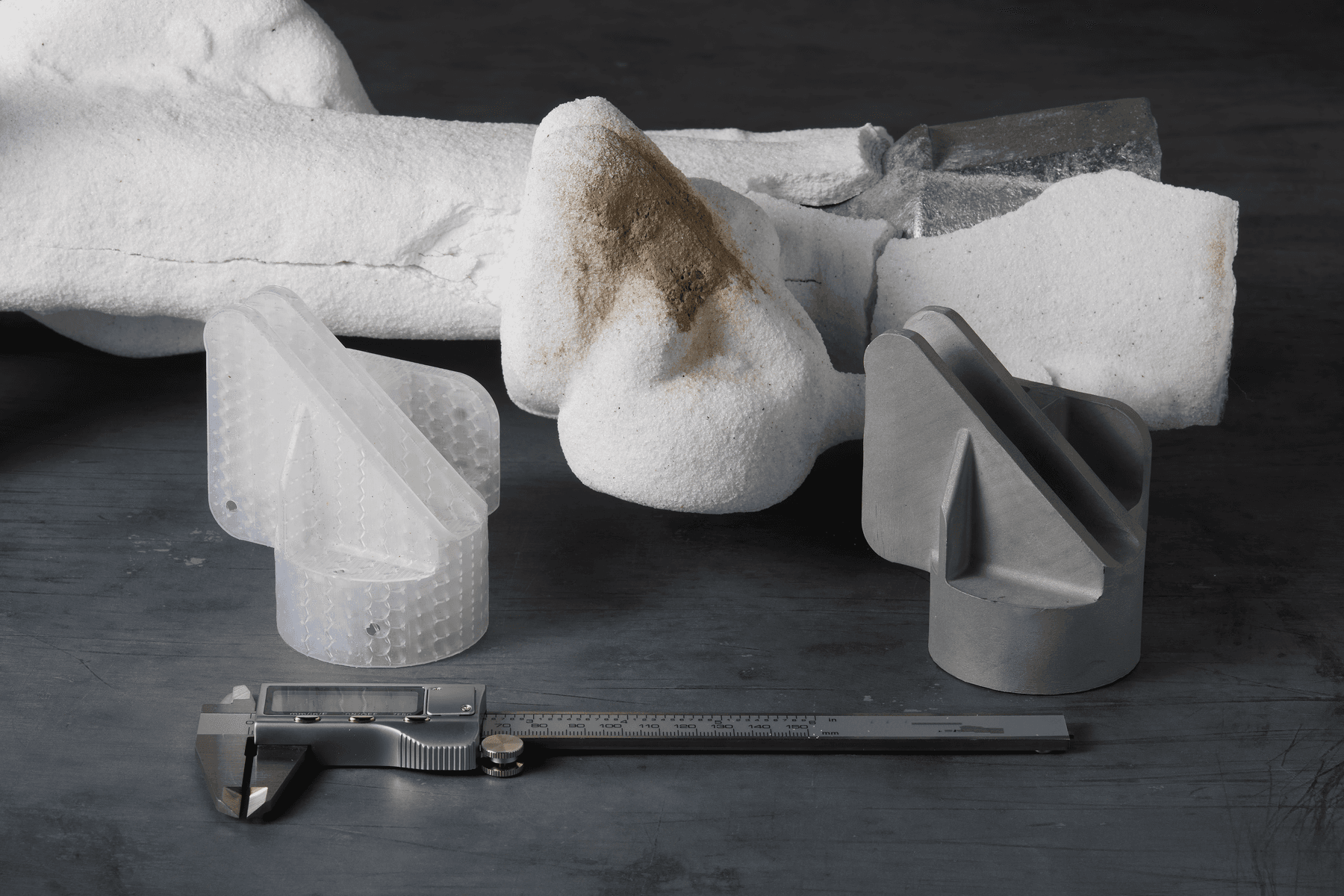
Once the full part is cool, the shell can be broken off (first image). The final part is then revealed (second image, alongside the initial pattern).
Conclusion
This report shows that 3D printed patterns can be used to lower costs and lead time in investment casting for rapid prototyping, quick turnaround, or limited production parts. Because it is a toolless fabrication method, 3D printing addresses key challenges associated with metal tooling in traditional casting processes. It enables on-demand tool fabrication, quickly and cost-effectively while increasing design freedom.
By adding 3D printing to the traditional foundry workflows, manufacturers can be more responsive to customer demands, delay investments in hard tooling, and validate designs cost-effectively. With Formlabs SLA 3D printers and Clear Cast Resin, several foundries were able to reduce tooling costs by up to 90% and lead times by several months, with only minor modifications to their casting workflow and minimal upfront investment.
Do you have questions about using an SLA printer for investment casting or other engineering and manufacturing applications? Reach out to our solutions specialists to try one of your pattterns in Clear Cast Resin.
Formlabs customers are eligible for a 35% discount on Materialise Magics.
Request a Materialise Magics trial now to access the discount.
Appendix: Physical Characterization of Formlabs Resins
Summary of Characterization
In the process of developing and validating materials for investment casting, Formlabs partnered with the Foundry 4.0 Center from the University of Northern Iowa (UNI). UNI tested and characterized Formlabs’ SLA ecosystem, focusing on two main materials, a beta version of Clear Cast Resin and Biomed Clear Resin. Through the testing, UNI was able to tune the design parameters to develop a qualified and easy-to-adopt process for 3D printing sacrificial patterns. The results are shown in comparison with popular competitor resin. Testing performed by UNI included testing compression, flexural strength, ash content, and thermal expansion. Formlabs also tested trace material contents to ensure compatibility with the casting process. The testing determined that the best candidate material was Formlabs’ beta Clear Cast Resin, which was cast in several test geometries prior to validating the material with the processes fully discussed in this white paper. The reason for this was its unique blend of low ash content, low crush strength, and high flex strength, all while maintaining a low enough CTE to minimize risks of damaging shells during burnout.
Compression Strength
Sample Characteristics
Nine geometries were evaluated with various outer shell wall thicknesses and lattice dimensions. The sample characteristics are shown in table 1. These were intended to sweep the range of possible prints in order to find the best blend of compressive strength and printability.
|
Sample ID |
Wall thickness (mm) |
Leg thickness (mm) |
Leg length (mm) |
|
A |
1 |
0.5 |
3 |
|
B |
1 |
0.75 |
3 |
|
C |
1 |
1 |
3 |
|
D |
0.75 |
0.5 |
3 |
|
E |
0.75 |
0.75 |
3 |
|
F |
0.75 |
1 |
3 |
|
G |
0.5 |
0.5 |
3 |
|
H |
0.5 |
0.75 |
3 |
|
I |
0.5 |
1 |
3 |
Table 1. Sample characteristics.
Testing:
58 samples were tested for compression strength in the above geometries, three unit of each geometry, the average of which is shown in the graph, along with a representative sample printed with the standard quick cast process. The results show that while the beta Clear Cast Resin has a higher compression strength than the competitive process at the geometry of part B, it is able to be dramatically reduced by slightly changing the wall thickness. Due to the low force and high accuracy of the Formlabs printers, there is no quality reduction at these geometries, therefore a thinner geometry is selected to continue forward.
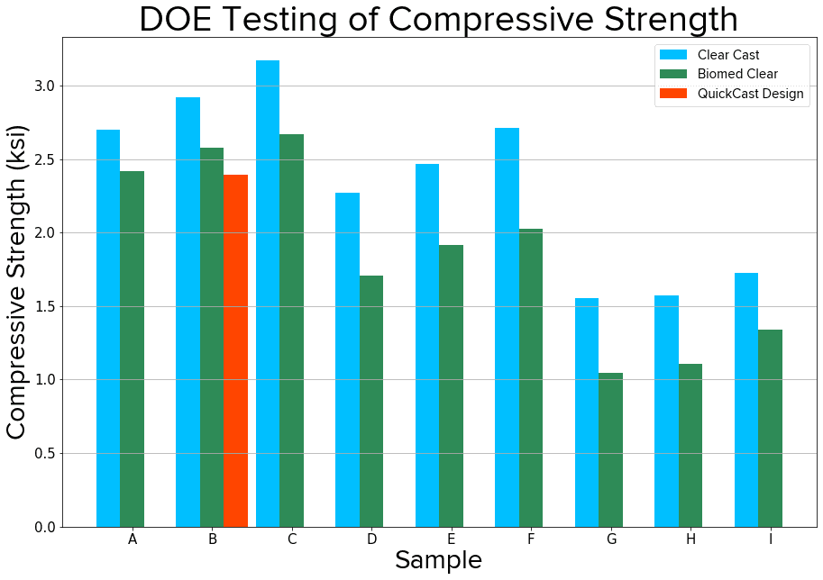
Graph 1: Average compression strengths for each sample geometry and each resin.
Flexural Strength
Four samples of each material were tested for flexural strength using ASTM D790 with standard sample geometry. The results show that both Formlabs materials have superior flexural strength, which translates to a more durable part that can withstand more rough handling throughout the process.
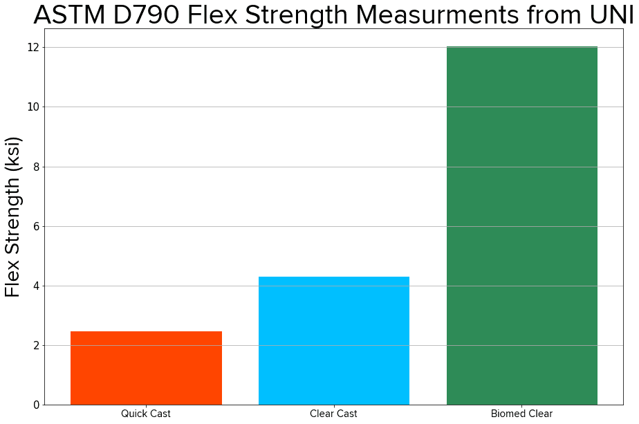
Average flexure Stress (ksi) for each material.
Ash Content
Three samples of Formlabs beta Clear Cast Resin and three samples of BioMed Clear Resin were tested according to ASTM standard D2584. This entails taking a 5 g sample, measuring it to the nearest mg, and completely burning it out in a muffle furnace. The remaining ash is again measured, resulting in the following data, which shows the performance of the two different Formlabs materials.
|
Sample |
Ash Content |
|
Formlabs beta Clear Cast Resin |
0.024% |
|
Formlabs Biomed Clear Resin |
0.006% |
Table 2: Average of the ash content for each material.
In addition, Formlabs performed elemental analysis on a sample of beta Clear Cast Resin, obtaining the following result. Note that there is some variation between batches, so this isn’t necessarily representative of every material.
|
Element |
Clear Cast Resin |
|
Antimony |
<10 ppm |
|
Detected Transition Metals (>10 ppm) |
Al, Cu |
|
High Concentration Transition Metals (>50 ppm) |
None |
|
Other detected inorganic materials >10 ppm |
Sn, Si, P |
Table 3: Trace element measurements on Formlabs’ beta Clear Cast Resin
Thermal Expansion
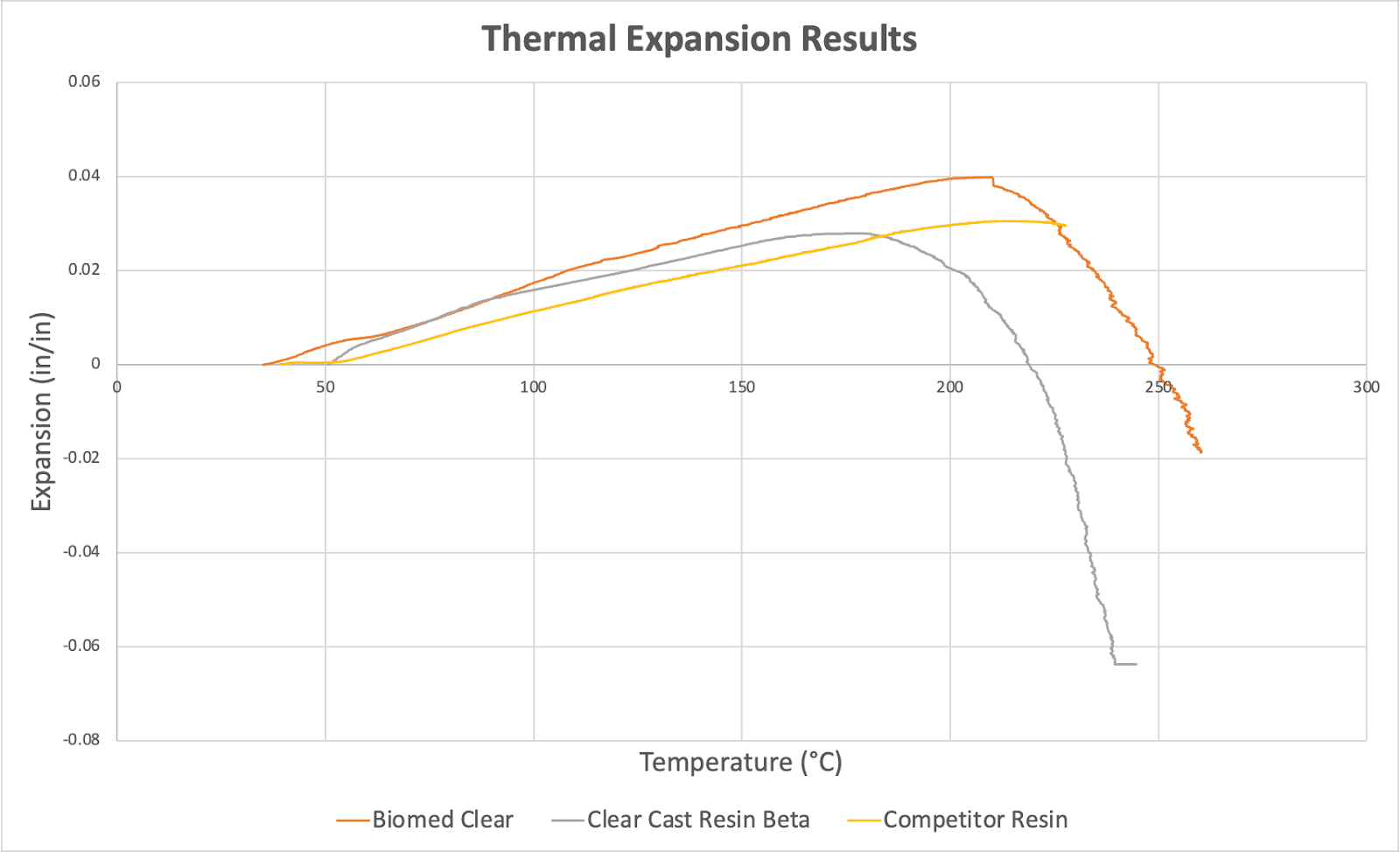
Thermal expansion results from a dilatometer.
UNI tested several different target geometries for their thermal expansion results, the graph shows a direct comparison between the recommended Formlabs geometry and competitor geometries. This testing showed the key issue with BioMed Clear Resin to be the thermal expansion of the resin but also showed that the beta Clear Cast Resin from Formlabs had a lower final expansion than the main competitor resin did, making it less likely to crack shells.
These results were confirmed by casting trials, in which beta Clear Cast Resin was cast many times without damaging the shell during burnout, however, some of the BioMed Clear Resin parts did cause the shell to crack.