
At SIGGRAPH 2015, an amazing technical demonstration made waves by showing a way to add full color graphics to solid-color 3D prints.
Computational Hydrographic Printing, presented by Yizhong Zhang, Chunji Yin, Changxi Zheng, and Kun Zhou at ACM SIGGRAPH 2015.
The software’s authors haven’t made any software available yet, but you can replicate some of their technique by creating a simple simulation in Blender and applying the result to a 3D printed model with immersion printing.
Immersion printing is typically used to customize objects like game controllers and guitars with graphic patterns. The object is dipped into a water bath with a floating, partially dissolved colored film, which wraps around the object and transfers the graphic to the surface. Objects with compound curves are challenging to color with graphics any other way!
3D models are often designed with image textures, which are wrapped around the model using a “UV map.” By printing a modified UV map onto hydrographic transfer film, we can apply a diffuse texture to the surface of the 3D print. Unlike normal repeating-pattern hydrographics, a UV texture needs to be accurately positioned on the model. This requires a way to simulate and predict the behavior of the hydrographic film as it wraps around the model.
Table of Contents:
Step 1: Make a Transfer Tank
In order to build an accurate simulation, you need to know the exact position of the floating film. Building an immersion printing transfer tank into an existing 3D printer is a convenient way to precisely dip the model.

We used a Form 2 printer and repurposed an old resin tank, which was cleaned with the silicone layer removed. We laser cut a small water tank out of acrylic, assembled with solvent, and glued into the empty resin tank. This design ensures that if water spills, it will spill into the tank instead of the printer.
This technique also works with the Form 1+, because you can use OpenFL to drive the Z axis motion. Our water tank includes a printed barrier that helps prevent the film from sticking to the side walls of the tank.
Step 2: Simulate Hydrographics
In the immersion printing process, hydrographic film floats on the surface of a water bath through surface tension. Blender doesn’t natively simulate surface tension, so our setup models the hydrographic film with a cloth simulation, which interacts with a collision object (the 3D-printable, UV-mapped mesh) and is frictionlessly “floated” between two force field entities. By baking the diffuse texture of your model to the final frame of the simulated film, you can pre-distort the texture map so that it will un-distort as the object is dipped.
Download the .blend file of the setup with reasonably good settings for the cloth simulation. If you try it out and find better settings, send us a line!
Blender Workflow:
- Import the UV-mapped model, position it centered above the tank, and add collision physics.
- Keyframe the location of the model along the Z axis over 50 frames, starting fully above and ending fully below the film.
- Run the simulation. The film should behave like a cloth being dragged down wherever the collision model touches it, eventually wrapping around the midpoint of the object.
- Duplicate the film object on the last frame, and convert the simulation to a mesh (alt + c).
- Select the collision object, then the distorted film object, and Bake “Selected to Active.” The color information of the Print object will transfer to the Film object. Note: if you get a blank image, you may need to reverse the normals of the film object.
- Save the baked image texture over the blank file.
- Verify the results by running the simulation again. Import your baked texture as the UV texture map of the film. If the texture “slips” across the surface of the model, inaccuracies will appear during the real dipping process.
Step 3: Dip the Graphics
We attached the model to a printed quick-mount. The model for the mount can be re-used. The center of the quick mount is the same as the center of the model, and the center of the pool. This ensures that the model registers to the same location every time.
Dipping Process:
- Print your graphics on PVA hydrographics film. Use an inkjet printer with pigment-based ink. Make sure to scale the 2D print correctly based on the rendered resolution of the baked texture and the simulated size of the film.
- Coat the film with fixing solution using a Preval sprayer to and let it dry for at least 10 minutes.
- Fill the water tank with water between 28 and 30 degrees C.
- Lay the film ink-side-up on the surface of the water. Don’t touch it after you place it on the water. If there are air bubbles under the film, you can quickly blow on them to move them away. The film will wrinkle, and then become smooth.
- Spray the film with activator. Using less activator will make the film stronger, and less likely to fill corners. Using more activator will make the film weaker and fill interior corners better, but can make colors less intense and reduce the accuracy of the simulation. Using too much activator will dissolve the image.
- Dip the part into the film. You can use OpenFL to move the Z axis if you’re using the Form 1+ printer. The optimal dipping speed is about 2-5 mm per second.
- Rinse the part under water to remove the excess film. Don’t rub the part. Let it air dry for an hour.
Test Cases
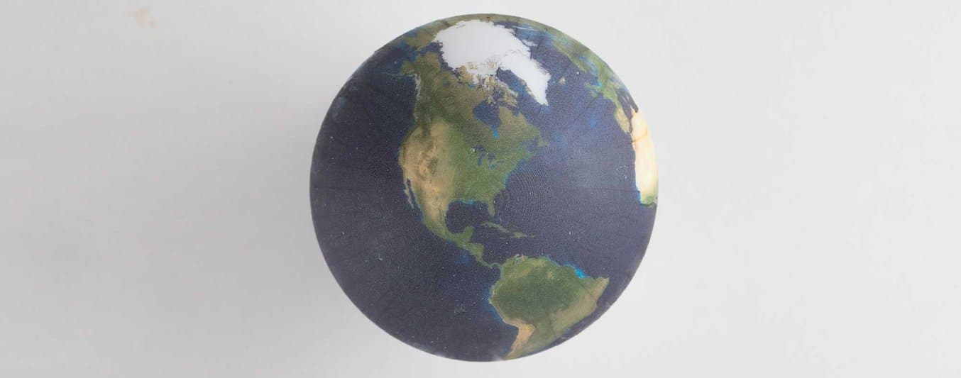
Spherical Mapping

Objects with gradual curves, such as spheres, work very well. The result closely matches the simulation. Some folding and wrinkling of the film is unavoidable with compound curves like spheres, but this excess film can usually be gently washed off in water.
Complex Surface with Undercuts and Large Z Breaks

The frog model pictured has challenging geometry with big variations in slope. Surprisingly, it worked quite well.

Some areas are too concave to receive any coloring, such as where the legs meet the frog. This is predicted by the simulation - we can see that the cloth stretches over those regions but doesn’t touch them.
Flat Projection

Flat models need to be oriented at a slight angle to the water to prevent air bubbles from forming. Alignment between the model and the floating film is very important for a good result, and the film has a tendency to shift on the surface of the water.
See what you can create with a Form 2
Explore the materials to discover the one that fits your needs.
Request a Free Sample

Limitations
Rather than modeling the hydrographic film as a viscous sheet, we are treating it as a very flexible, buoyant cloth. The simulated cloth will never break apart, while the real film will. Depending on the cohesivity of the film, the graphic can be applied up to and past the midpoint of the model, but it will fail to fill areas with large breaks in elevation. Hydrographic dipping only works well on convex objects. Overhangs, interior corners, and regions of deep concavity will be missed by the draping film. This effect can be adjusted by applying more or less activator. More activator will make the film weaker and prone to breaking, but more likely to fill gaps.
The biggest challenge we saw is aligning the model with the film, which is prone to shifting and rotating slightly. Our setup isn’t perfect - if the model could be translated in X and Y relative to the tank, and even rotated, it would be possible to get better registration every time. A hydrographic tank built into a CoreXY cartesian printer would be great for controlling and adjusting registration.
Share Your Results
We’d love to hear from anyone who sets out to try computational hydrographics themselves!