Required supplies:
Formlabs:
- Lead screw cleaning tool
- Magnalube-G grease or equivalent high-temperature PTFE-based grease
Third-party:
- 2.5 mm hex driver
- 2 mm ball-end hex driver
- Applicator stick for grease
- Paper towels
- Cotton swabs
- Nitrile gloves


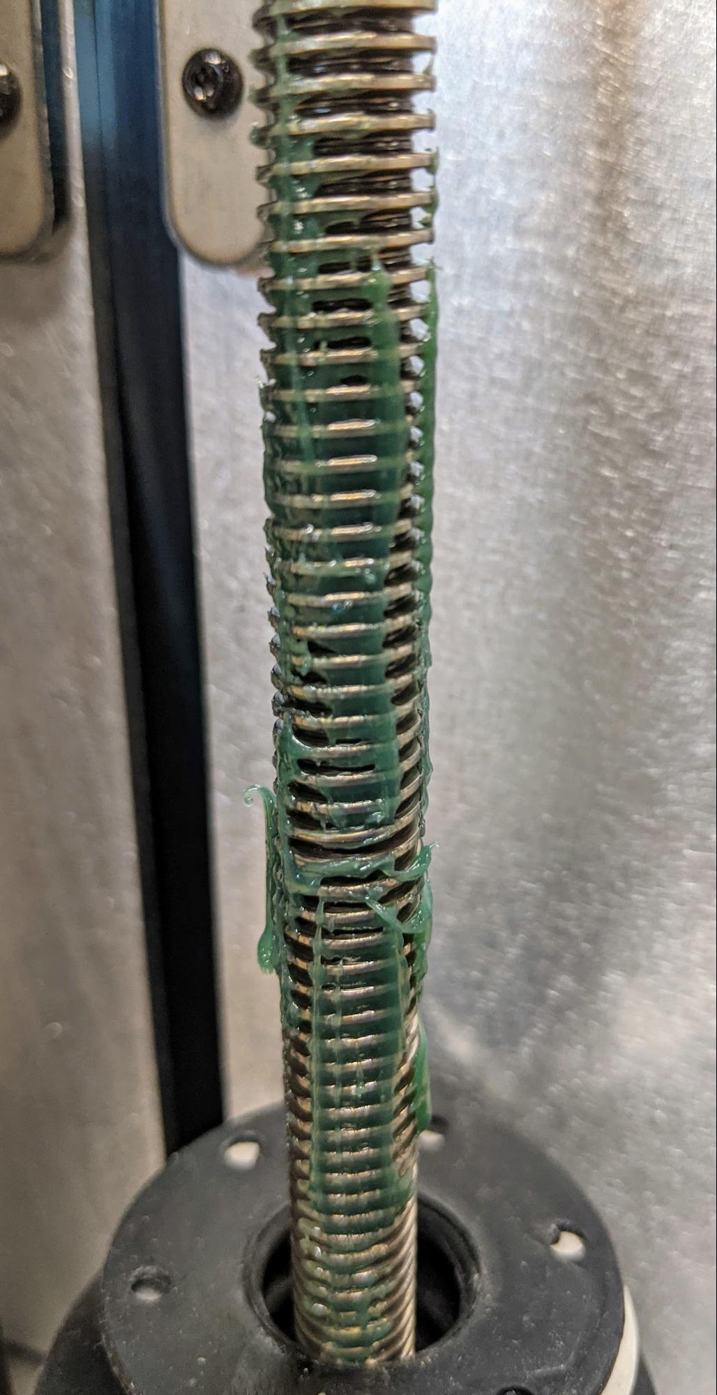
Over time, the nut on the build chamber’s Z-axis lead screw can degrade and leave a black residue in the grease on the lead screw. Loose powder can also contaminate the grease. This debris can cause the print bed to stall or generate noise during printing.
Use this guide to clean and lubricate the Z-axis lead screw on a Fuse 1 generation build chamber.
Required supplies:
Formlabs:
Third-party:
Estimated time: 30 –45 minutes
Vorbereitung des Arbeitsbereichs
Overview: Prepare the build chamber and a dust-free workspace for cleaning and lubricating the Z-axis lead screw.
Step 1: Empty the build chamber
If the build chamber has recently been used for a print and contains a powder cake, empty the build chamber using a Fuse Sift. Even if the build chamber is already empty, fully raise the print bed using the controls on the Fuse Sift or the Motor Moves menu on the printer touchscreen.
Step 2: Vacuum the build chamber
Use the vacuum attached to the Fuse Sift to clean the build chamber. If the build chamber is inserted into the Fuse Sift, push the Vac button on the control panel or tap the vacuum hose icon on the touchscreen to turn the vacuum on. Vacuum the print bed and the top of the build chamber to remove any loose powder and prevent contamination of the lead screw grease or your workspace. If the build chamber is not currently inserted into the Fuse Sift, remove the vacuum hose from the port on the side of the Fuse Sift so that it can reach the build chamber, then turn on the vacuum.
Step 3: Prepare the workspace
Clear a workspace around your build chamber. Ensure that the workspace is well-ventilated and free of dust.
Entfernen des Rückgehäuses der Konstruktionskammer
Overview: Remove the rear shell of the build chamber to access the Z-axis lead screw.
Step 1: Remove the build chamber handle screws
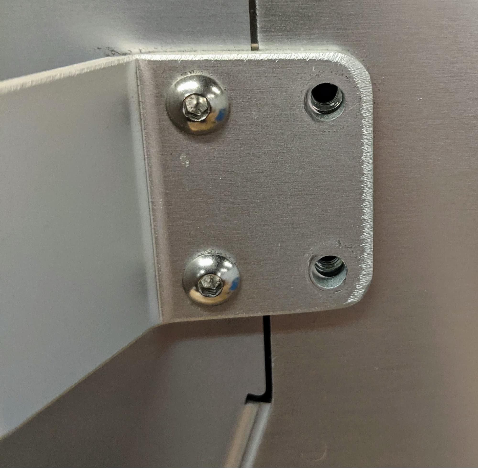
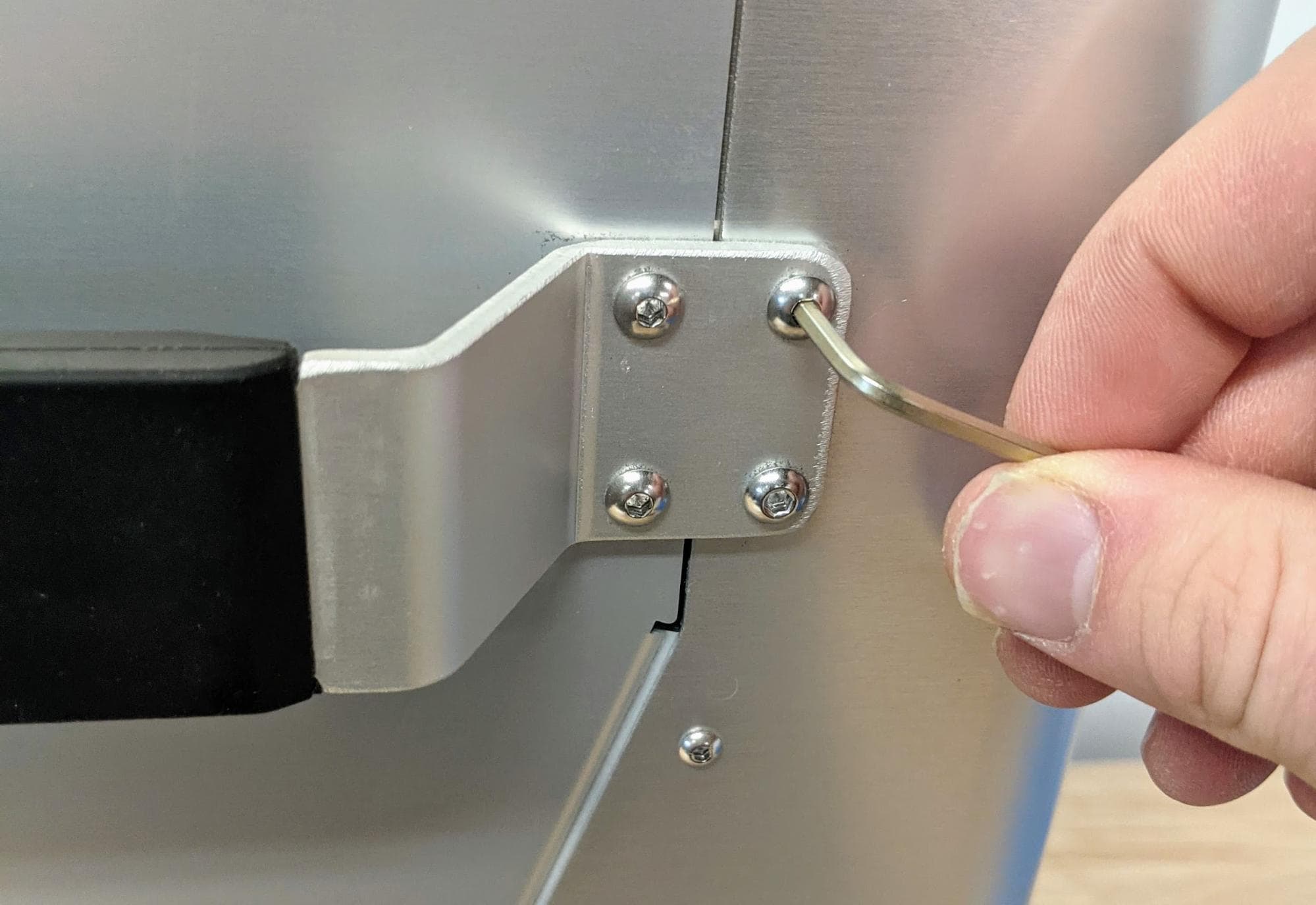
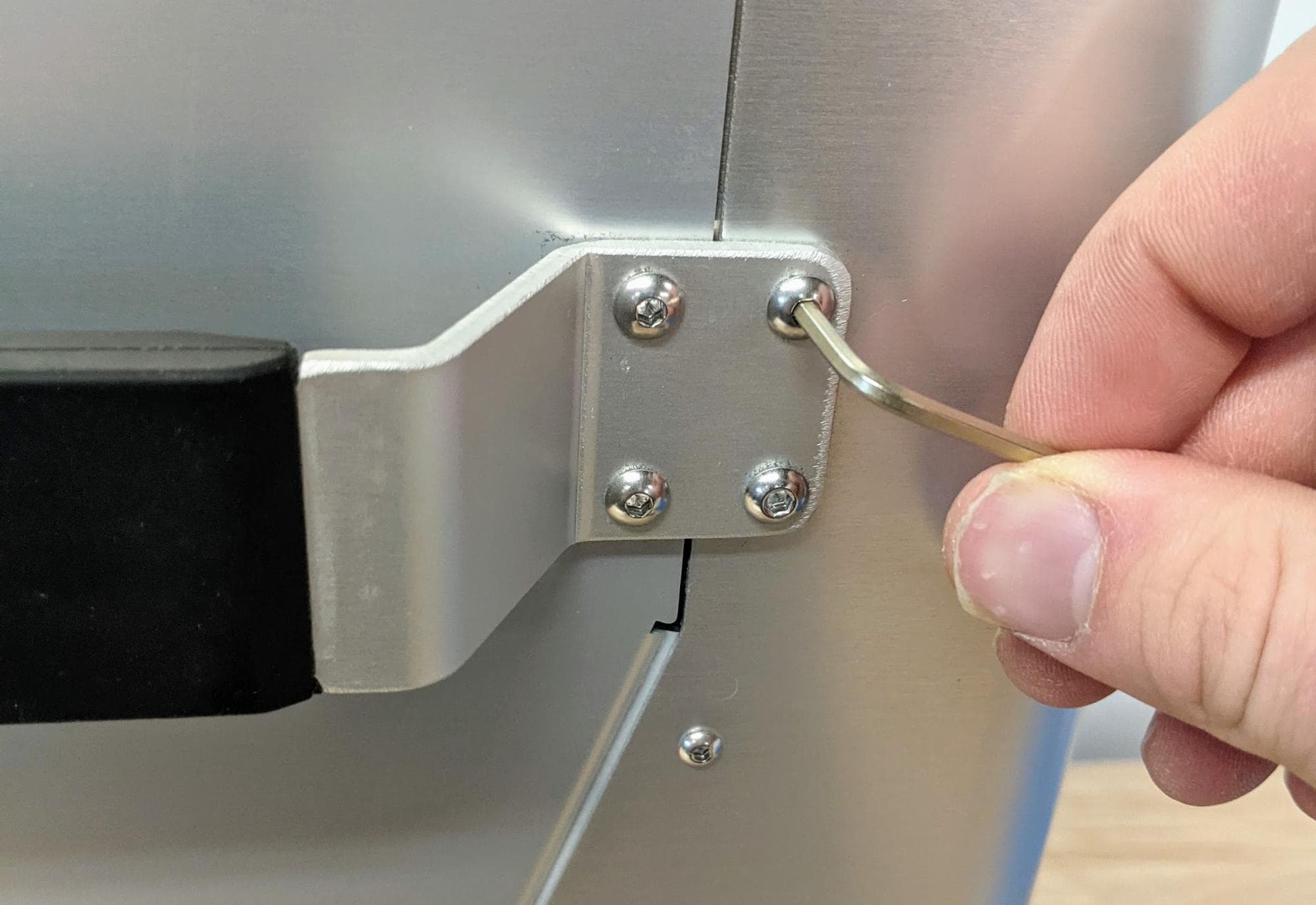
Using a 2.5 mm hex driver, loosen and remove the two M4 × 10 mm screws securing the build chamber handle to the rear shell. Leave the other two screws in place. Repeat on the other side of the build chamber.
Step 2: Remove the rear shell screws

Use a 2 mm hex driver to remove the M3 × 6 mm screws securing the rear shell to the build chamber. There are 15 screws in total: six screws on the left and right sides of the build chamber and three screws on the rear. Set the screws aside.
Step 3: Remove the rear shell
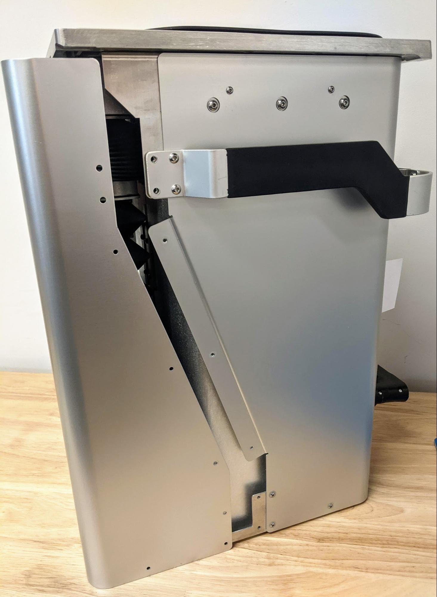

Grip the rear shell and pull it away from the build chamber. Set the rear shell aside.
Reinigung der Z-Achsen-Leitspindel
Overview: Remove the contaminated grease from the Z-axis lead screw.
Step 1: Remove the lower rubber lead screw baffle
The lead screw is protected by two rubber baffles, secured to either side of the housing that holds the lead screw nut. When the print bed is at the top of the build chamber, the upper baffle is fully compressed. The lower baffle must then be removed to access the lead screw for cleaning and relubrication.
Use a 2 mm ball-end hex driver to loosen and remove the four M3 × 6 mm screws securing the lower baffle. These screws are accessible from the bottom side of the lead screw nut housing, which sits between the two baffles.
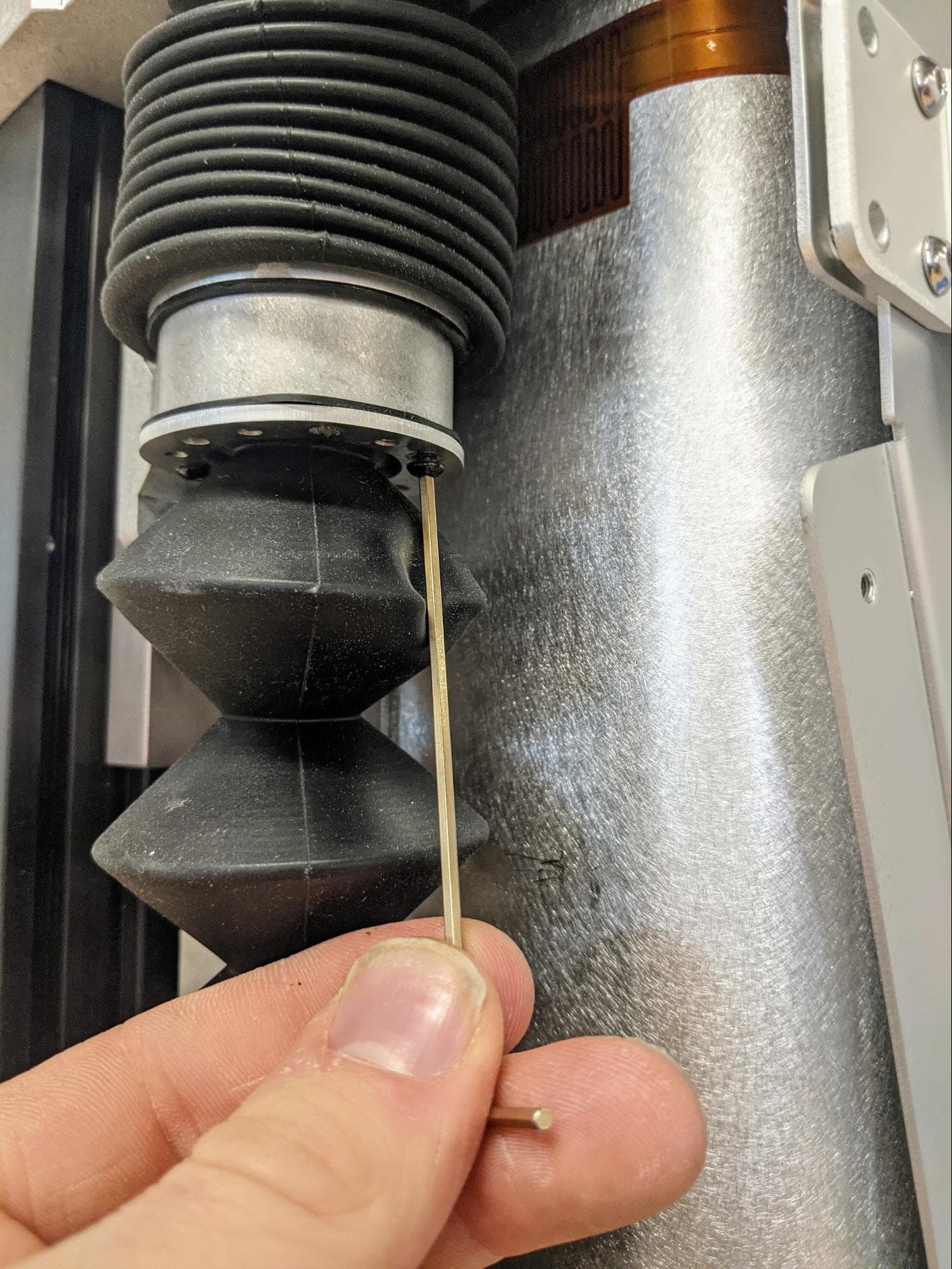
Repeat for the four screws on the bottom of the build chamber, which secure the lower baffle to the body of the build chamber. Set the screws aside.
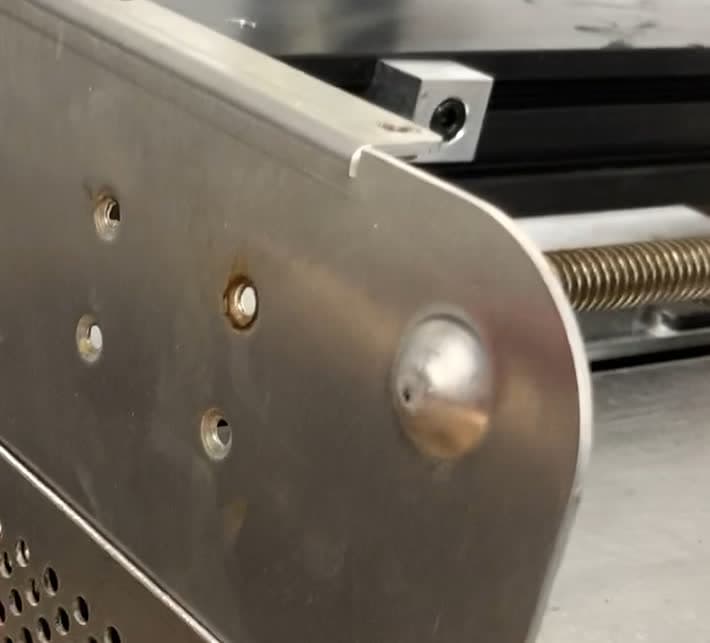
After the screws have been removed, compress the lower baffle and slide it off of the lead screw.
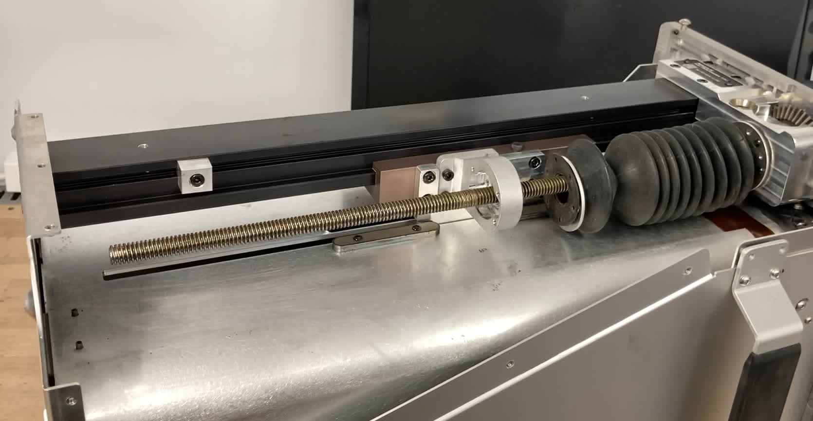
Step 2: Wipe the Z-axis lead screw
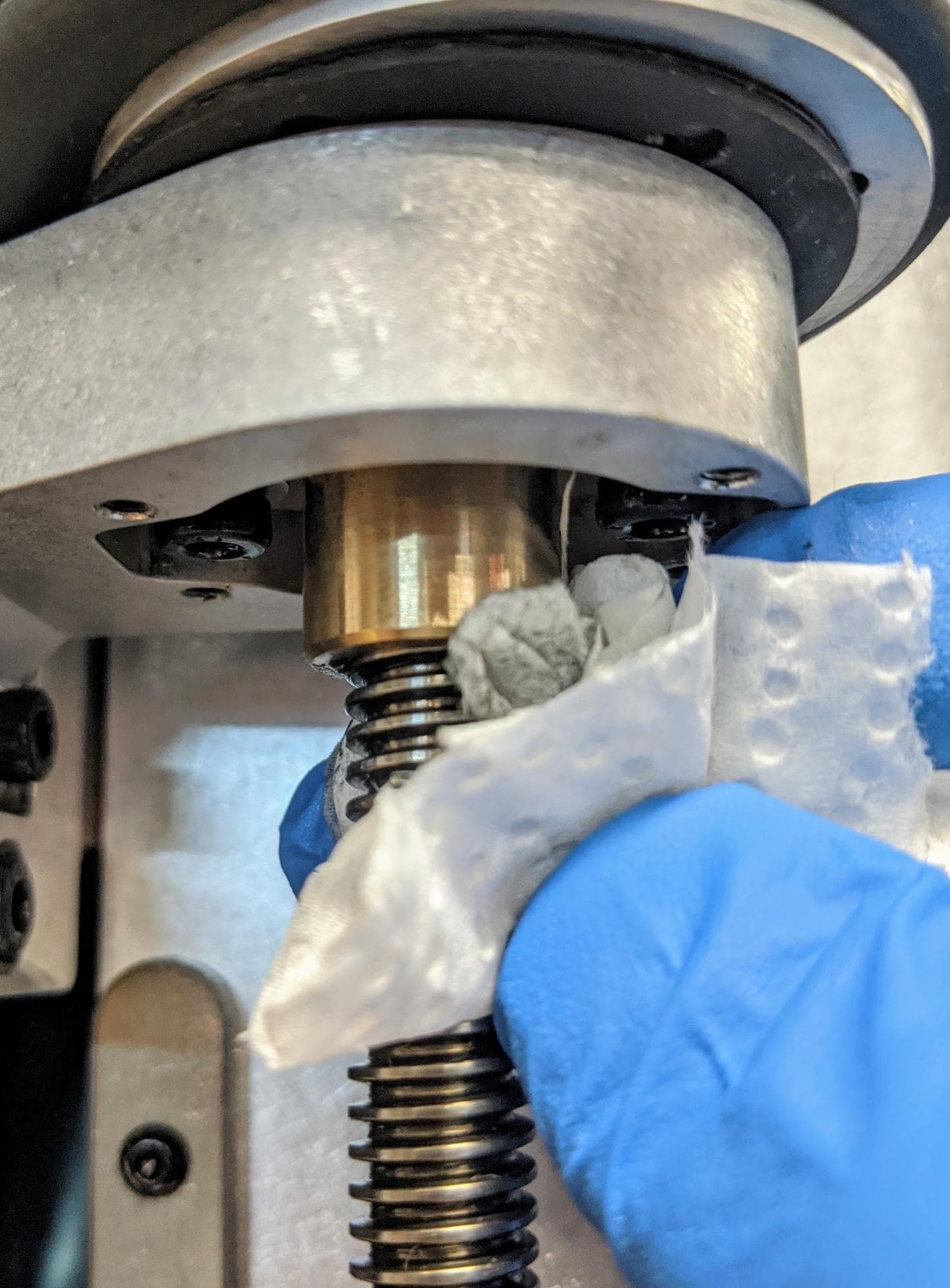
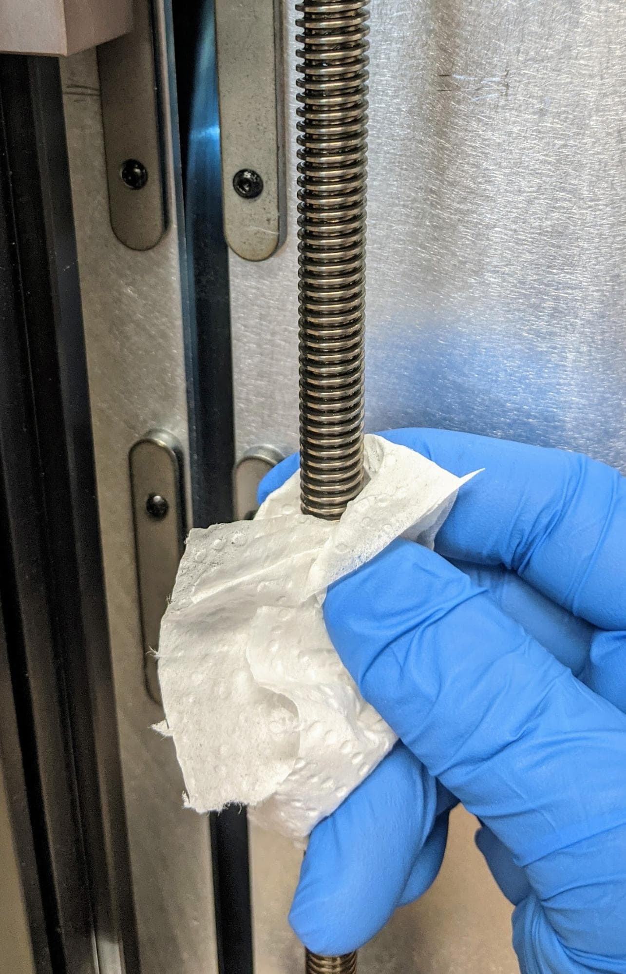
Gently wipe down the lead screw and lead screw nut with a dry paper towel and cotton swabs.
Warning:
PTFE-based grease may cause skin irritation or an allergic skin reaction. Wear gloves when interacting with the Z-axis lead screw.
Step 3: Attach the lead screw thread cleaning tool
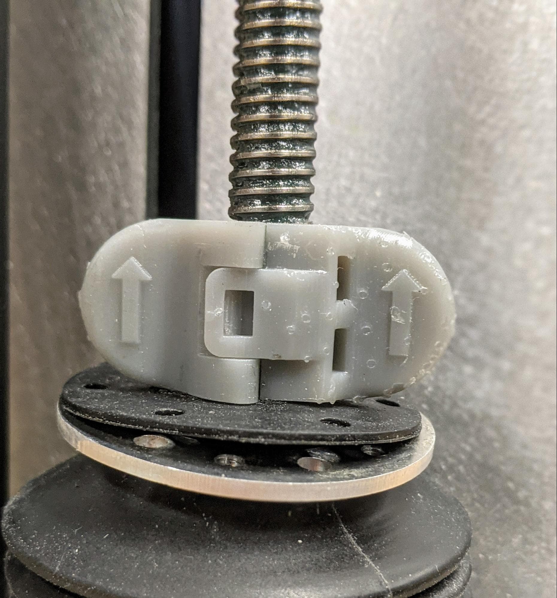
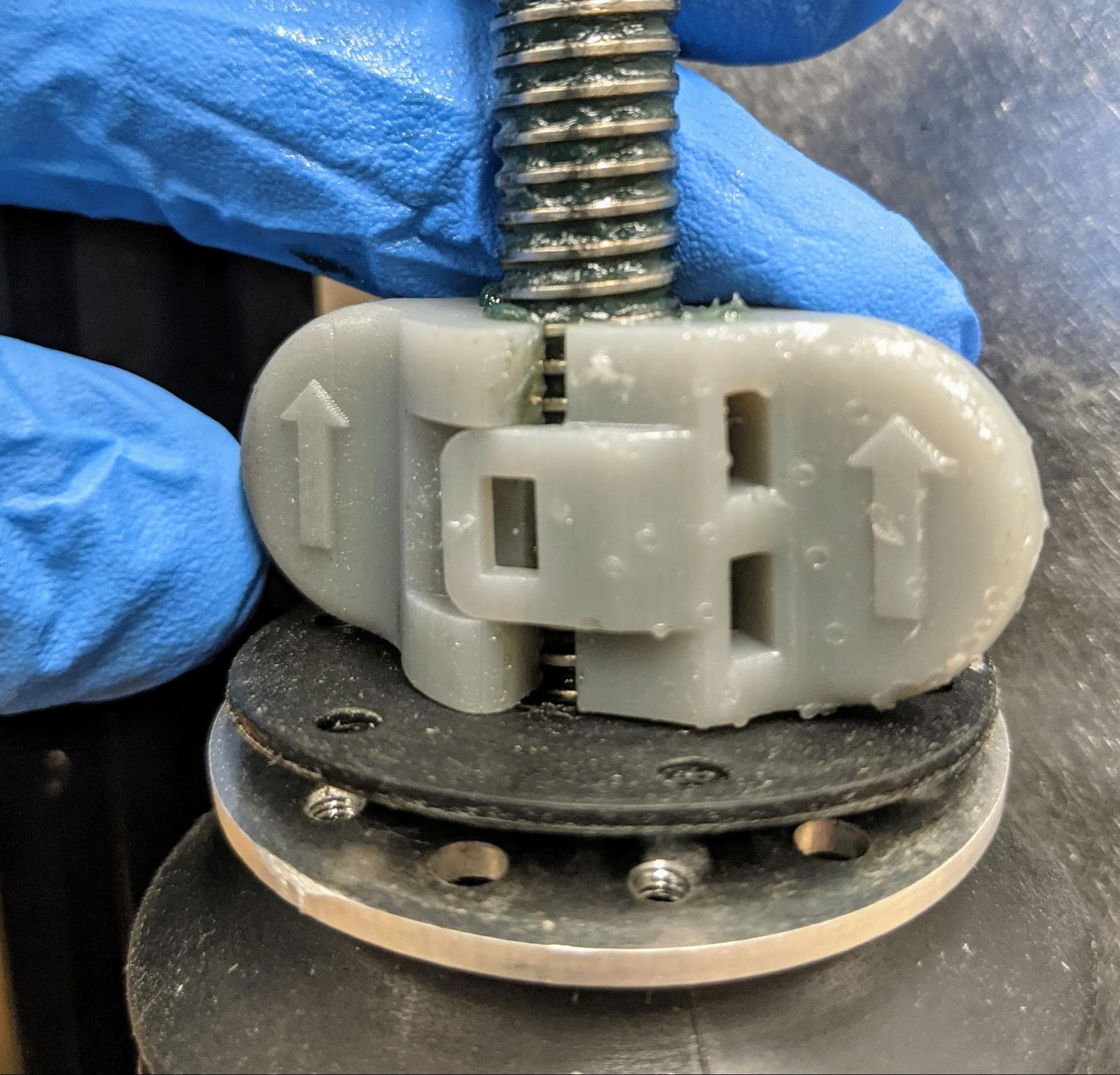
Seat one half of the lead screw thread cleaning tool on the threads at the bottom of the lead screw with the embossed arrow pointing up. Snap the other half of the tool onto the first half, fully enclosing the lead screw. The tool should snap closed without significant resistance and should spin freely on the lead screw.
Step 4: Rotate the lead screw thread cleaning tool
Rotate the thread cleaning tool so that the tool moves upward, in the direction of the arrows. Continue rotating the tool until it reaches the lead screw nut.
Step 5: Remove the lead screw thread cleaning tool
Unclip the lead screw thread cleaning tool. Remove the tool from the printer cavity.
Step 6: Wipe the Z-axis lead screw
Gently wipe down the Z-axis lead screw with a dry paper towel.
Schmieren der Z-Achsen-Leitspindel
Overview: Apply new lubricant to the Z-axis lead screw.
Warning:
PTFE-based grease may cause skin irritation or an allergic skin reaction. Wear gloves when interacting with the Z-axis lead screw.
Step 1: Apply grease to the Z-axis lead screw
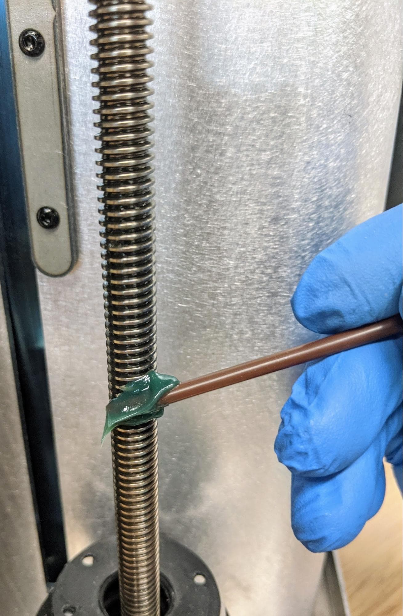
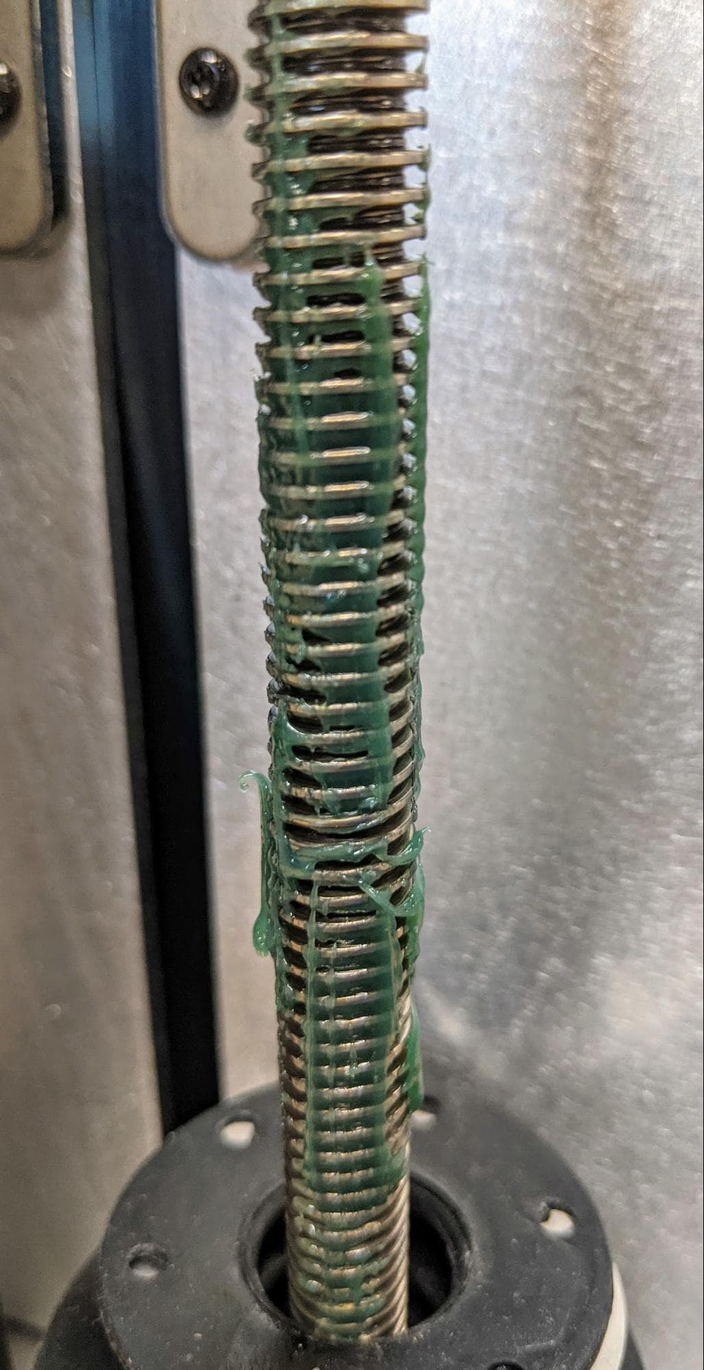
Place a small amount of grease on an applicator, such as a tongue depressor or coffee stirrer. Apply small amounts of the new grease along the length of the Z-axis lead screw.
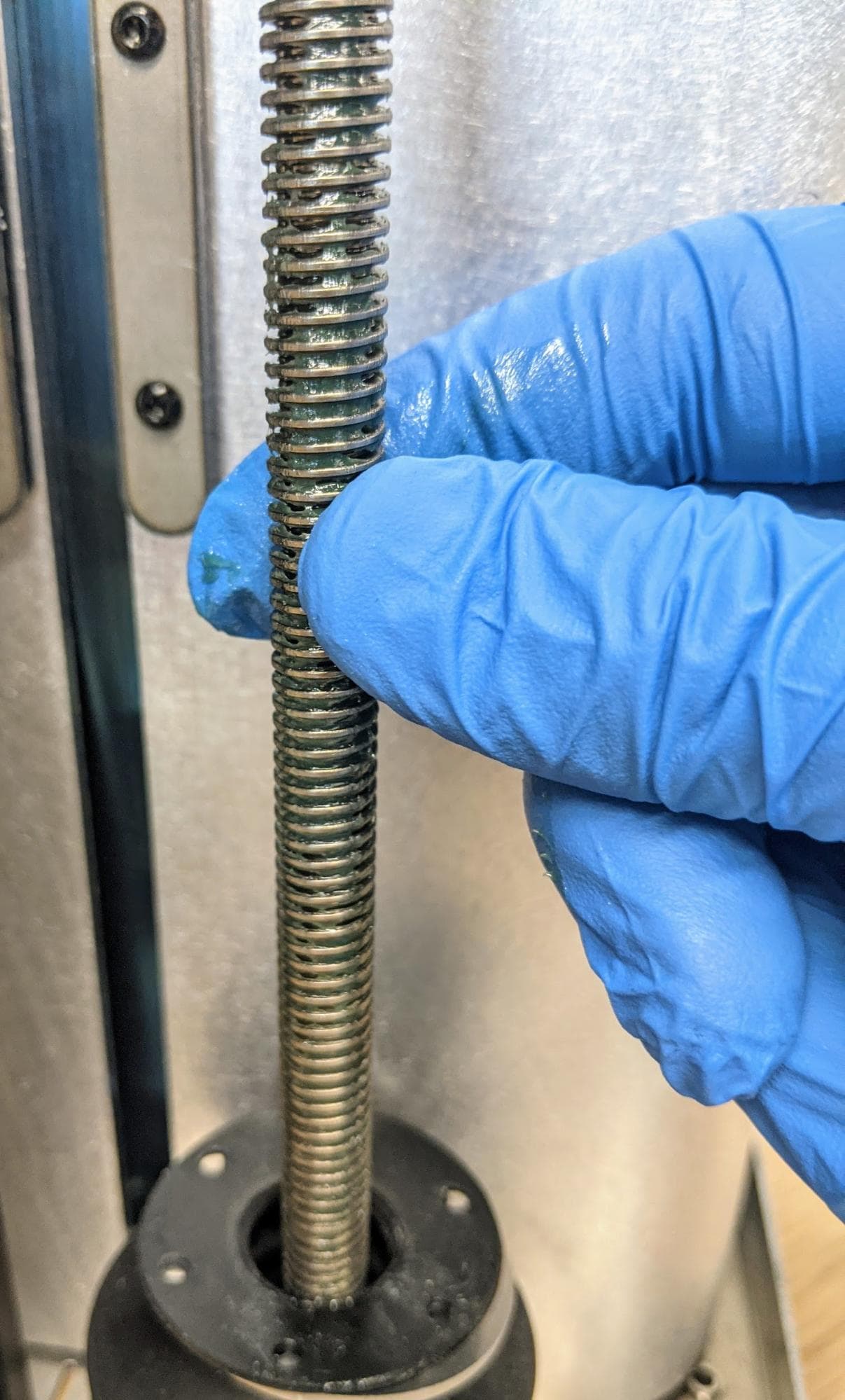
Using your gloved fingers, spread the grease along the Z-axis lead screw.
Wiedermontage des unteren Schutzblechs und des Rückgehäuses
Overview: After cleaning and lubricating the Z-axis lead screw, reinstall the lower baffle and the build chamber’s rear shell.
Step 1: Reinstall and secure the lower baffle
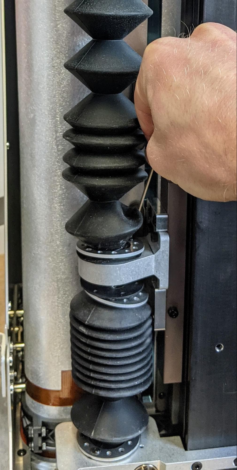
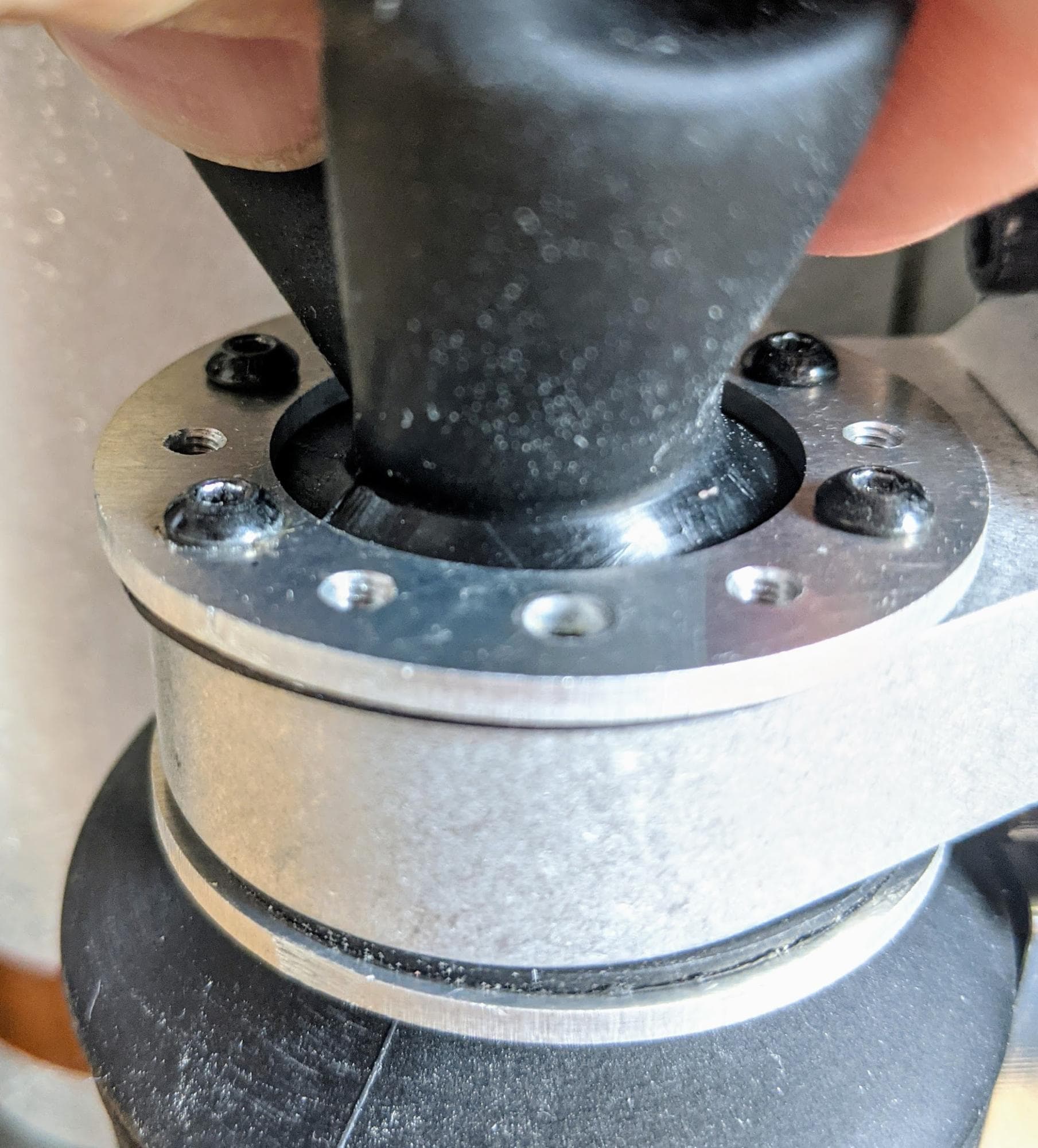
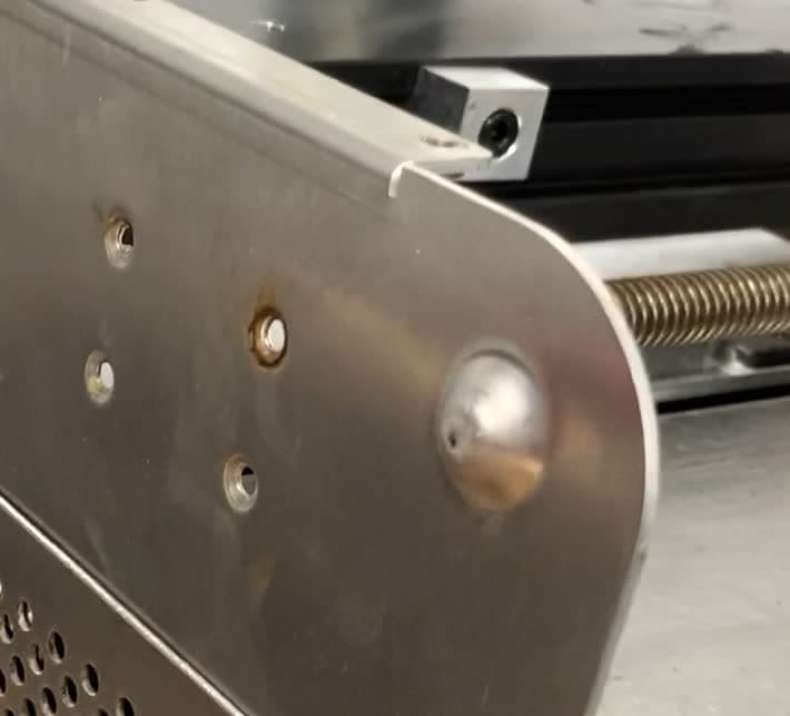
Turn the build chamber upside down and rest it on its top surface. Compress the lower baffle and slide it onto the lead screw. Align the unthreaded screw holes in the metal bellow flange with the holes in the lip of the rubber bellow and the threaded holes in the nut housing. Loosely thread four M3 × 6 mm screws through the unthreaded holes in the bellow flange and into the threaded holes in the nut housing. Use a 2 mm ball-end hex driver to tighten the screws until finger tight. Do not overtighten. You may need to manually rotate the bevel gear to position the lead screw nut housing for easier access.
Repeat for the four screws securing the lower baffle to the bottom of the build chamber.
Step 2: Replace the rear shell
Slide the rear shell onto the build chamber, ensuring that the screw holes in the rear shell align with the corresponding holes in the build chamber frame and handle.
Step 3: Secure the rear shell
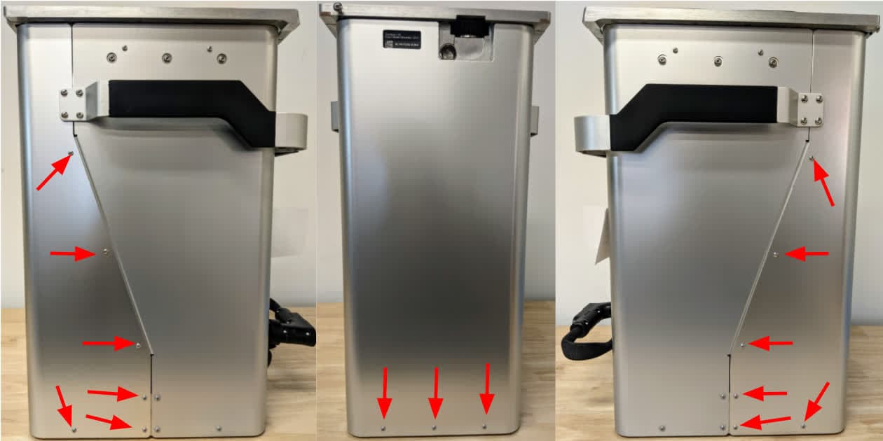
Thread the 15 M3 × 6 mm rear shell screws into their screw holes in the rear shell: six each on the left and right sides and three on the rear. Use a 2mm hex driver to tighten the screws until finger tight.
Thread two M4 × 10 mm screws into the screw holes on one side of the handle. Use a 2.5 mm hex driver to tighten the screws until finger tight, securing the handle to the rear shell. Repeat on the other side of the build chamber.
Abschließen der Reparatur
Overview: After reinstalling the build chamber’s rear shell, perform final checks.
Step 1: Spread the lead screw lubricant
Insert the build chamber into the Fuse 1 generation printer or Fuse Sift. Close the build chamber latch and connect the build chamber plug to the machine. Move the print bed up and down using the Fuse Sift control panel or the Motor Moves menu on the printer to evenly spread the new lubricant along the build chamber lead screw.
Step 2: Test the build chamber
Insert the build chamber into the Fuse 1 generation printer and start a print. Monitor the build chamber to ensure that the print bed moves smoothly and without any unusual noises. Contact Formlabs Support or your certified service provider to share the results of the procedure.