Tipp:
In derinteraktiven Tour des Form 3 erhalten Sie eine 3D-Ansicht zahlreicher Komponenten, die unten beschrieben werden.


Tipp:
In derinteraktiven Tour des Form 3 erhalten Sie eine 3D-Ansicht zahlreicher Komponenten, die unten beschrieben werden.
Außenkomponenten
| Artikel | Beschreibung | Abbildung |
|---|---|---|
| Gehäuse | Fünf schützende Außengehäuse schützen die internen Komponenten des Druckers:
|  |
| Nivellierfüße | Jede Ecke des Druckers wird von einem Gummifuß gestützt, der in den Boden des Geräts eingeschraubt ist. Wenn Sie auf dem Touchscreen dazu aufgefordert werden, verwenden Sie die Nivellierscheibe, um die Füße einzeln zu erhöhen bzw. abzusenken, bis der Drucker ausreichend | eben steht. |
Displaybaugruppe
| Artikel | Beschreibung | Abbildung |
|---|---|---|
| Displaybaugruppe | Die Displaybaugruppe enthält den Touchscreen und die Displayplatine. Ein Flachbandkabel verbindet die Displaybaugruppe mit der Hauptplatine. |  |
| Touchscreen: | Die kapazitive LCD-Touch-Benutzeroberfläche zeigt Druckinformationen, Einstellungen und Fehlermeldungen an. |  |
| Display-Leiterplatte | Diese von der Hauptplatine getrennte Platine steuert den Touchscreen. |  |
| Displaykabel | Ein flaches, flexibles Kabel verbindet die Displaybaugruppe mit der Hauptplatine. |  |
Abdeckung
| Artikel | Beschreibung | Bild |
|---|---|---|
| Abdeckung | Das obere Gehäuse aus stabilem, bernsteinfarbenem Material schützt vor Laserstrahlung und verhindert, dass das Harz durch Umgebungslicht aushärtet. |  |
| Verriegelungsmagnete | Der Verriegelungssensor erkennt diese Magnete, um festzustellen, wann die Abdeckung geschlossen ist. Dieser Sicherheitsmechanismus löst die Meldung „cover open“ (Abdeckung geöffnet) auf dem Touchscreen aus und deaktiviert den | Laser, wenn die Abdeckung geöffnet ist. |
Kartusche
| Artikel | Beschreibung | Abbildung |
|---|---|---|
| Kartusche | Dieser Behälter enthält das Harz, bevor es in den Harztank abgegeben wird. Schütteln Sie die Kartusche regelmäßig, damit das Kunstharz gut vermischt wird. |  |
| Entlüftungskappe | Der Deckel an der Oberseite der Kartusche ermöglicht den Luftaustausch, um eine ordnungsgemäße Harzabgabe zu gewährleisten. Öffnen Sie die Entlüftungskappe vor dem Druck. |  |
| Kartuschen-ID-Chip | Ein EEPROM-Chip (Electrically Erasable Programmable Read-Only Memory) ist an der Kartuschenschürze angebracht und mit dem Harztyp programmiert. Dieser Chip kommuniziert über die Federkontakte auf dem Kartuschenboden mit dem Drucker. |  |
| Beißventil | Diese flexible Dichtung reguliert die Harzabgabe. Kunstharz fließt aus dem Beißventil, wenn der Abgabearm der Kartusche das Ventil aufdrückt. |  |
Baugruppe am Kartuschenboden
| Artikel | Beschreibung | Abbildung |
|---|---|---|
| Kartuschenfederkontakte | Zwei elektrische Kontakte bilden die Federkontakte auf dem Kartuschenboden. Der physische Kontakt sorgt für eine elektrische Verbindung mit dem ID-Chip, wodurch die Kartusche erkannt werden kann. |  |
| Kartuschenabgabearm | Dieser Kunststoffhaken drückt gegen das Beißventil, um Harz aus der Kartusche in den Harztank abzugeben. |  |
Z-Achse
| Artikel | Beschreibung | Abbildung |
|---|---|---|
| Z-Turm | Dieser vertikale Turm an der Rückseite des Druckers stützt viele Teile des Form 3/Form 3B. Die Konstruktionsplattform wird entlang der Z-Achse im Turm angehoben und abgesenkt. Im Z-Turm befinden sich auch die Harzkartusche, das Heizelement und die Mechanismen für die Harzabgabe in den Tank. | 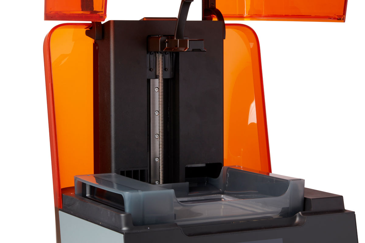 |
| Z-Achsen-Leitspindel | Die Z-Achsen-Leitspindel steuert die vertikale Bewegung des Konstruktionsplattformwagens. |  |
| Endschalterplatine | Eine einzelne Platine ist mit zwei optischen Sensoren verbunden, um zu erkennen, wann der Konstruktionsplattformschlitten die Oberseite des Turms erreicht und wann die Konstruktionsplattform installiert ist. |  |
| Heizelement | Das Harz im Harztank wird durch heiße Luft erwärmt, die aus dem Turm hinter dem Harztank geblasen wird. Die warme Luft in der Druckkammer erwärmt das Kunstharz und die Lufttemperatur wird durch einen Temperatursensor am Lufteinlass gemessen. |  |
| Lüfter | Ein Heizlüfter bläst Luft über das Heizelement in den Harztank. |  |
Plattform
| Artikel | Beschreibung | Abbildung |
|---|---|---|
| Konstruktionsplattform | Die Aluminium-Basis bietet eine Oberfläche, an der sich Drucke anhaften. |  |
| Plattformverriegelung | Dieser Hebel ist Teil des Verriegelungsmechanismus, der die Konstruktionsplattform sichert. |  |
| Konstruktionsplattformschlitten | Der Schlitten ist der Metallarm, auf den die Konstruktionsplattform geschoben wird. |  |
| Konstruktionsplattform-Sensor | Das Einsetzen der Konstruktionsplattform löst einen Endschalter in der Z-Achse aus. Der Drucker erkennt, wann die Konstruktionsplattform korrekt in ihrer Ausgangsposition installiert ist. | 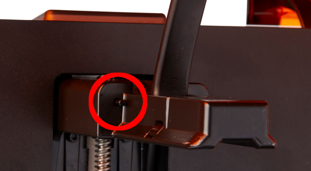 |
| Konstruktionsplattformverriegelungsfeder | Der Federmechanismus im Konstruktionsplattformschlitten ermöglicht es der Plattformverriegelung, sich nach oben und unten zu bewegen. Er verriegelt und entriegelt außerdem mechanisch die Konstruktionsplattform. |  |
| Gewindestifte der Plattformverriegelung | Mit diesen drei Schrauben wird die Spannung der Plattformverriegelung eingestellt. Kontaktieren Sie den Formlabs Kundenservice , bevor Sie diese Schrauben einstellen, da eine falsche Justierung zu Schäden am Gerät führen kann. |  |
Harztank
| Artikel | Beschreibung | Abbildung |
|---|---|---|
| Harztank | Der Harztank ist der Hauptbehälter für die Aufnahme von Harz, nachdem es aus der Kartusche abgegeben wurde. Das Kunstharz wird auf der Konstruktionsplattform ausgehärtet, wenn der Laser den Film auf der Unterseite des Tanks passiert. Verwenden Sie nur zugelassene Materialien und Verfahren zur Reinigung des Harztanks und des Films. |  |
| Tankgriffe | Kunststoffgriffe an jeder Seite des Harztanks ermöglichen das einfache Einsetzen, Herausnehmen und Tragen des Tanks. Vermeiden Sie es, den Boden des Harztanks zu berühren, da Fingerabdrücke Schlieren hinterlassen können, die den optischen Pfad blockieren. |  |
| Tankschnabel | Diese Ausbuchtung an der Rückseite des Harztanks befindet sich unterhalb der Abgabeöffnung der Kartusche und nimmt das Kunstharz aus der Kartusche auf. |  |
| Film | Ein langlebiger, zweischichtiger Film bildet die Bodenfläche des Harztanks. Die Teile werden in dem harzgefüllten Spalt zwischen dem Film und der Konstruktionsplattform gedruckt. Die Qualität der Druckteile hängt davon ab, ob der Film sauber und frei von Schäden und Ablagerungen ist. |  |
| ID-Chip des Harztanks | Der ID-Chip des Harztanks verwendet ein elektrisch löschbares, programmierbares Nur-Lese-Speicher (EEPROM). Die Tankfederkontakte lesen den Chip, um die einzigartige Tank-ID und den aktuellen Harztyp zu erfassen. |  |
| Mischer | Jeder Harztank ist mit einem Mischer ausgestattet. Der Mischer verbessert die Gleichmäßigkeit der Drucke, indem er den Konstruktionsbereich freihält und das Kunstharz zirkulieren lässt. Der Mischer ist mit einer Magnetkupplung am Rollenhalter befestigt und befindet sich bei Nichtgebrauch unter dem Mischergehäuse. Schaber auf der Ober- und Unterseite des Mischers halten jeweils die Konstruktionsplattform und den Film frei. |  |
| Mischergehäuse | Wenn der Mischer nicht in Gebrauch ist, ruht er in einem teilweise geschlossenen Fach auf der linken Seite des Harztanks. Der Schwimmer ist dauerhaft im Mischergehäuse befestigt. |  |
| Schwimmer | Ein Scharnier-Schwimmer ruht auf der Oberfläche des Harzes. Das Gegengewicht aus Aluminium bewegt sich vor der LevelSense-Platte. So kann die Harzmenge im Tank bestimmt werden. | 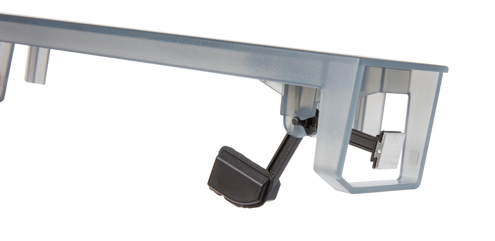 |
| Tankbehälter | Jeder Harztank wird mit einem Behälter mit Deckel geliefert, in dem der Harztank aufbewahrt werden kann, wenn er nicht in Gebrauch ist. Bei neueren Harztanks dient der Versandkarton auch als Tankgehäuse. |  |
| Tankwerkzeug | Zur Inspektion und Reinigung des Inneren des Harztanks ist ein spezieller zweiteiliger Spachtel erforderlich. Dies ist das einzige Werkzeug, mit dem die innere Filmoberfläche gereinigt werden darf. |  |
Tankträger
| Artikel | Beschreibung | Abbildung |
|---|---|---|
| Tankträger | Diese Baugruppe hält den Harztank und spannt den Film. Der Tankträger wird von der Oberschale bedenkt und enthält den Filmspanner, den LevelSense, die Tankfederkontakte, die Tankaufnahme-Biegeelemente und die Verriegelungssensoren. |  |
| Tankträgerführungen | Die Seitenwände des Harztanks sind mit linearen Schlitzen an jeder Seite des Tankträgers verbunden. Während des Drucks spannen die Schienen die Tankwände und den Film auf. |  |
| Filmspannvorrichtung | Ein Motor zieht an den Tankseitenwänden nach außen, um eine straffe Filmoberfläche im Harztank zu erzeugen. |  |
| Tankfedern | Diese elektrischen Kontakte auf der Rückseite des Harztankträgers lesen den EEPROM-ID-Chip des Harztanks aus, um die Anwesenheit des Tanks zu erkennen und den Harztyp an PreForm zu übermitteln. |  |
Hauptplatine
| Artikel | Beschreibung | Abbildung |
|---|---|---|
| Hauptplatine | Die Hauptplatine ist die Hauptschaltung, über die alle Systeme im Drucker kommunizieren. |  |
| Stromversorgung | Der Form 3/Form 3B verwendet eine Stromversorgung mit 100–240 V. Das interne Netzteil wandelt die Netzspannung in eine Gleichspannung von +24 V um. |  |
| Anschluss für die Frontanzeige | Dieser Anschluss verbindet das Display über ein Flachbandkabel mit der Hauptplatine. |  |
| WLAN-Antenne | Die WLAN-Antenne ermöglicht die drahtlose Verbindung des Form 3/Form 3B. Die Antenne ist mit der Hauptplatine des Druckers verbunden. |  |
| Ethernet-Anschluss | Der Form 3/Form 3B kann über Ethernet mit einem Netzwerk verbunden werden. Der Anschluss ist mit der Hauptplatine verbunden und ist von der Rückseite des Geräts zugänglich. |  |
| USB-Anschluss | Der Form 3/Form 3B kann über USB mit einem Computer verbunden werden. Der Anschluss ist mit der Hauptplatine verbunden und ist von der Rückseite des Geräts zugänglich. |  |
| Lüfter | Kühlgebläse saugen warme Luft von den elektronischen Komponenten weg. |  |
LevelSense
| Artikel | Beschreibung | Abbildung |
|---|---|---|
| LevelSense-Platte | Zwei Induktionsspulen bestimmen die Harzmenge im Tank, indem sie die relative Höhe des Schwimmers erfassen. |  |
Optik
| Artikel | Beschreibung | Abbildung |
|---|---|---|
| Light Processing Unit (LPU) | Diese austauschbare Baugruppe enthält den Laser und die Spiegel, die den Weg des Lasers steuern und so für einen sauberen, klaren Laserpunkt sorgen. Die LPU ist auf der rechten Seite des LPU-Gehäuses befestigt. |  |
| Laser | Der Laser ist die Quelle der Aushärteenergie im Form 3/Form 3B. Er verfügt über eine violette 405-nm-Diode mit einer maximalen Leistung von 250 mW. Der Form3/Form 3B ist ein Laserprodukt der Klasse 1. |  |
| Kabel der Light Processing Unit (LPU) | Ein flaches, flexibles Kabel verbindet die LPU mit der Hauptplatine. |  |
| Gehäuse der Light Processing Unit (LPU) | Das Aluminiumgehäuse für die optische Einheit bewegt sich nach links und rechts entlang der X-Achsen-Leitspindel. Die LPU, der Rollenhalter und der Mischer werden alle in dem LPU-Gehäuse gesteuert. |  |
| Rollenhalter | Segmentierte Metallstangen (Rollen) dienen als Gleitfläche für die reibungslose Bewegung des LPU-Gehäuses über den Film im Harztank. Die Rollen umgeben das optische Fenster. Saubere Rollen schützen den Film und erhalten die Druckqualität. |  |
| Optisches Fenster | Das optische Fenster befindet sich im Rollenhalter und ist eine Glasplatte mit einer Antireflexbeschichtung. Es schützt die empfindlichen Spiegel im Innern der LPU vor Staub und anderen Verunreinigungen. Halten Sie das optische Fenster sauber, um Fehldrucke zu vermeiden. | 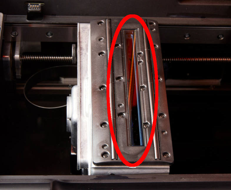 |
| X-Achsen-Leitspindel | Die X-Achsen-Leitspindel steuert die horizontale Bewegung des LPU-Gehäuses. |  |