Required Supplies:
Formlabs:
- Replacement motherboard (RP-CU2L-MOBO-01)
- 2 mm hex driver (included in the Form 4L tool cap assembly)
Third-party:
- Phillips driver
- Nitrile gloves
- Anti-static grounding strap


The Form Cure L V2 motherboard is mounted to the back of the machine’s display assembly. If the motherboard is faulty or malfunctioning, the Form Cure L V2 may behave erratically or not function at all.
Use this guide to replace the motherboard on a Form Cure L V2.
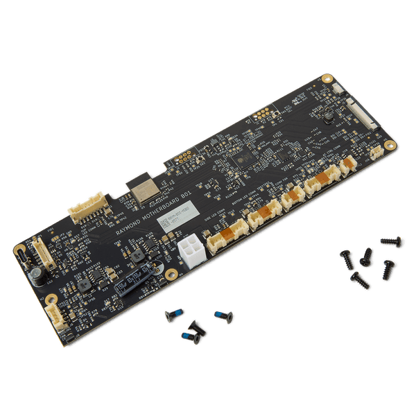
Required Supplies:
Formlabs:
Third-party:
Geschätzte Dauer: 15–20 Minuten
Gefahr:
Lesen und befolgen Sie alle Sicherheitsanweisungen und Warnungen im Benutzerhandbuch. Ein Ersatz unter Verwendung inkorrekter Teile führt zu Verbrennungen, Stromschlägen, Feuer oder Explosionen. Entsorgen Sie alle Teile gemäß den örtlichen Vorschriften.
Vorbereitung des Arbeitsbereichs
Overview: Prepare the Form Cure L V2 and workspace for replacing the motherboard.
Step 1: Prepare the workspace
Clear a workspace around your machine. Ensure that the workspace is well-ventilated and free of dust.
Step 2: Unplug the machine
Turn off the machine using the power switch on the back of the unit. Disconnect the power cable before continuing with maintenance. Do not perform maintenance on the machine while it is connected to power. Wait five minutes after disconnecting the machine from power before proceeding. If the machine was recently in use, the post-cure chamber will be warm. Wait at least 10 minutes for the chamber to cool.
Gefahr:
Die Durchführung von Wartungsarbeiten an einem angeschlossenen Gerät erhöht das Risiko eines Stromschlags. Entfernen Sie niemals das Gehäuse des Geräts, wenn es mit der Stromversorgung verbunden ist. Schließen Sie das Gerät niemals wieder an die Stromversorgung an, solange das Gehäuse nicht wieder montiert ist.
Entfernen der Hauptplatine
Overview: Disconnect and remove the original motherboard.
Schritt 1: Tür öffnen
Öffnen Sie die Tür der Aushärtekammer, um an die Schrauben zu gelangen, mit denen die Frontplatte befestigt ist.
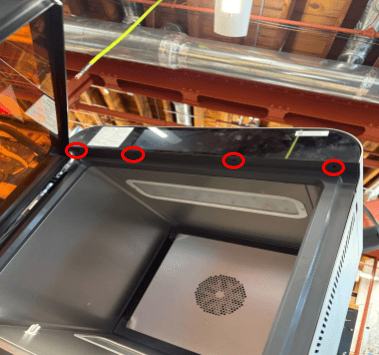
Schritt 2: Schrauben der Hauptplatine und der Displaybaugruppe entfernen
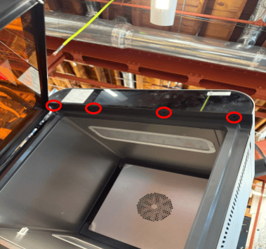
Lösen und entfernen Sie mit einem 2-mm-Innensechskantschlüssel die vier Schrauben, mit denen die Hauptplatine und die Displaybaugruppe am Rahmen des Geräts befestigt sind. Legen Sie die Schrauben beiseite.
Schritt 3: Hauptplatine und Displaybaugruppe demontieren
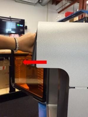
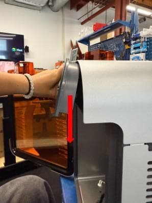
Kippen Sie die Hauptplatine und die Displaybaugruppe vorsichtig nach oben und ziehen Sie sie dann nach unten. Die Baugruppe sollte sich vom Rahmen des Geräts lösen. Ziehen Sie nicht ruckartig an der Hauptplatine und der Displaybaugruppe, da diese noch über ein Kabelset mit dem Form Cure L V2 verbunden sind.
Schritt 4: Die Kabel der Hauptplatine abziehen
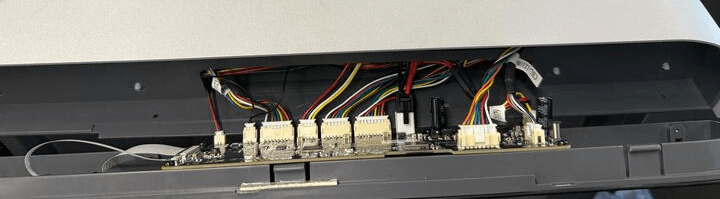
Disconnect all of the cables from the motherboard except for the two ribbon cables. For each, squeeze the tab and slide the cable out of the connector. Take care not to pull on the wires themselves.
Fully separate the motherboard and display assembly from the machine and set it display-side down on your work surface.
Step 5: Uninstall the motherboard
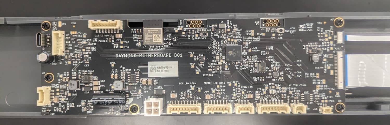
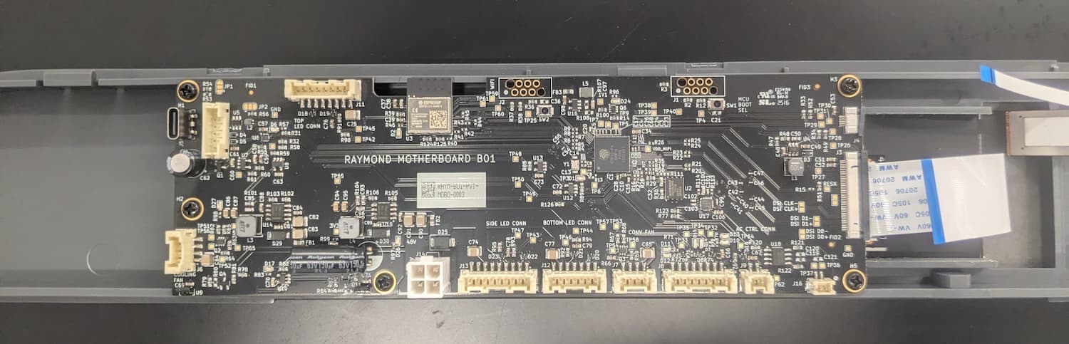
Disconnect the two ribbon cables from the side of the motherboard. For both, slide the black latch on the cable connector away from the white connector body. Once the latch is open, the ribbon cable should separate from the connector with minimal force. Take care not to fold or otherwise damage the ribbon cables.
Using a Phillips driver, loosen and remove the five screws securing the motherboard to the display assembly. Set the screws aside.
Fully separate the motherboard from the display assembly and set it aside for disposal with electronic waste.
Ersetzen der Hauptplatine
Overview: Connect, mount, and secure the new motherboard.
Step 1: Mount and secure the motherboard
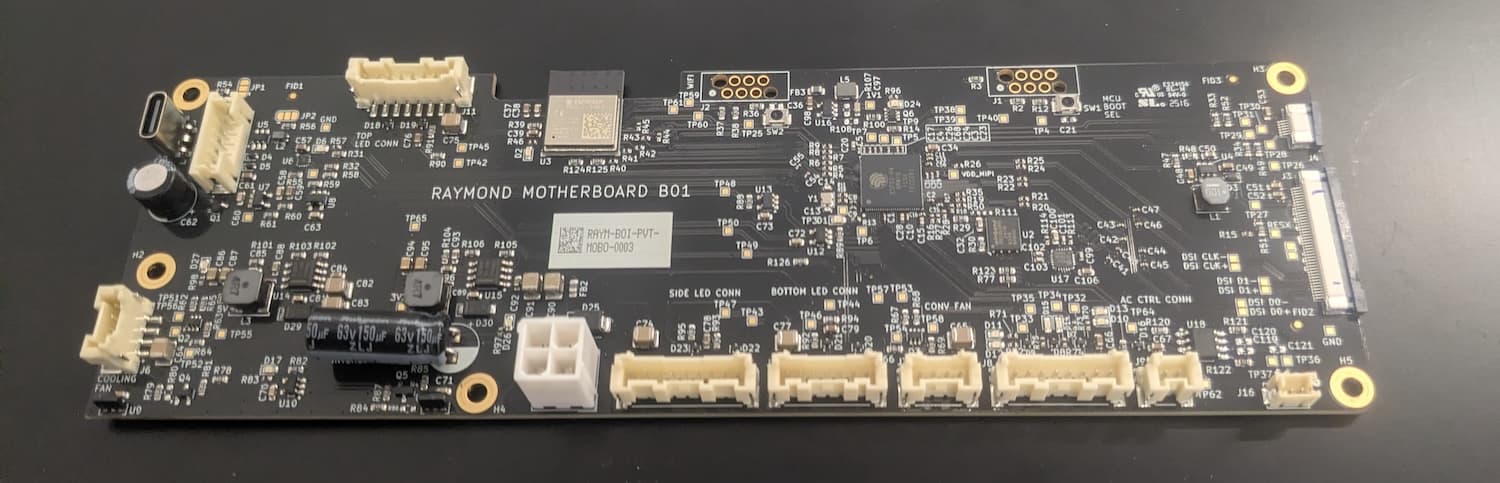
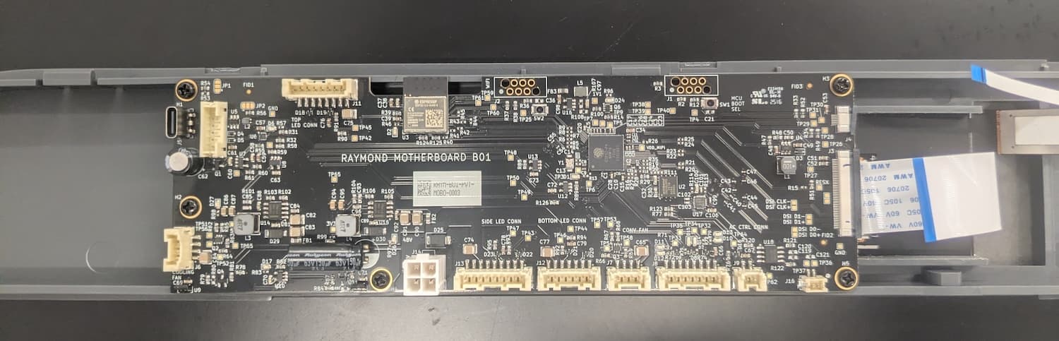
Remove the replacement motherboard from its packaging and place it on the back of the display assembly, aligning the five screw holes in the motherboard with the corresponding screw holes in the display. Thread one motherboard mounting screw into each of the five screw holes, then use a Phillips driver to tighten until snug.
Step 2: Connect the ribbon cables to the motherboard
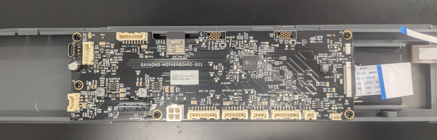
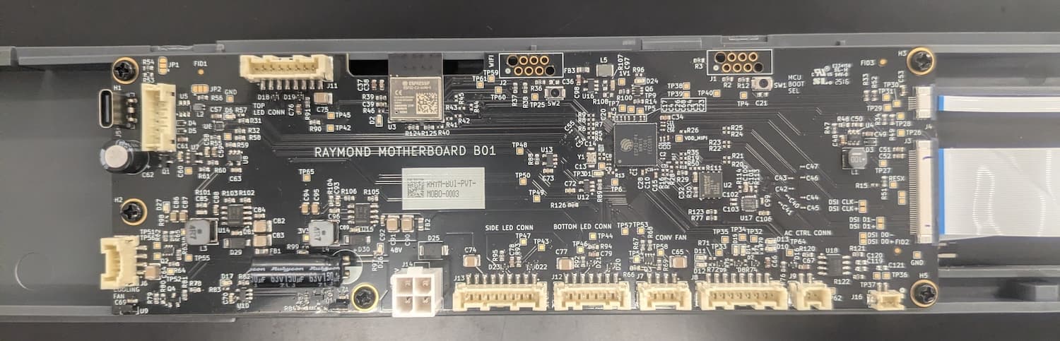
Carefully slide the two ribbon cables into their respective connectors on the motherboard. Push the black latches towards the white connector body. When the latch is flush with the connector body, the ribbon cable is secure.
Step 3: Connect the remaining motherboard cables
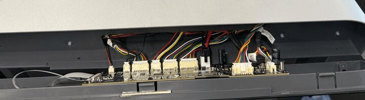
Hold the motherboard and display assembly in front of the machine, near its mounting point. Reconnect all cables to the motherboard, using the image here as a reference. Each cable only fits into its connector in the correct orientation. The locking tab clicks into place when the cable is fully connected.
Step 4: Mount the motherboard and display assembly
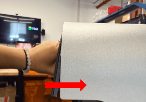
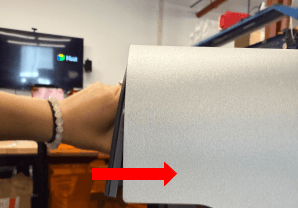
Kippen Sie die Hauptplatine und die Displaybaugruppe leicht nach oben. Führen Sie ihn unter die vordere Kante des Obergehäuses und kippen Sie dann die Unterseite der Baugruppe in Position. Vergewissern Sie sich, dass sie bündig mit dem Gehäuse des Geräts abschließt und dass die vier Schraubenlöcher in der Unterseite der Hauptplatine und der Displaybaugruppe mit den entsprechenden Löchern in der Form Cure L V2 übereinstimmen.
Thread one mounting screw into each of the four screw holes in the bottom of the motherboard and display assembly. Using a 2 mm hex driver, tighten the screws until snug.
Abschließen der Reparatur
Overview: After installing the new motherboard, perform final checks.
Step 1: Power on the machine
Connect the power cable to the machine and its power supply. Turn on the switch at the back of the machine. Start a post-cure cycle and check that the machine operates normally.