Erforderliches Zubehör:
Formlabs:
- Ersatz-LED-Platine für Fuse Sift, bis zu 2x
Drittanbieter:
- 2,5-mm-Innensechskantschlüssel (flaches Ende)
- Loctite 243 oder gleichwertige Schraubensicherung
- Antistatisches Armband


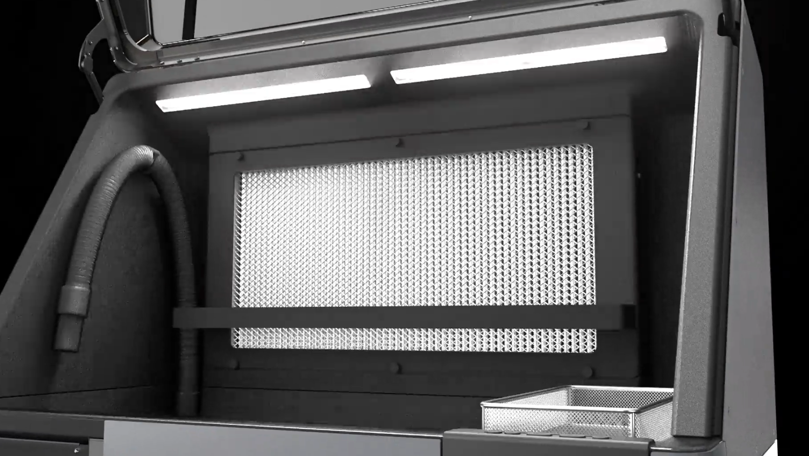
Der Fuse Sift verwendet zwei LED-Bänke, um den Arbeitsbereich während des Gebrauchs zu beleuchten. Wenn eines oder beide dieser LED-Module defekt sind oder nicht richtig funktionieren, ist es schwieriger, Ihre Druckteile während der Nachbearbeitung zu sehen.
Verwenden Sie diesen Leitfaden, um die Arbeitsbereichsbeleuchtung des Fuse Sift zu ersetzen.
Erforderliches Zubehör:
Formlabs:
Drittanbieter:
Geschätzte Zeit: 15–20 Minuten
Vorbereitung des Arbeitsbereichs
Überblick: Bereiten Sie den Fuse Sift und Ihren Arbeitsbereich auf den Austausch der Arbeitsbereichsbeleuchtung vor.
Schritt 1: Arbeitsbereich vorbereiten
Um die Arbeitsbereichsbeleuchtung zu ersetzen, müssen Sie auf die Rückseite und die Oberseite des Fuse Sift zugreifen. Schaffen Sie genügend Platz um das Gerät herum, um dies sicher zu tun.
Schritt 2: Den Fuse Sift ausstecken
Schalten Sie den Fuse Sift aus und ziehen Sie das Netzkabel von der Rückwand ab.
Gefahr:
Wenn Sie dieses Verfahren am Fuse Sift durchführen, während er eingesteckt ist, erhöht sich das Risiko eines Stromschlags. Warten Sie nach dem Trennen der Stromversorgung des Fuse Sift mindestens fünf Minuten, bevor Sie Wartungsarbeiten durchführen.
Abnehmen des oberen Gehäusepaneels
Überblick: Demontieren Sie das obere Gehäusepaneel, um an die Arbeitsbereichsbeleuchtung zu gelangen.
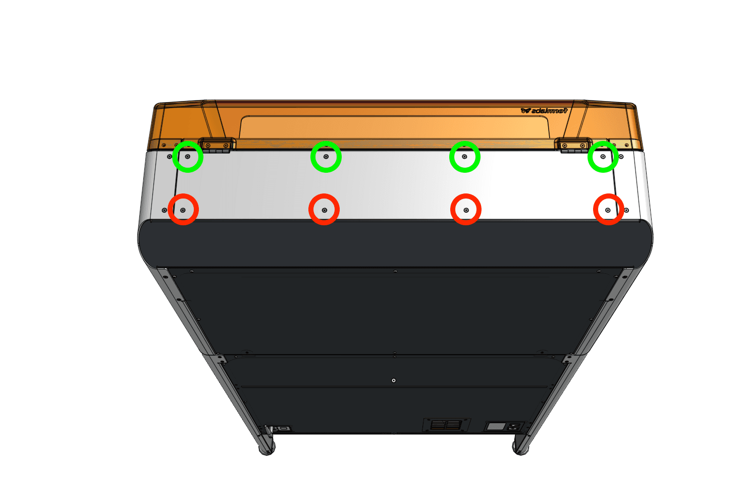
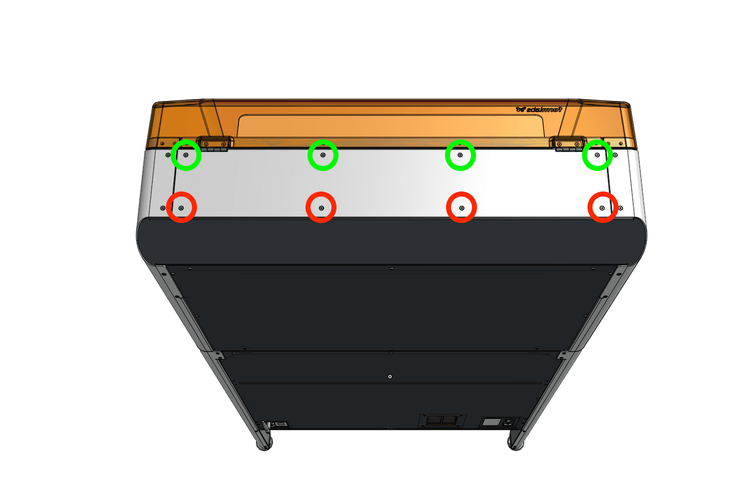
Lösen und entfernen Sie mit einem 2,5-mm-Innensechskantschlüssel die acht Senkschrauben, mit denen das obere Gehäusepaneel am Fuse Sift befestigt ist. Die vier Schrauben, die näher an der Haube liegen, sind 10,0 mm lang, während die vier Schrauben, die näher an der Rückseite des Fuse Sift liegen, 8,0 mm lang sind. Legen Sie die Schrauben beiseite.
Halten Sie das Paneel fest, damit es nicht herunterfällt, wenn Sie die letzte Schraube entfernen.
Heben Sie das obere Gehäusepaneel vom Fuse Sift ab und legen Sie es beiseite.
Entfernen der LED-Platte(n)
Überblick: Bauen Sie eine oder beide LED-Platinen aus, die den Arbeitsbereich des Fuse Sift beleuchten.
Schritt 1: Die Kabel der Arbeitsbereichsbeleuchtung abklemmen
Falls noch nicht geschehen, legen Sie ein antistatisches Armband an und verbinden Sie es mit einem bekannten Erdungspunkt. Befestigen Sie das Armband nicht an pulverbeschichteten oder lackierten Oberflächen.
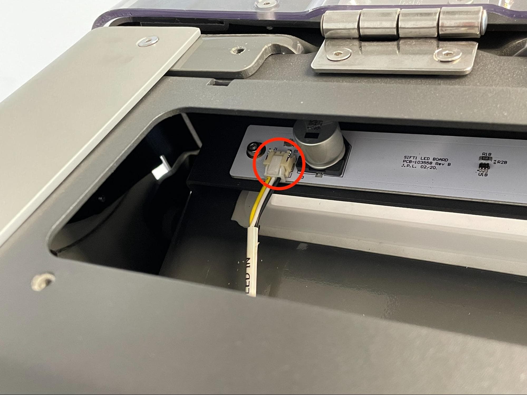
Left-hand board: LED IN
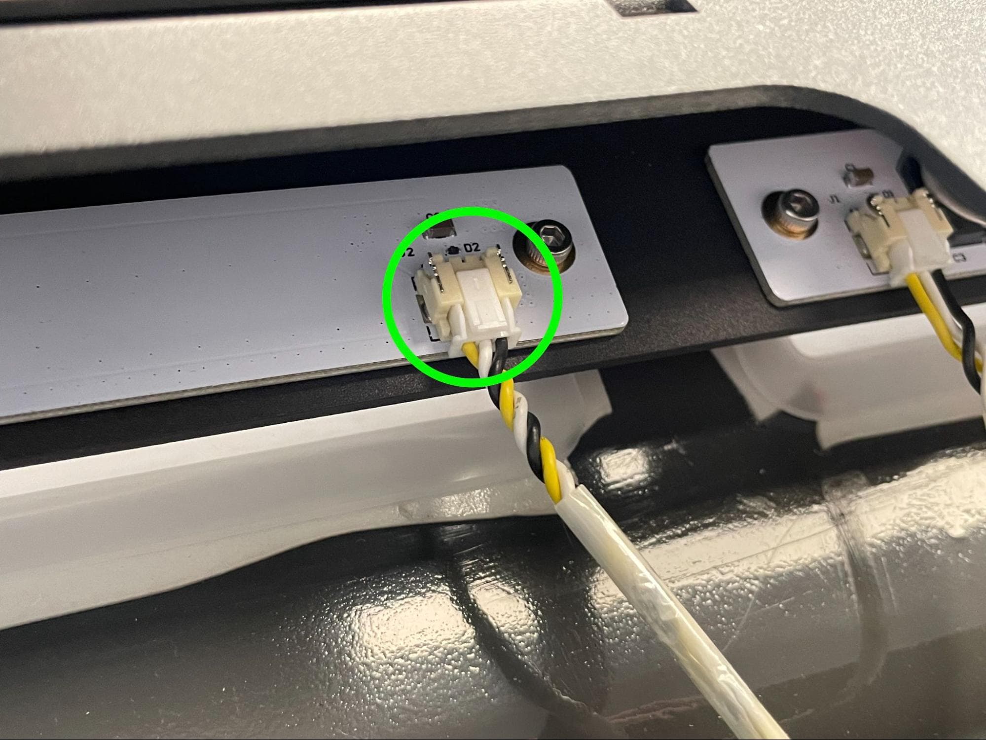
Left-hand board: LED OUT
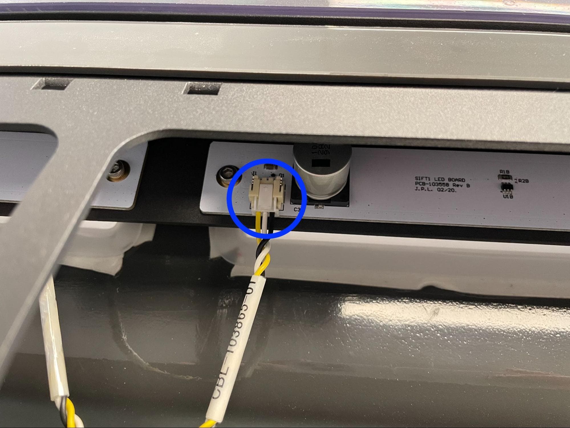
Right-hand board: CBL-103865-01
Disconnect the cables from the LED board or boards you are replacing. When looking from the back of the machine:
Step 2: Unscrew the workspace light mounting screws
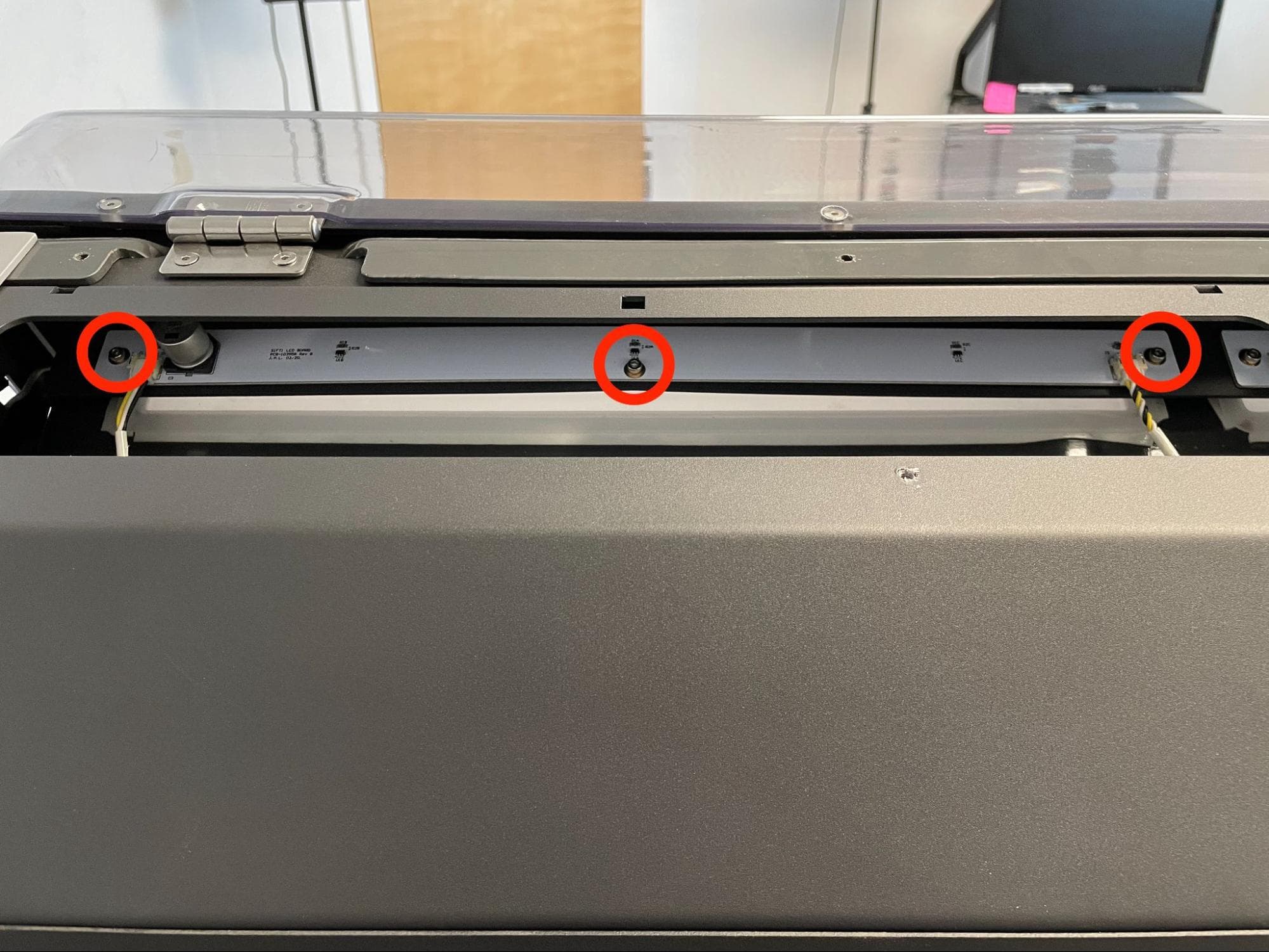
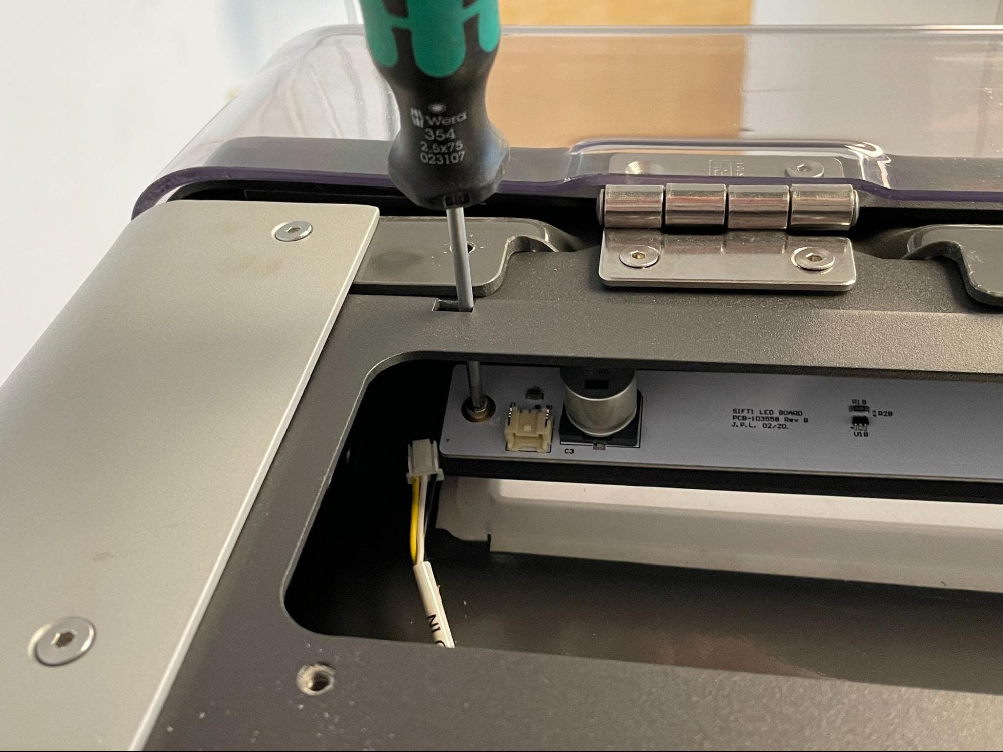
Using a 2.5 mm hex driver loosen and remove the three 10.0 mm M4 cap screws securing the LED board you are replacing the Fuse Sift. Insert the driver through the access port above each cap screw. Do not use an Allen key, as it may fall into the back of the machine. Set the screws aside. If you are replacing both sets of LEDs, repeat for the other board.
Step 3: Remove the LED board
Remove the LED board from the Fuse Sift and set it aside for disposal with electronic waste. If you are replacing both sets of LEDs, repeat for the other board.
Installing the replacement LED board(s)
Overview: Mount, secure, and connect the replacement LED board(s).
Step 1: Mount the new LED board
Position the new LED board with the large round capacitor on the left. Place it on its mounting surface in the Fuse Sift, aligning the three screw holes in the board with the corresponding holes in the Fuse Sift. If you are replacing both sets of LEDs, repeat for the other board.
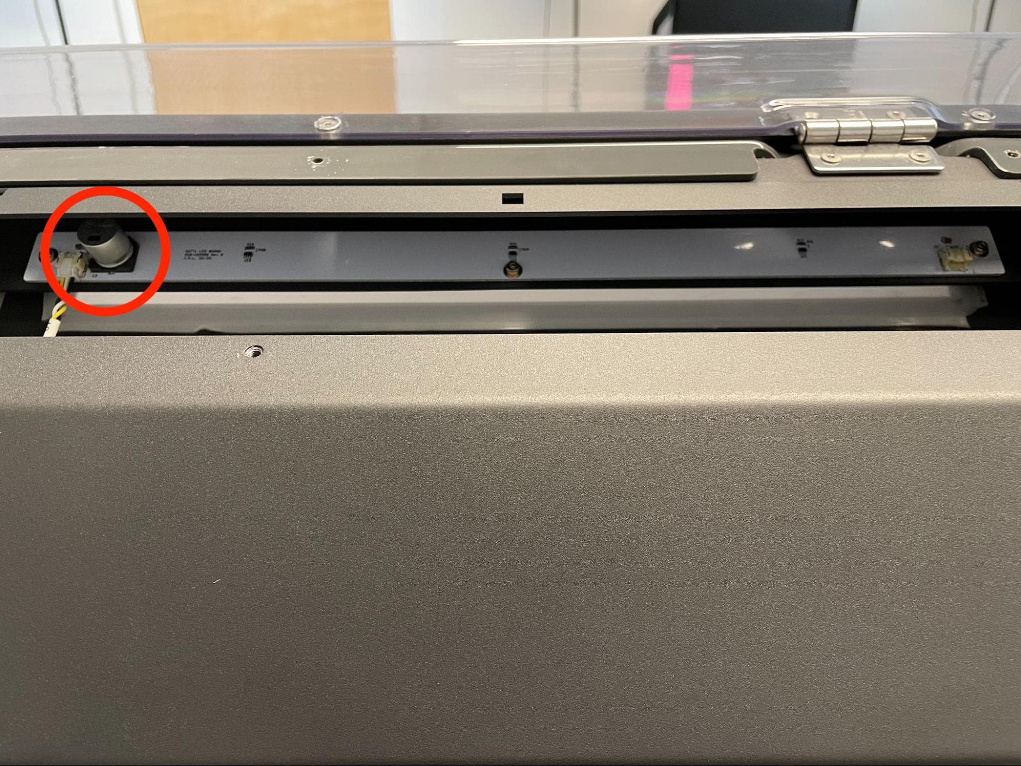
Step 2: Secure the LED board
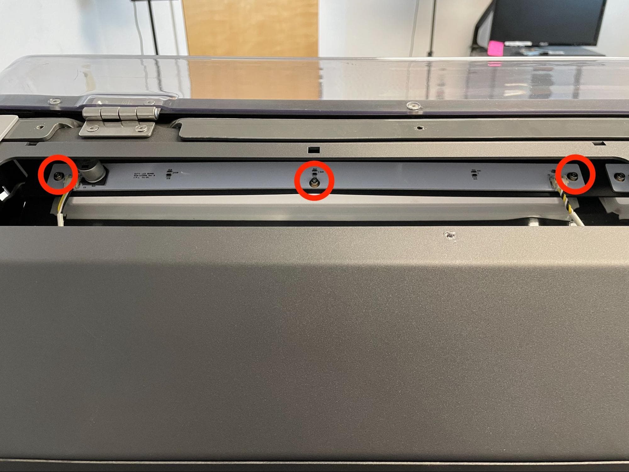
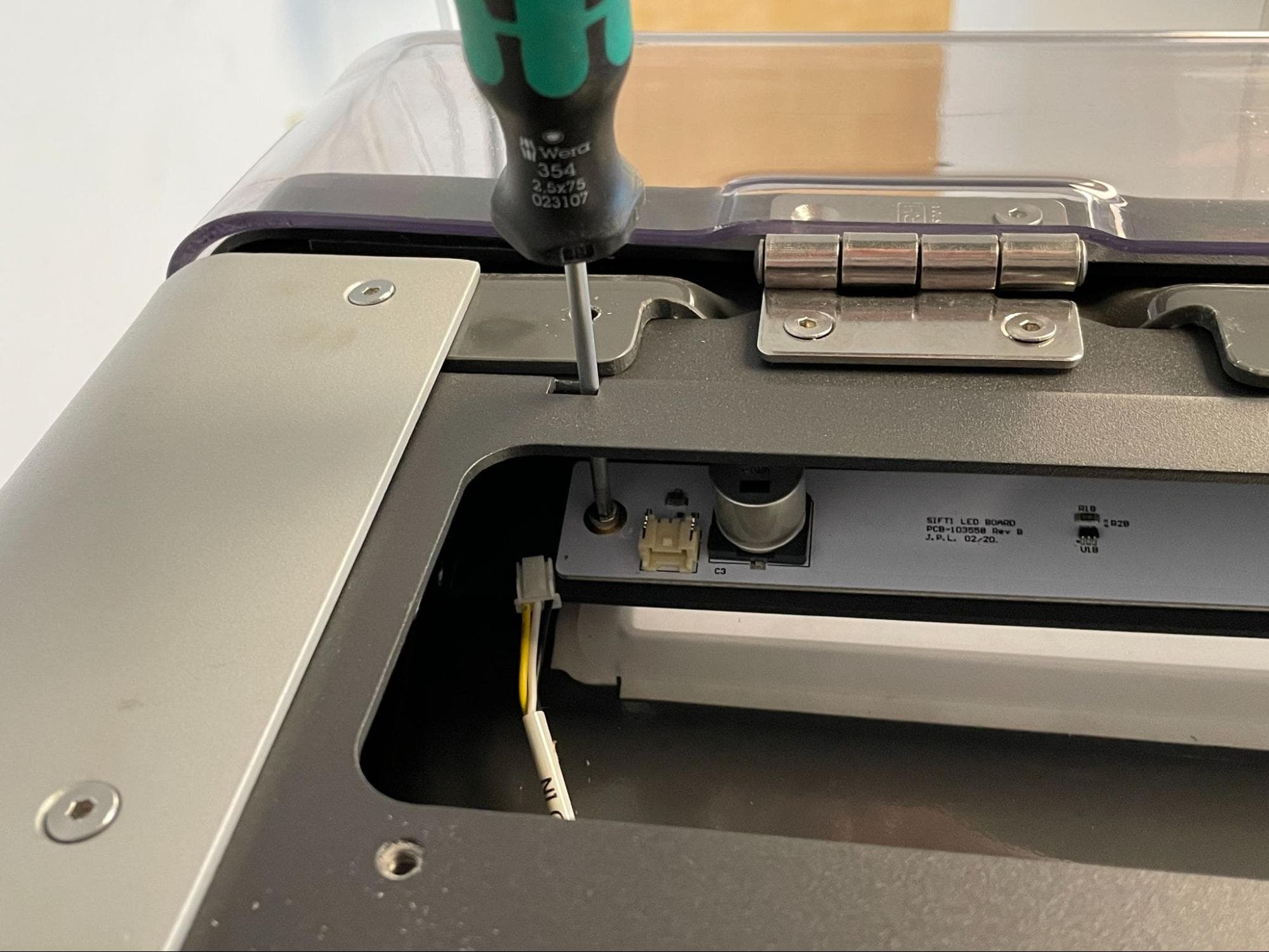
Apply a small dab of Loctite 243 or equivalent threadlocker to each LED board mounting screw. Thread one 10.0 mm M3 cap screw into the three screw holes in the LED board. Insert a 2.5 mm hex driver through the access port above each screw and tighten until snug. If you are replacing both sets of LEDs, repeat for the other board.
Step 3: Connect the workspace light cables
Left-hand board: LED IN
Left-hand board: LED OUT
Right-hand board: CBL-103865-01
Connect the cables to the new LED board(s). When looking from the back of the machine:
Reinstalling the top enclosure panel
Overview: After replacing the workspace lights, mount and secure the top enclosure panel.
Place the top enclosure panel on top of the Fuse Sift, aligning the eight screw holes in the panel with the corresponding screw holes in the Fuse Sift.
Apply a small dab of Loctite 243 or equivalent threadlocker to the eight top enclosure panel mounting screws. Thread one 8.0 mm screw into the four screw holes closer to the rear of the machine. Thread one 10.0 mm screw into the four screw holes closer to the hood. Using a 2.5 mm hex driver, tighten until snug.
Finalizing the repair
Overview: After installing the new workspace lights, test the repair.
Step 1: Power on the Fuse Sift
Reconnect the Fuse Sift to its power source. Flip the power switch to the ON position.
Step 2: Check the workspace lights
Turn on the workspace lights using the control panel or touchscreen. Check that both sets of LEDs turn on. Contact Formlabs Support or your certified service provider to share the results of the procedure.