WHITE PAPER
Formlabs Logo

Dimpling and pitting (SLS)

Dimpling and pitting (SLS)

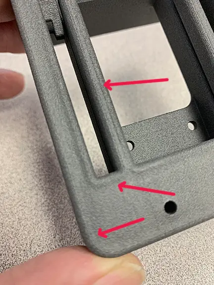
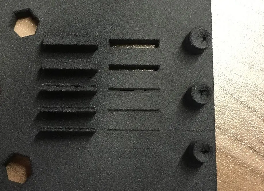
During a print, the middle of a part is hotter than its edges. The edges cool and contract faster than the middle does, causing the middle to shrink inwards. As a result, the upward-facing surfaces on printed parts may sink due to uneven cooling. Mild cases can look as if the top surface of a part has caved in slightly and are known as "dimpling." In more severe cases, known as "pitting," a puncture several layers deep can form in the part.

This issue is most common when printing with Nylon 12 on Fuse 1+ 30W printers, but may occur with any material on a Fuse 1 generation device. Due to print process differences, dimpling and pitting tends to be more noticeable with Fuse 1+ 30W units.

Dimpling on a printed part.
Pitting on a printed part.

Symptoms

  • Impressions in the top surface of the part
  • Holes that are several layers thick but do not pass completely through the part

Causes

  • Clouded IR sensor
  • Certain part geometries or orientations that lead to uneven cooling
  • Print bed temperature is too high

Troubleshooting steps

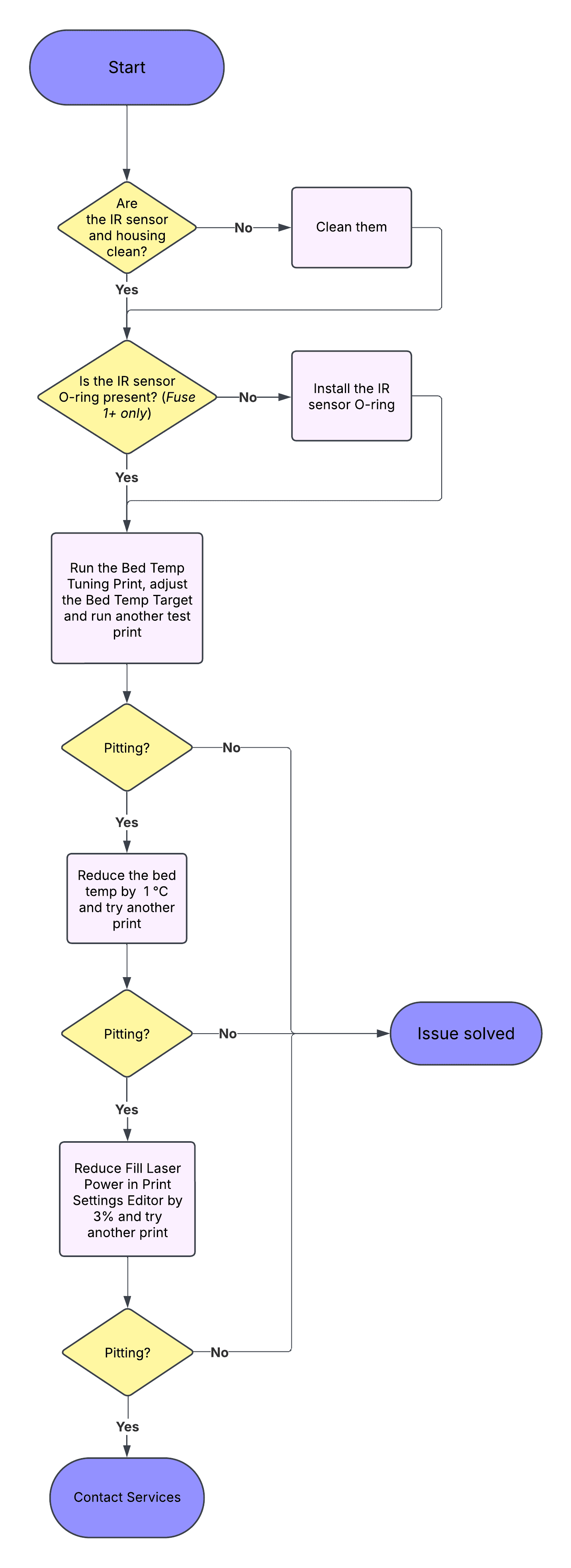
Troubleshooting flowchart for dimpling and pitting

Step 1: Inspect the IR sensor

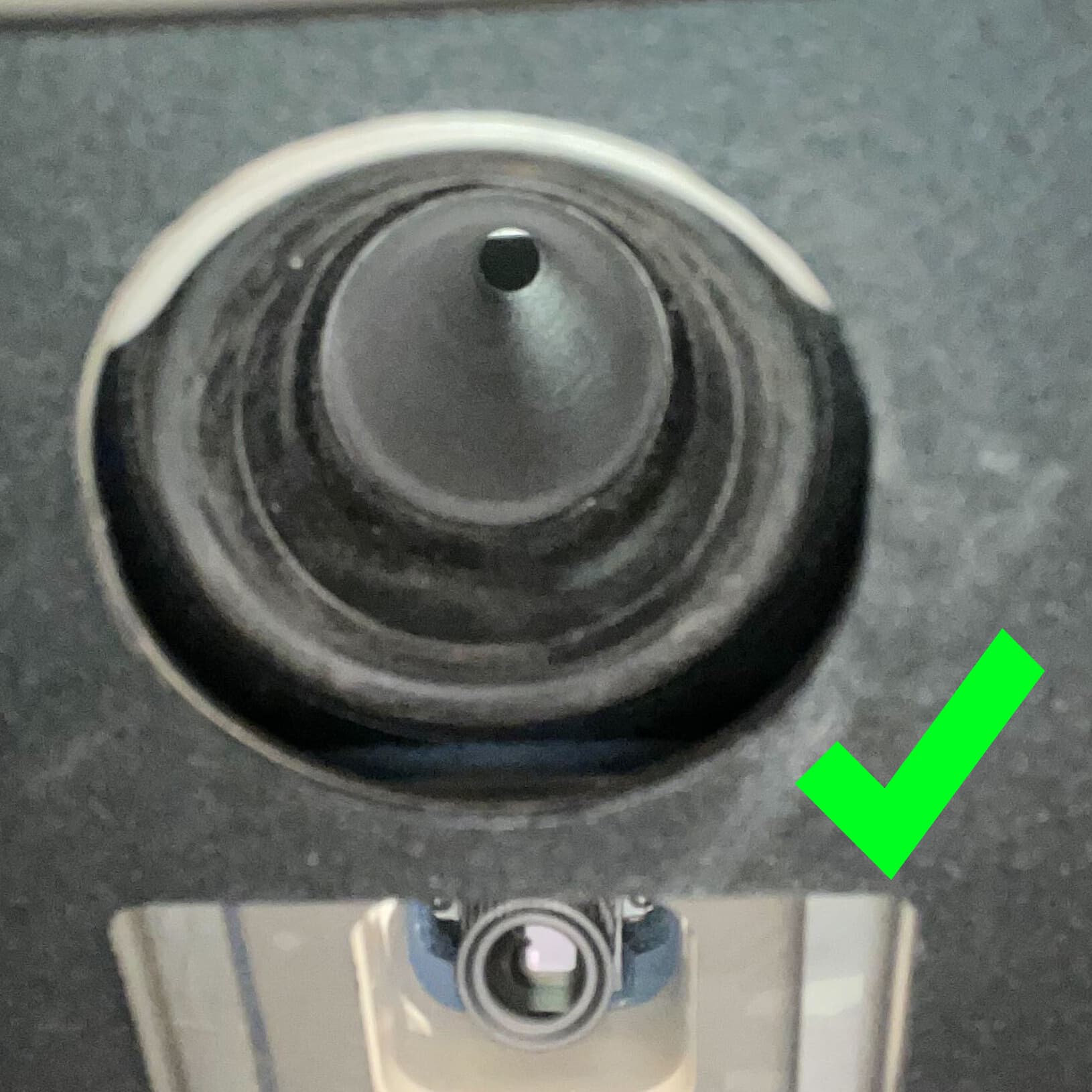
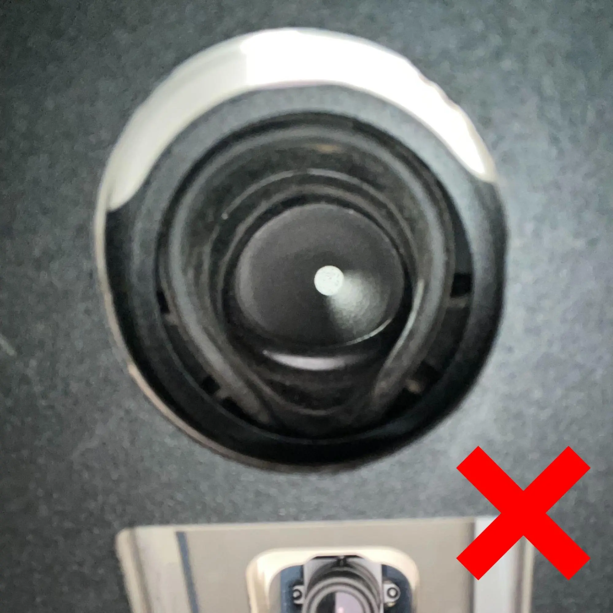
The sintering process creates byproducts, including a white powder called laurolactam. These byproducts accumulate inside the print enclosure, filters, exhaust line, and optical surfaces. Laurolactam buildup on the IR sensor may lead to overheated print beds, causing print defects like dimpling and pitting. Inspect the infrared sensor and infrared sensor housing for any laurolactam that has built up in the sensor’s field of view.

After cleaning, ensure that the rubber lower portion of the IR sensor housing is flush with the upper portion of the housing as shown. If the two portions of the IR sensor housing are not flush with one another, contact Formlabs Support or a certified service provider for further instruction.

alttext
alttext

Step 2: Check for the IR sensor O-ring (Fuse 1+ 30W only)

The Fuse 1+ 30W uses an O-ring around the IR sensor shaft to improve print enclosure sealing. This prevents IR sensor contamination and reduces the likelihood of a print failure. Depending on the date of manufacture of your printer, this O-ring may come preinstalled or may be included with the printer packaging. If your printer came with a separately packaged O-ring, install the O-ring.

Wipe surfaces of the IR sensor with ethanol if there is any residue. Ensure that the IR sensor sits flat and is correctly installed on the printer.

Step 3: Reorient or relocate the model in PreForm

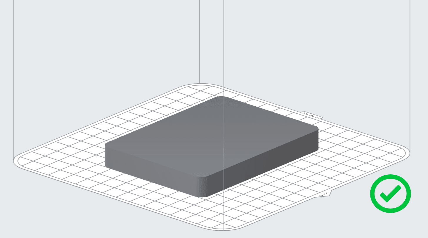
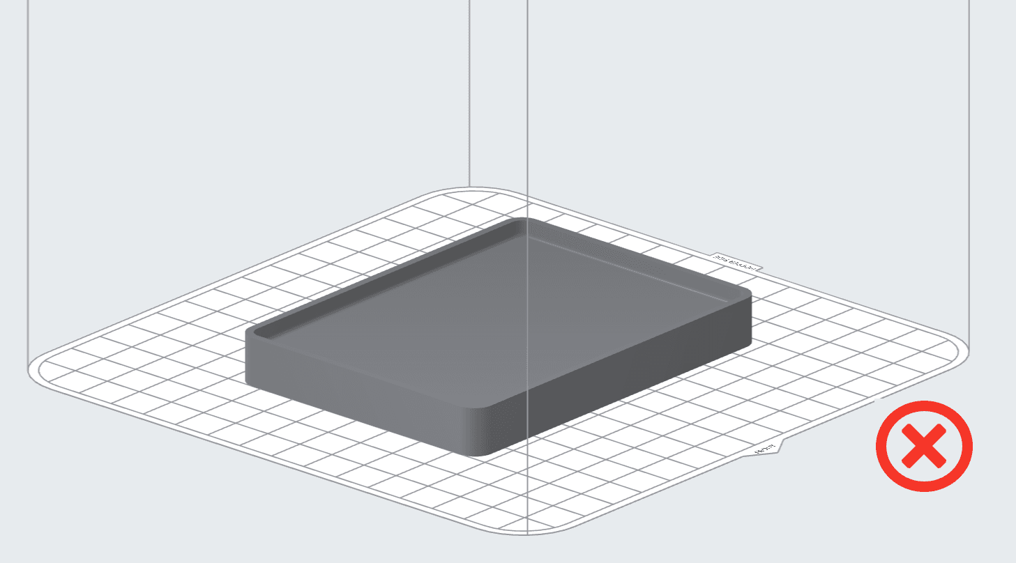
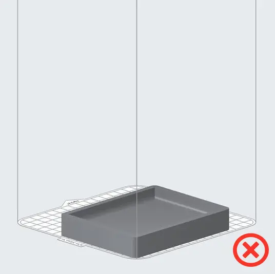
Dimpling and pitting only affect the top layer of printed parts. Thin geometries printed perpendicular to the Z-axis are especially prone to pitting. Orient these parts facing downward.

Model oriented downwards correctly in PreForm.
Model oriented upwards in PreForm.

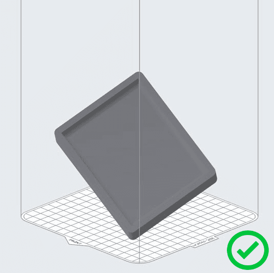
Depending on the part geometry, it may be best to orient parts at an angle so that the thinnest cross sections are not facing upward.

Model oriented at an angle in PreForm.
Model oriented upwards in PreForm.

Location in the build volume also contributes to dimpling. Parts placed towards the bottom of the build chamber for long prints are more likely to show dimpling than parts placed near the top.

Step 4: Tune the printer’s Bed Temperature Target

If dimpling or pitting persists, tune the printer’s bed temperature. Tune the Bed Temperature Target. Adjust the bed temperature, run a test print, and inspect the parts for defects. If dimpling or pitting persists, move to the next step.

Step 5: Reduce the printer’s Fill Laser Power (Fuse 1+ 30W printers printing with Nylon 12 only)

If adjusting the Bed Temperature does not mitigate the dimpling to an acceptable level, reduce the printer’s Fill Laser Power in 3% increments using the PreForm Print Settings Editor.

  1. Follow the steps in the article Using the PreForm Print Settings Editor (SLS) to create a custom print setting. Base the custom print setting on the Formlabs setting you are using for test prints.
  2. Locate the Fill Laser Power parameter and decrease it by 3% from the default value.

    For example, the Formlabs Speed Optimized v5.1 Print Setting for Nylon 12 at 110 microns has a default Fill Laser Power of 30000 mW. 3% of that value is 900 mW, so the power for this custom setting is 29100 mW.


alttext
  1. Print a test print using the custom print setting.
  2. If dimpling or pitting persists, continue to reduce Fill Laser Power in 3% increments, inspecting the parts after each test print. Repeat until you have reduced the parameter by a total of 9%.

Notice:

Reducing the Fill Laser Power can increase the chances of print defects. If an adjustment of -9% Fill Laser Power coupled with a -2 °C Bed Temperature Offset does not mitigate the dimpling to an acceptable level, contact Formlabs Support or a certified service provider .

Step 6: Contact Formlabs Support

If dimpling or pitting persists after following the troubleshooting steps above, contact Formlabs Support or a certified service provider and upload diagnostic logs.