
Required Supplies:
Formlabs:
- Cartridge floor
Third-party:
- 3 mm hex driver
- 2 mm hex driver
- T10 Torx driver
- Phillips head driver
- Nitrile gloves
- Paper towels
- Scissors

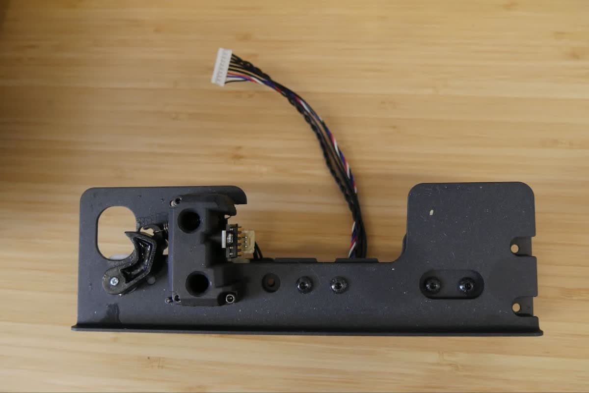
The resin cartridge sits on the cartridge floor, which contains a resin cartridge spring and dispense arm for dispensing resin. If the cartridge floor is malfunctioning or broken, the printer may fail to dispense resin properly or be prone to resin spills.
Use this guide to replace the Form 3 cartridge floor.
Required Supplies:
Formlabs:
Third-party:
Estimated time: 30 minutes
Preparing the workspace
Overview: Prepare the Form 3 and a dust-free workspace for replacing the cartridge floor.
Step 1: Remove the build platform
Remove the build platform first to avoid dripping resin into the printer cavity.
Step 2: Remove the resin cartridge
Remove the resin cartridge and close the vent cap to prevent resin from dripping off of the bite valve and into the printer.
Step 3: Remove and store the resin tank
Remove the resin tank, place it in the resin tank case, and cover it with its lid. Set the case and tank aside on a clean, flat surface.
Notice:
Wear gloves and hold the resin tank by the tank grips on either side to avoid contamination or damage to the underside of the tank.
Step 4: Prepare the workspace
Clear a workspace around your printer. Ensure that the workspace is well-ventilated and free of dust.
Step 5: Unplug the printer
Disconnect the power cable from the printer before continuing with maintenance. Do not perform maintenance on the printer while it is connected to power. Wait five minutes after disconnecting the printer from power before proceeding.
Danger:
Performing maintenance on the printer while it is plugged in increases the risk of electric shock. Never remove the back panel of the printer while the printer is plugged in. Never reconnect the printer to power while the back panel is uninstalled.
Removing the rear shell
Overview: Remove the rear shell of the printer to gain access to the resin cartridge floor.
Notice:
The Form 3 contains sensitive electronic components. Ground yourself before touching any electronics in the printer by using a grounding strap or touching a grounded piece of metal.
Step 1: Remove the rear shell screws (internal)
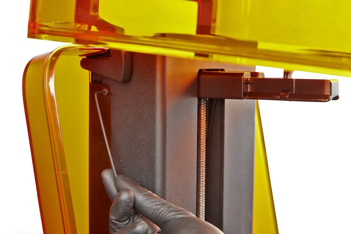
Open the printer cover. There is one screw on each side of the Z-tower. Depending on the age of your printer, they may be 2 mm hex screws or T10 Torx screws. Use the appropriate driver to loosen and remove the two screws on the side of the Z-tower.
Step 2: Remove the rear shell screws (external)
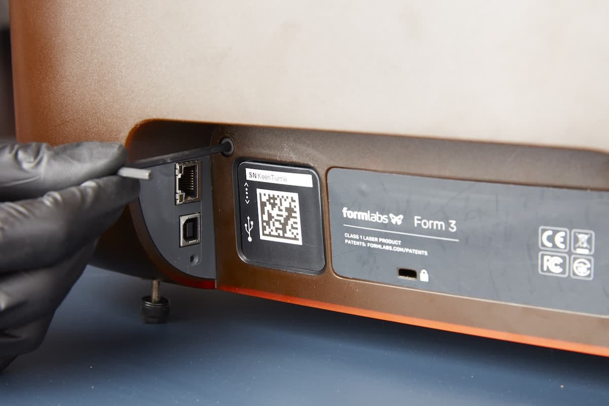
Rotate the printer to access the rear. Use a 3 mm hex driver to loosen and remove the two screws on the back of the printer, near the power and data ports.
Step 3: Remove the rear shell
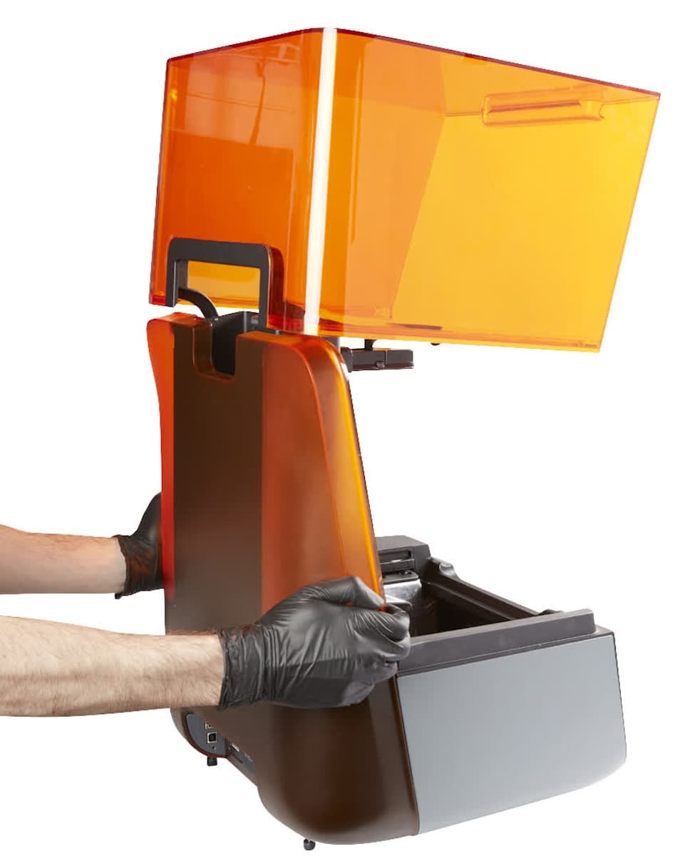
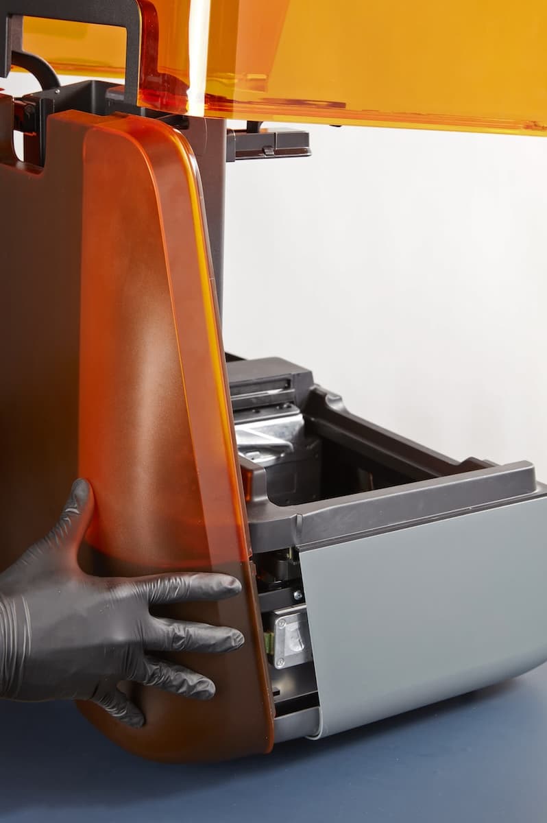
Gently flex the sides of the rear shell outwards to unclip it from the printer frame. Pull the rear shell directly away from the printer to remove it. Set the rear shell aside.
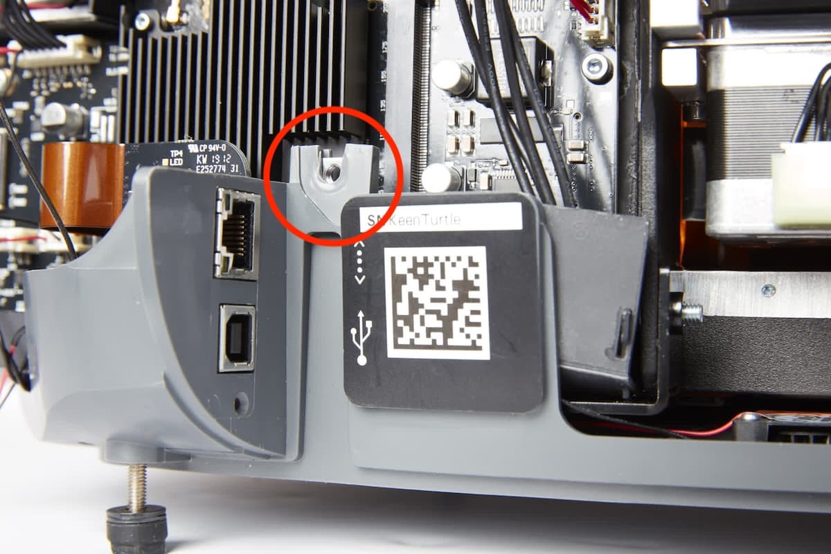
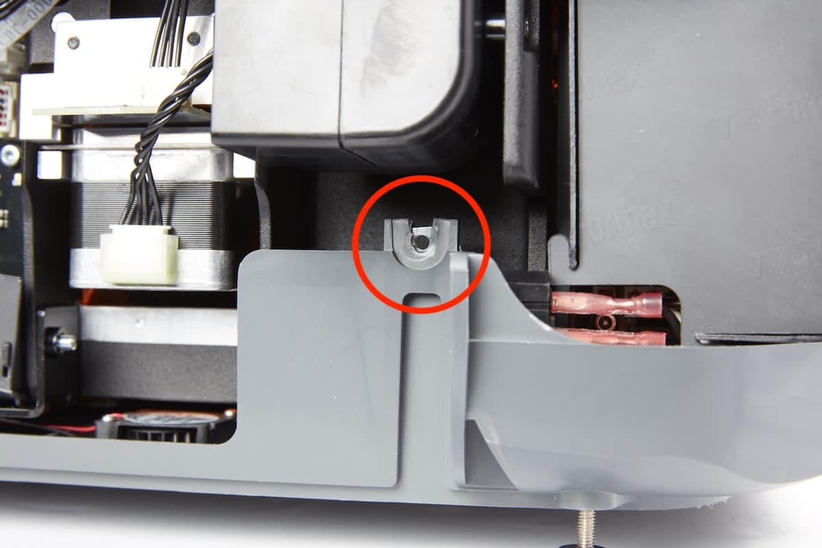
Locate—but do not remove—the two nuts, retained in the lower shell, that previously secured the external rear shell screws. Ensure that they did not come loose while removing the rear shell.
Removing the cartridge floor
Overview: Unscrew, unplug, and remove the cartridge floor.
Step 1: Unscrew the cartridge floor screws
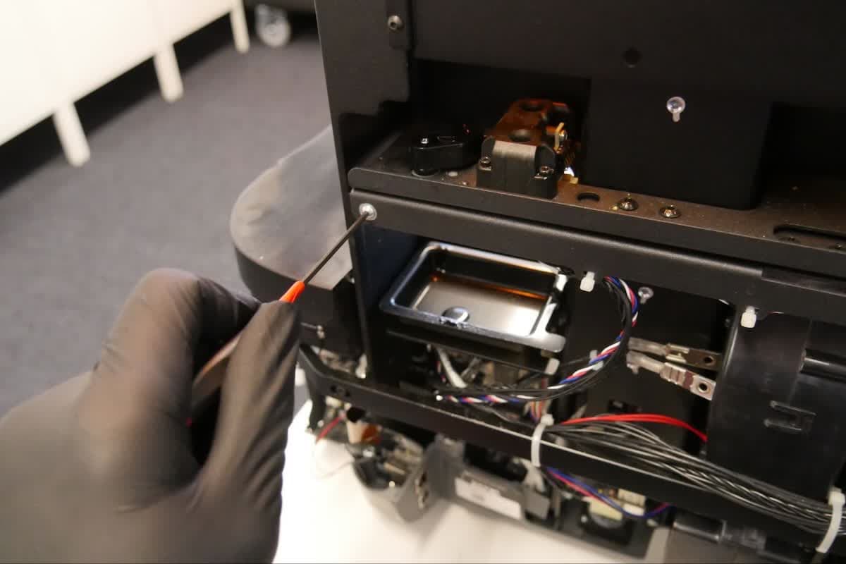
Using the 2 mm hex driver, unscrew the two screws securing the cartridge floor to the printer frame. Set the screws aside.
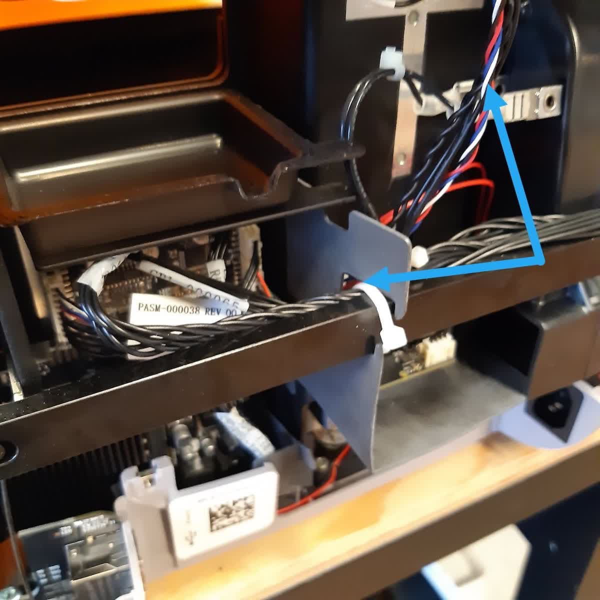
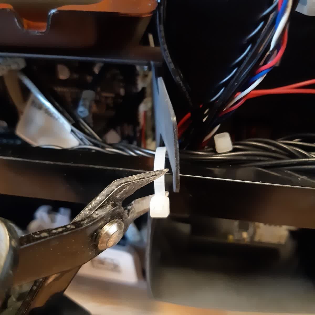
Step 2: Cut the cartridge floor cable zip tie (optional)
The cartridge floor cable may be zip tied to the printer frame. If so, cut the zip tie to release the cable.
Step 3: Unplug the cartridge floor cable
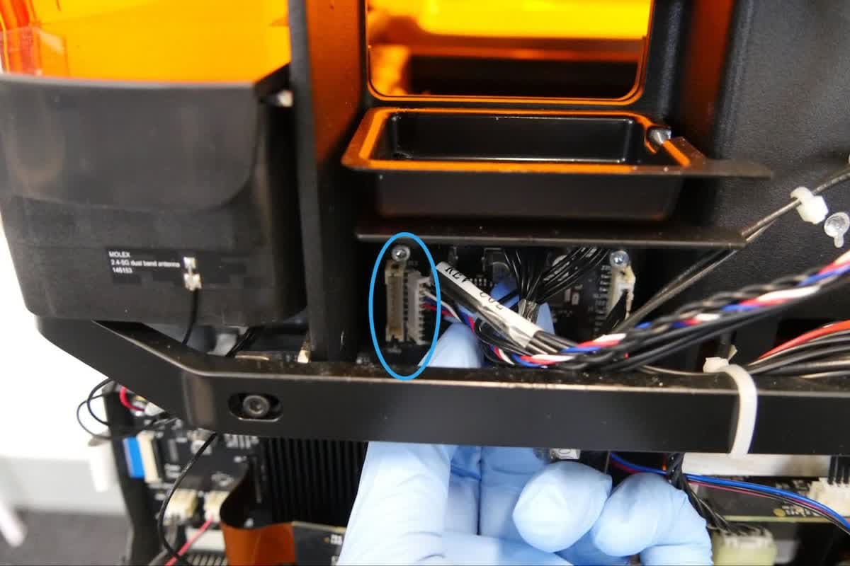
Locate the cartridge floor cable. Hold the connector by its plastic housing and disconnect the cable from the printer's motherboard. Do not pull on the individual wires.
Step 4: Remove the cartridge floor
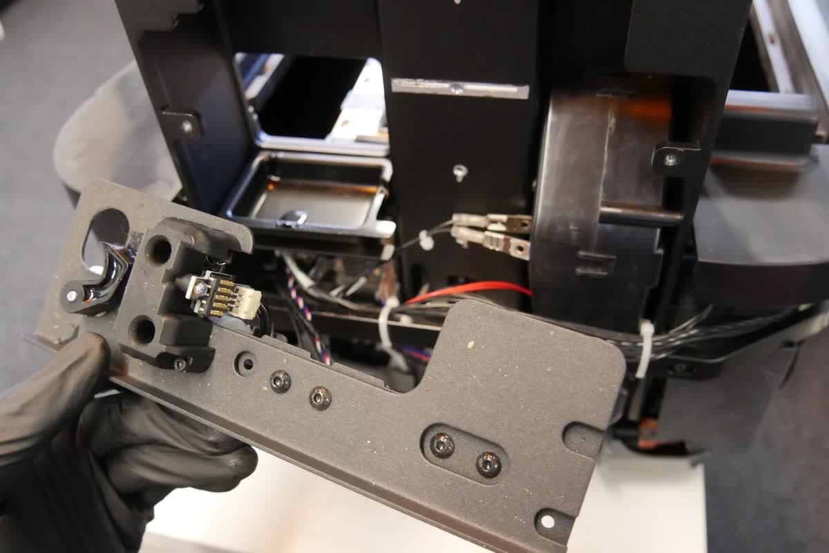
Carefully lift the cartridge floor above its mounting points and away from the printer. Set aside. Clean the cartridge floor of any liquid resin before disposal.
Installing the cartridge floor
Overview: Install the new cartridge floor.
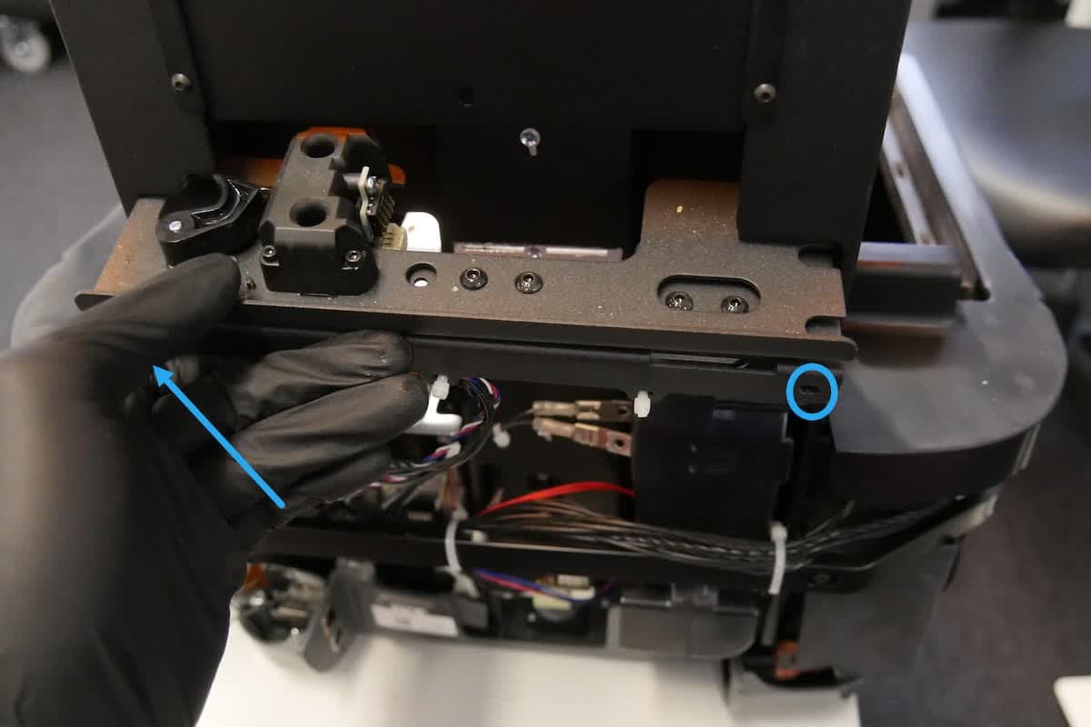
Step 1: Mount the cartridge floor
Slide the cartridge floor into the space directly above its mounting points. Lower the cartridge floor into place so that the screw holes in the face of the cartridge floor are aligned with the screw holes in the printer frame.
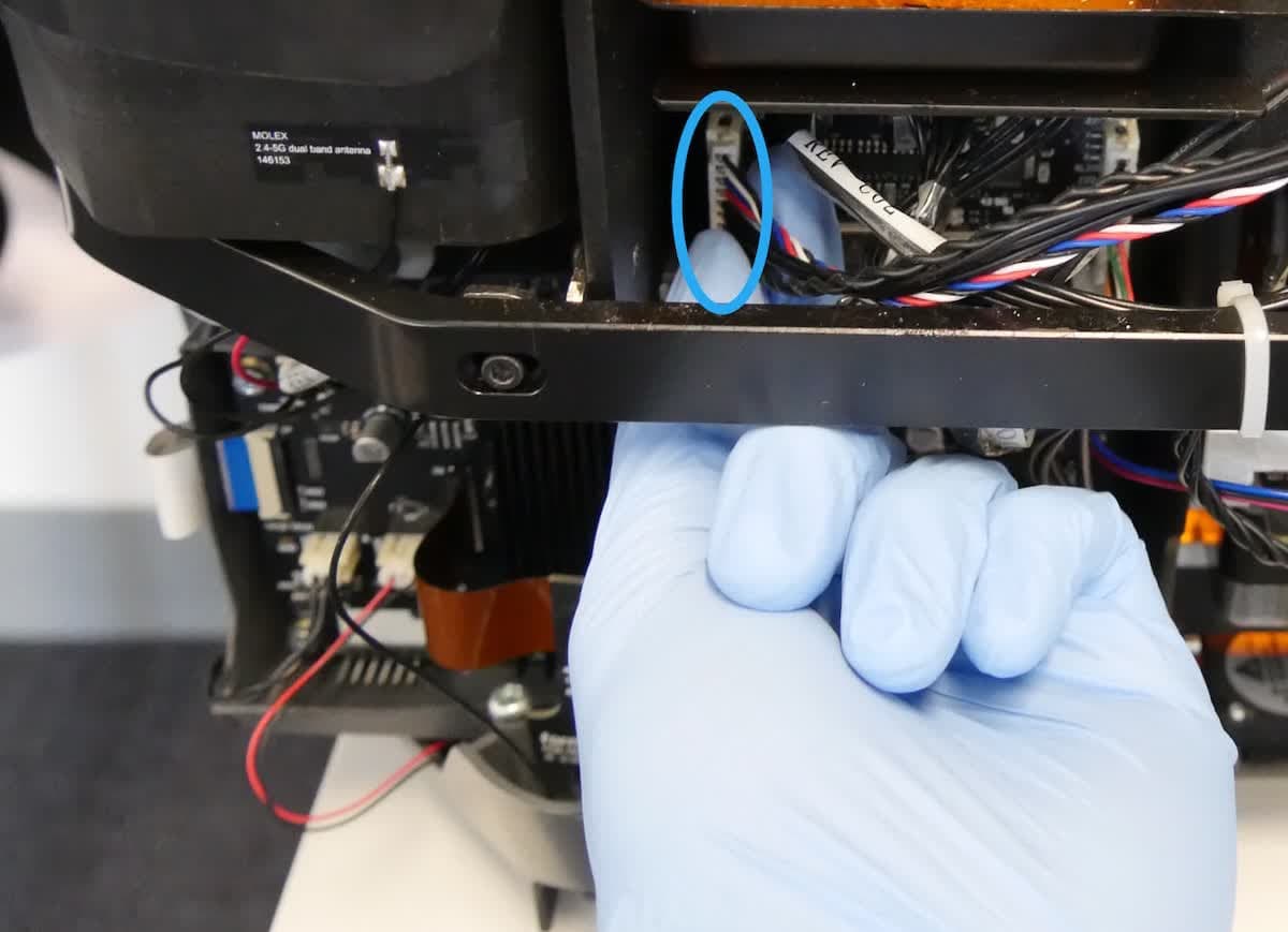
Step 2: Plug in the cartridge floor cable
Plug the cartridge floor cable into the printer's motherboard. The cable will only enter the connector in the correct orientation. Be careful not to bend the pins in the connector. Do not pull on the individual wires.
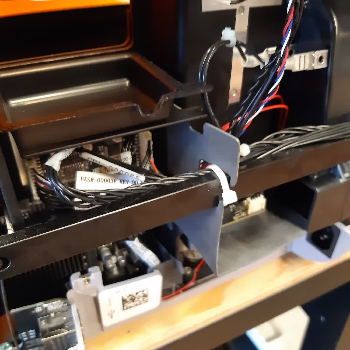
Some printers may have a plastic divider to organize the cables. If your printer has this, route the cartridge floor cable through the gap in the divider before plugging it in.
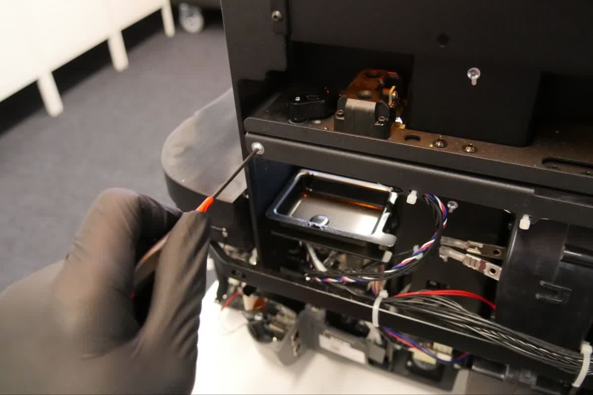
Step 3: Secure the cartridge floor
Insert the two cartridge floor screws into their respective holes in the cartridge floor. Tighten the screws with the 2 mm hex driver until finger tight.
Reinstalling the rear shell
Overview: After performing any other maintenance procedures, reinstall and secure the rear shell.
Step 1: Replace the rear shell
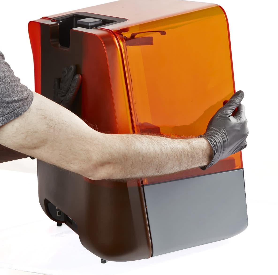
Place the rear shell back onto the printer. Press it towards the front of the printer to ensure that it fully seats in place. There should be no gaps between the rear shell and the side or bottom shells.
Step 2: Secure the rear shell
Using a 3 mm hex driver, screw the two 3 mm hex screws into the rear of the printer.
Open the printer cover. Using a 2 mm hex driver or a T10 Torx driver (depending on the type of screws in your printer), screw the two Z-tower screws into the sides of the Z-tower.
Finalizing the repair
Overview: After installing the new cartridge floor, power on the printer and perform final checks.
Step 1: Power on the printer
Close the printer cover and connect the power cable to the printer and the power supply. The printer initializes.
Step 2: Test the repair
Insert a resin cartridge into the printer and check that the printer detects it properly. Insert a resin tank and build platform, then start a print and check that the printer dispenses resin properly. Contact Formlabs Support or your authorized reseller to share the results of the procedure.