
Required supplies:
Formlabs:
- Replacement nitrogen ball valve (RP-FS1P-NV-01)
Third-party:
- 2 mm hex driver (flat-end)
- 2.5 mm hex driver (flat-end)
- Slotted screwdriver
- T20 Torx driver
- Thread seal tape
- Adjustable wrench

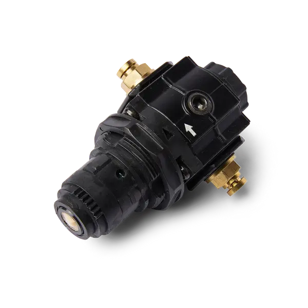
On Fuse 1+ 30W printers, the nitrogen ball valve controls the flow of nitrogen into the print enclosure when printing with an inert gas atmosphere. A faulty or malfunctioning ball valve may prevent you from printing with nitrogen.
Use this guide to replace the nitrogen ball valve on a Fuse 1+ 30W printer.
Required supplies:
Formlabs:
Third-party:
Estimated time: 45–60 minutes
Danger:
Read and follow all safety instructions and warnings in the operator manual. Replacement with incorrect parts can lead to burns, shock, fire, or explosion. Dispose of all parts in accordance with local regulations.
Preparing the workspace
Overview: Prepare the printer and a dust-free workspace for replacing the nitrogen ball valve.
Notice:
Fuse 1 generation printers contain sensitive electronic components. Ground yourself before touching any electronics in the printer by using a grounding strap or touching a grounded piece of metal.
Step 1: Prepare the workspace
Clear a workspace around your printer. Ensure that the workspace is well-ventilated and free of dust.
Step 2: Unplug the printer
Disconnect the power cable before continuing with maintenance. Do not perform maintenance on the printer while it is connected to power. Wait five minutes after disconnecting the printer from power before proceeding.
Danger:
Performing maintenance on the printer while it is plugged in increases the risk of electric shock. Never remove the back panel of the printer while the printer is plugged in. Never reconnect the printer to power while the back panel is uninstalled.
Step 3: Disconnect the nitrogen source
Disconnect the nitrogen hose from the quick-disconnect fitting, if connected.
Step 4: Remove the Wi-Fi antenna
Unscrew and remove the Wi-Fi antenna, if it is connected.
Removing the rear panels
Overview: Remove the rear panels to access the interior of the printer.
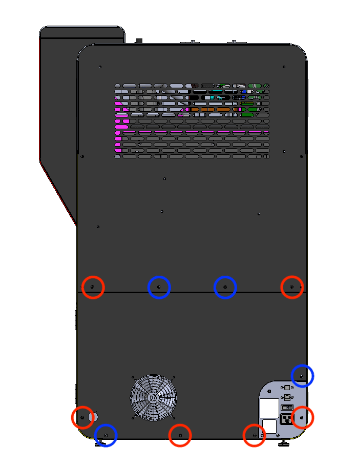
The six black lower rear panel screws are circled in red. The four chrome lower rear panel grounding screws are circled in blue.
Using a 2.5 mm hex driver, remove the six black panel screws and the four chrome panel grounding screws securing the lower rear panel to the printer. Set the screws aside, taking care to separate the black and chrome screws for later reinstallation.
Pull the lower rear panel straight back and away from the printer. Lay it down on a flat, clean surface.
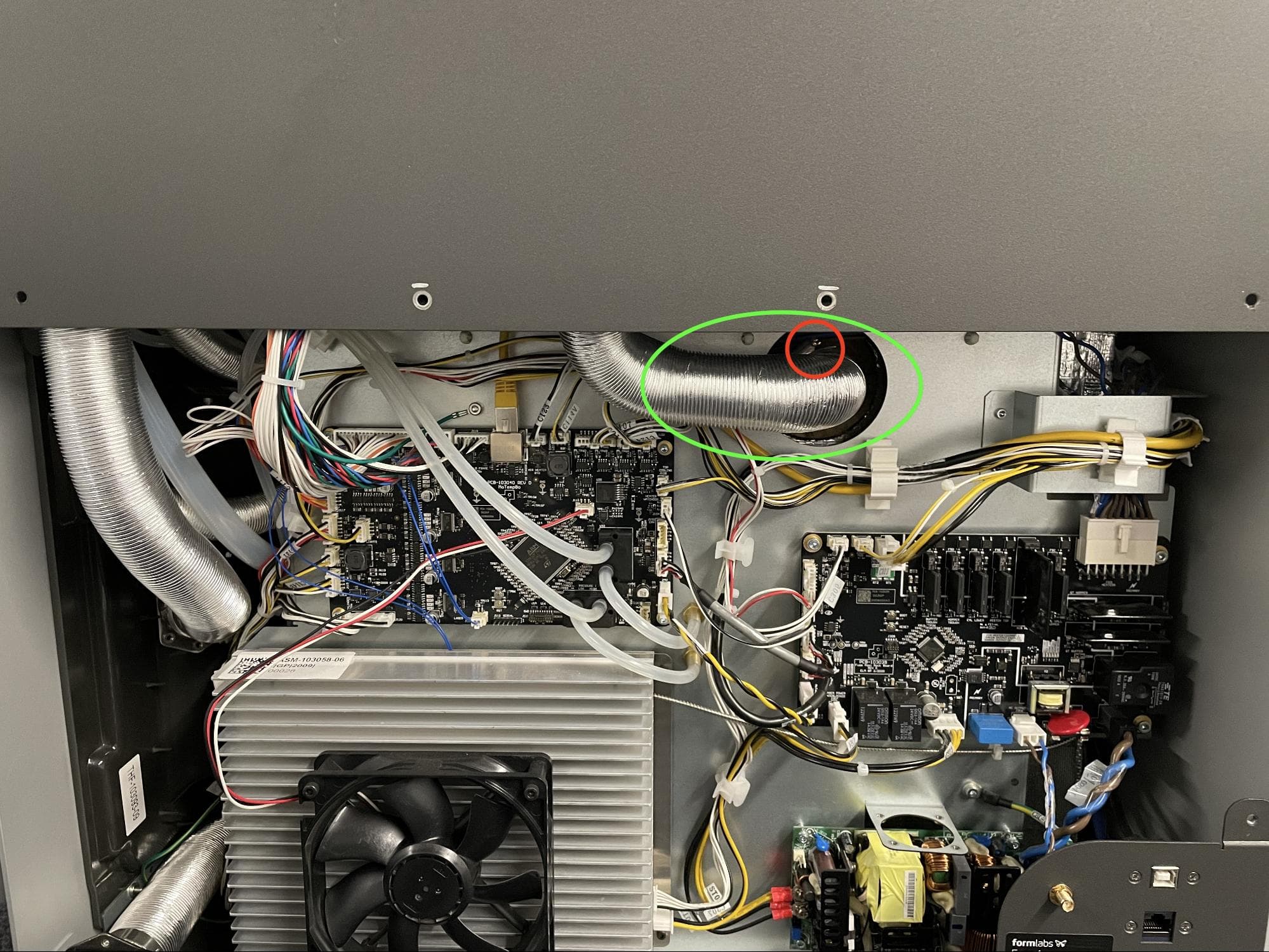
Locate the ring clamp attached to the exhaust duct in the center of the printer.
Using a 6.5 mm flathead screwdriver, loosen the ring clamp screw. Do not remove the screw. Pull the exhaust duct away from the exhaust pipe.
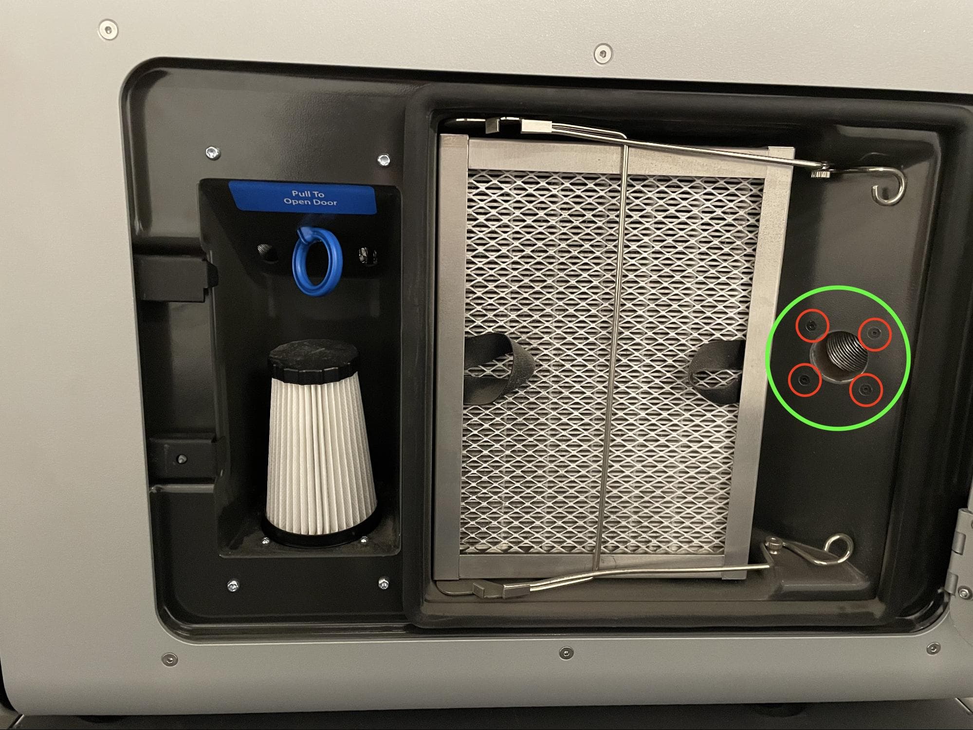
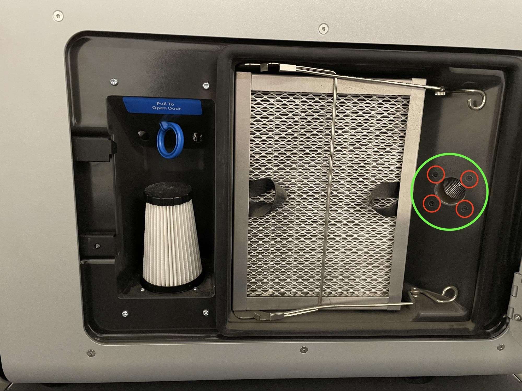
Open the filter cabinet door on the printer. Locate the exhaust inlet on the right side of the cabinet.
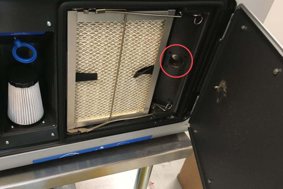
Using a 2.0 mm hex driver, remove the four screws attaching the exhaust inlet to the filter cabinet. Set the screws aside.
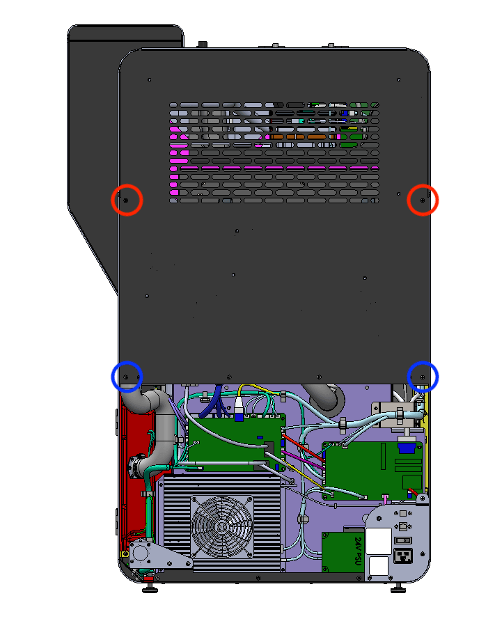
The two black upper rear panel screws are circled in red. The two chrome upper rear panel grounding screws are circled in blue.
Using a 2.5 mm hex driver, remove the two black panel screws and two chrome panel grounding screws securing the upper rear panel to the printer. Set the screws aside, taking care to separate the black and chrome screws for later reinstallation.
Step 8: Remove the upper rear panel screws
Using a 2.5 mm hex driver, remove the eight screws securing the upper rear panel to the printer:
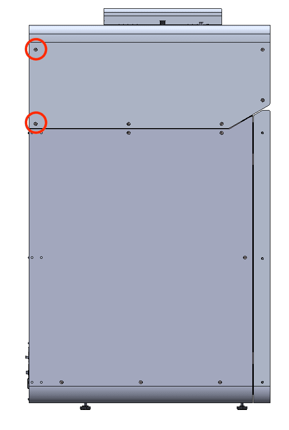
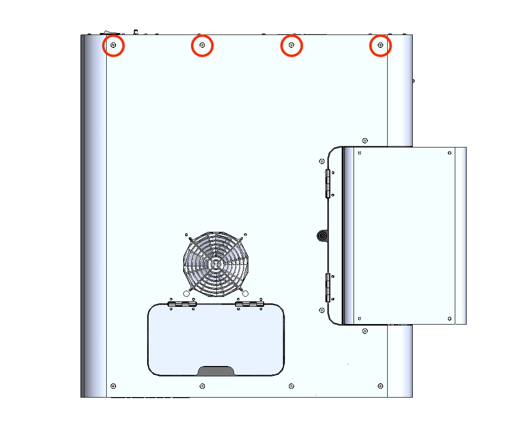
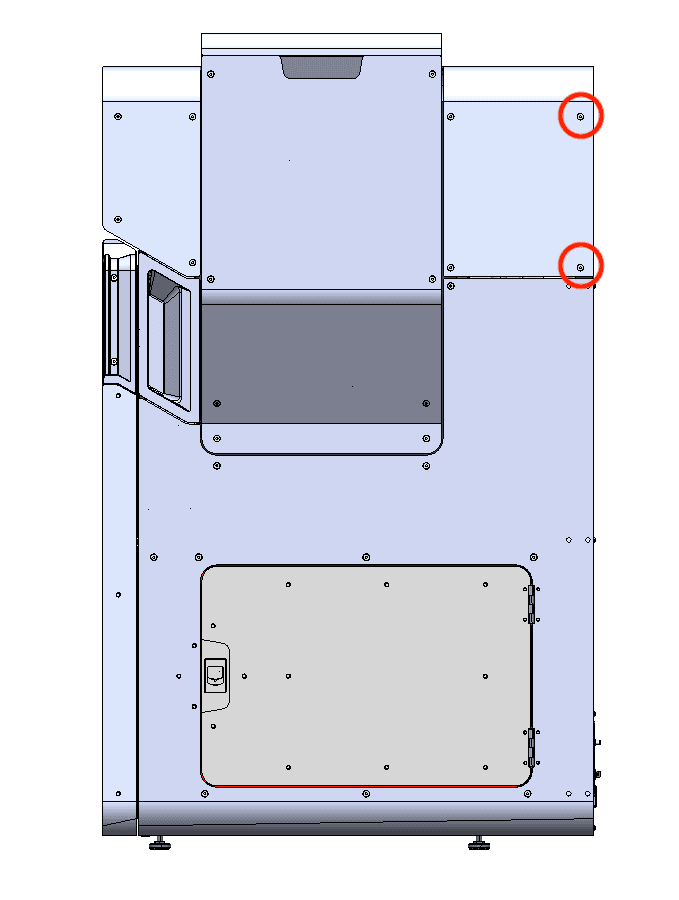
Set the screws aside.
Step 9: Remove the upper rear panel
Pull the upper rear panel straight back and away from the printer. Lay it down on a flat, clean surface.
Removing the top panel
Overview: Remove the top panel to access the interior of the printer.
Step 1: Remove the top panel screws
Using a 2.5 mm hex driver, remove the 18 6 mm M4 countersunk screws securing the top panel to the printer:
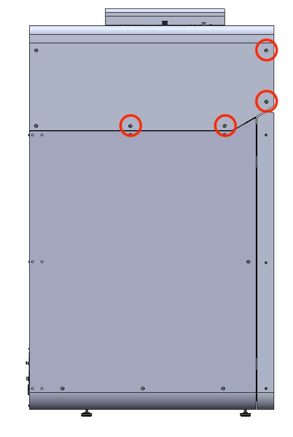
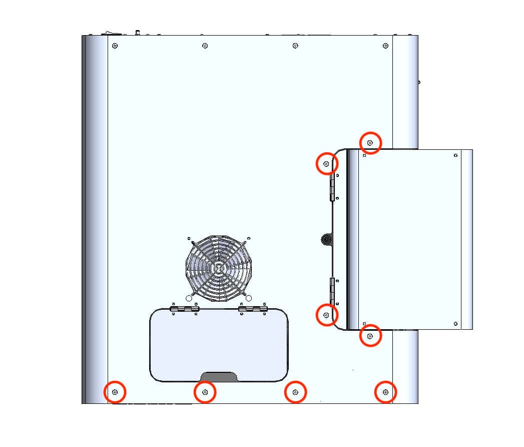
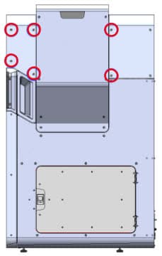
Set the screws aside.
Step 2: Remove the top panel
Lift the top panel off of the printer by grabbing the IR sensor door and the rear-most edge. Set the top panel aside.
Removing the nitrogen ball valve
Overview: Disconnect and remove the original nitrogen ball valve
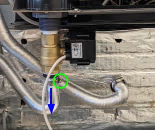
Locate the ball valve, positioned at the back of the printer. Using a slotted screwdriver, loosen the ring clamp on the bottom of the valve and disconnect the air intake tube.
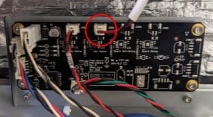
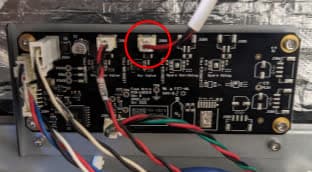
Disconnect the ball valve cable from plug labeled J088 on the nitrogen controller board below it.
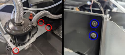
The nitrogen ball valve is attached to the bottom of the nitrogen plenum. Using a T20 Torx driver and a 2.5 mm hex driver, remove the three T20 Torx screws (on top) and two M3 socket head screws and washers (on the hopper-side) that secure the nitrogen plenum to the printer. Set the screws aside.
Using a slotted screwdriver, loosen the two ring clamps on the nitrogen plenum and disconnect the aluminum tubes. On newer printers, there will be a white rubber gasket underneath the tube at the top of the plenum. This can remain in place. Disconnect the silicone pressure tap tube.
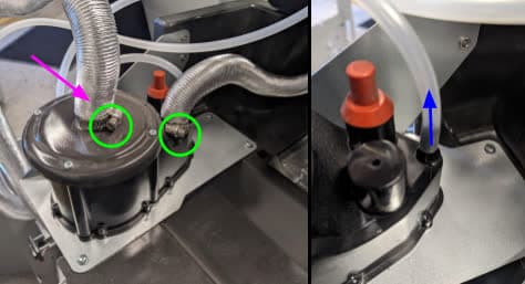
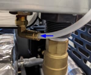
Locate the brass elbow fitting towards the rear hopper side of the printer, next to the ball valve. Push the brass ring down while pulling on the plastic tube to disconnect it.
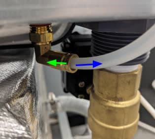
Remove the plenum assembly from the printer and set it down on a flat surface.
Either by hand or with an adjustable wrench, unscrew the nitrogen ball valve from the rest of the assembly as shown.
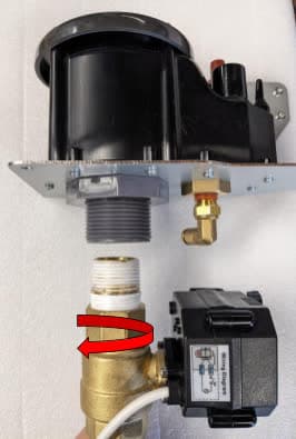
Installing the replacement nitrogen ball valve
Overview: Mount, secure, and connect the replacement nitrogen ball valve.
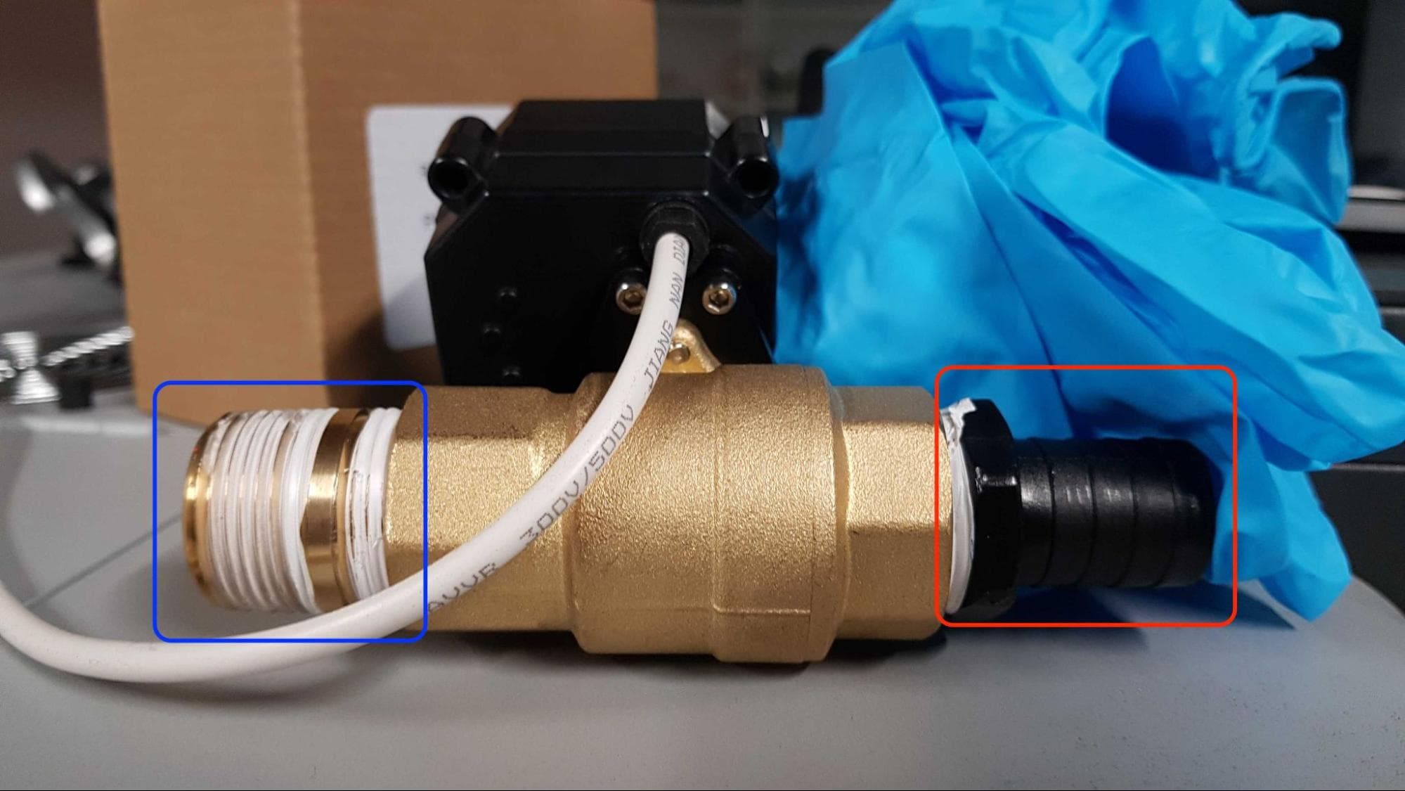
If the replacement nitrogen ball valve does not come with the plastic barb fitting and the brass straight fitting pre-installed, apply one to two turns of thread seal tape to the threads in a clockwise motion, then use an adjustable wrench to secure the fittings to the valve as shown.
Apply one or two turns of thread seal tape to the remaining threads of the brass straight fitting, if it has not been preapplied.
Either by hand or with an adjustable wrench, screw the new nitrogen ball valve into the plenum assembly until it is fully screwed in and the gearbox is in the orientation shown.
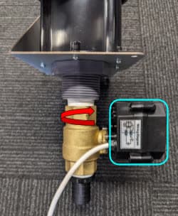
Reinstall the plenum assembly with the new valve onto the top rear of the printer. Thread the mounting screws (three T20 Torx screws and two M3 socket head screws with washers) into the screw holes as shown. Using a T20 Torx driver and a 2.5 mm hex driver, tighten the screws until snug.
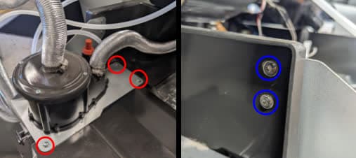
Reattach the silicone pressure tap tube to the nitrogen plenum. Reinstall the aluminum tubes and, using a slotted screwdriver, tighten the ring clamps until they are secure.
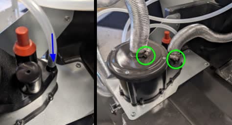
Locate the brass elbow fitting towards the rear hopper side of the printer, next to the ball valve. Push the plastic tube firmly into the fitting. After insertion, pull on the tube gently to ensure it does not come out.
Reconnect the ball valve cable to the plug labeled J088 on the nitrogen controller board.
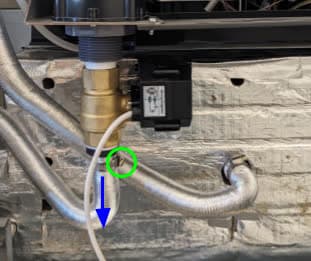
Reattach the air intake tube to the bottom of the ball valve. Using a slotted screwdriver, tighten the ring clamp until secure.
Reinstalling the top panel
Overview: After installing the replacement ball valve, reinstall and secure the top panel.
Step 1: Align the top panel
Lift the top panel and place it on top of the printer. Align the screw holes in the top panel with the corresponding holes in the printer frame.
Step 2: Secure the top panel screws
Thread a 6 mm M4 countersunk screw into each of the 18 marked screw holes in the top panel:
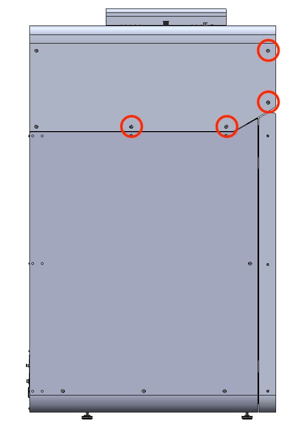
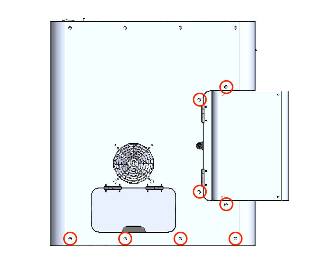
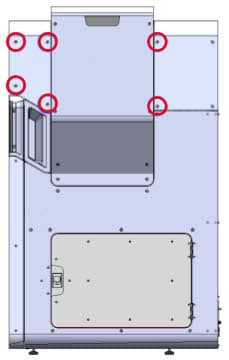
Using a 2.5 mm hex driver, tighten the screws until snug.
Reinstalling the rear panels
Overview: After installing the replacement ball valve, reinstall and secure the rear panels.
Lift the upper rear panel and align it with the four screw holes on the top of the printer.
Thread the four 6.0 mm screws into each of the screw holes on the top of the printer. Using a 2.5 mm hex driver, tighten the screws until finger tight. You may need to adjust the exhaust duct to correctly position the upper rear panel.
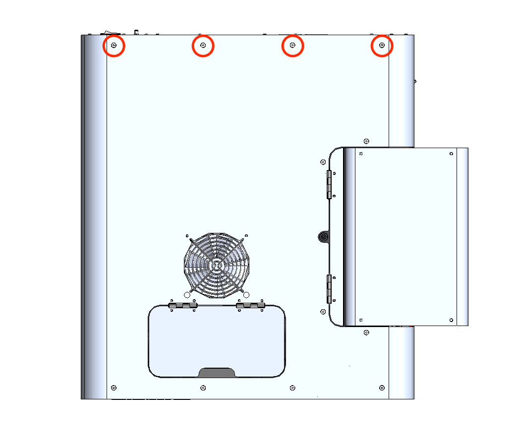
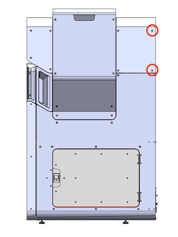
Thread the two 6 mm screws into the screw holes on the buffer side and the two 6 mm screws into the screw holes on the hopper side. Using a 2.5 mm hex driver, tighten the screws until snug.
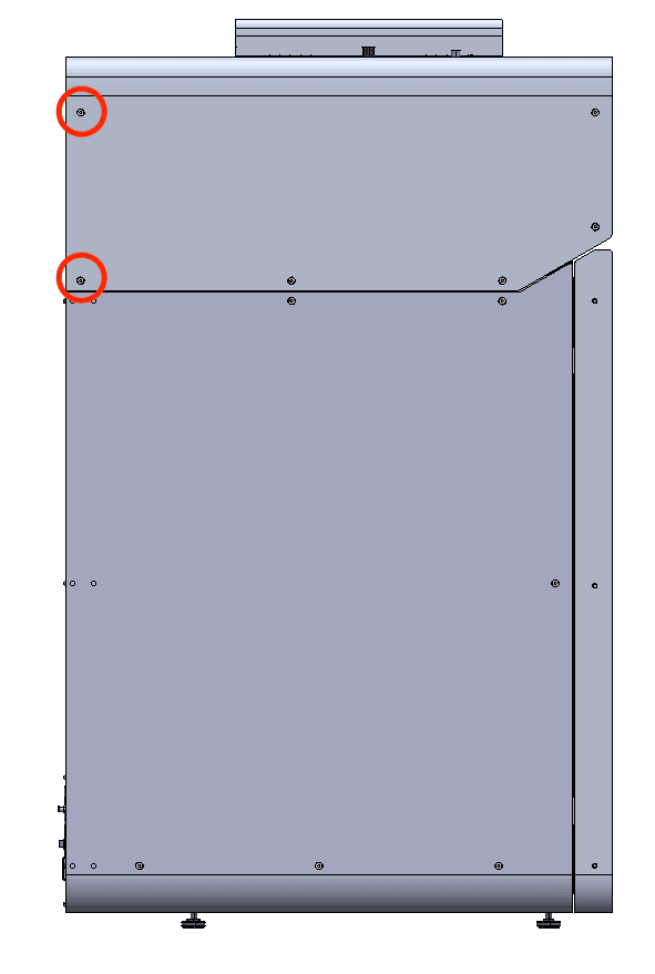
Thread the two 6mm screws into the holes on the hopper side. Using a 2.5 mm hex driver, tighten the screws until snug.
The two black upper rear panel screws are circled in red. The two chrome upper rear panel grounding screws are circled in blue.
Thread the panel screws into the indicated screw holes on the upper rear panel. Refer to the image for the correct locations of the black and chrome screws. Using a 2.5 mm hex driver, screw in the two black panel screws and two chrome grounding screws securing the upper rear panel to the printer.
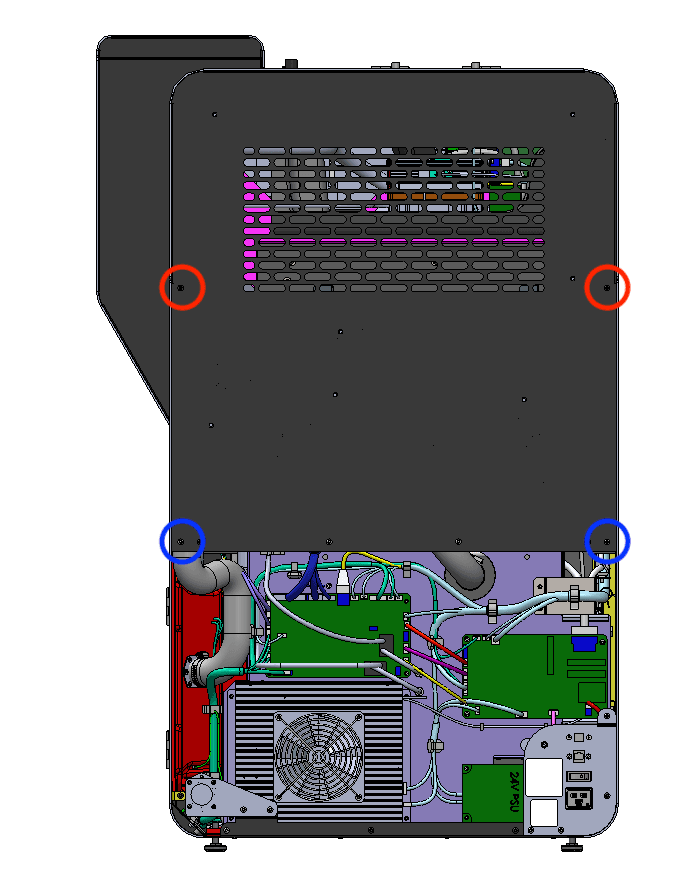
Notice:
The placement of the chrome screws is critical to the printer's electrical grounding. Incorrect placement may lead to printer damage.
Step 6: Slide the exhaust duct into position
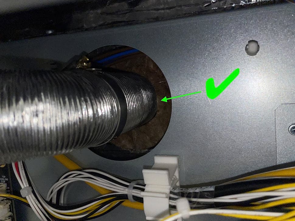
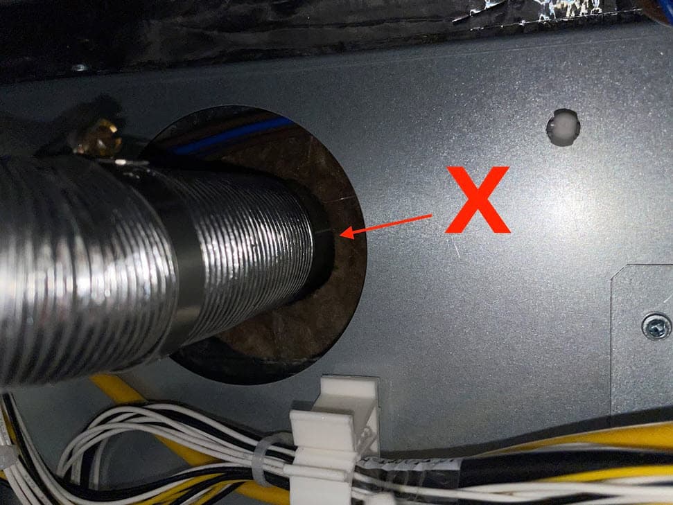
Slide the end of the exhaust duct with the ring clamp back onto the exhaust pipe. Ensure the exhaust duct presses against the insulation panel.
Step 7: Tighten the exhaust duct ring clamp
Using a 6.5 mm flathead screwdriver, tighten the ring clamp until finger tight.
Open the filter cabinet door on the printer. Thread the four 8.0 mm screws into the screw holes. Using a 2.0 mm hex driver, screw in the four exhaust duct screws until finger tight.
To ensure there is no gap between the exhaust duct’s mounting plate and the filter cabinet housing, shine a flashlight or other light source around the exhaust inlet inside the filter cabinet. If any light is visible behind the filter cabinet, the duct is not properly sealed. If necessary, use a 2.0 mm hex driver to tighten the exhaust duct screws. Close the filter cabinet door when finished.
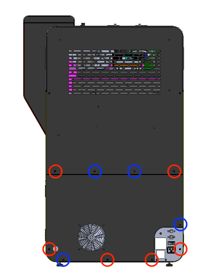
The six black lower rear panel screws are circled in red. The four chrome lower rear panel grounding screws are circled in blue.
Thread the panel screws into the indicated screw holes on the lower rear panel. Refer to the image for the correct locations of the black and chrome screws. Using a 2.5 mm hex driver, screw in the six black panel screws and four chrome panel grounding screws securing the lower rear panel to the printer.
Notice:
The placement of the chrome screws is critical to the printer's electrical grounding. Incorrect placement may lead to printer damage.
Step 11: Reinstall the Wi-Fi antenna (optional)
Screw the Wi-Fi antenna onto the jack on the back of the unit.
Step 12: Reconnect the nitrogen supply
Reconnect the nitrogen hose to the quick-disconnect fitting.
Finalizing the repair
Overview: After installing the replacement nitrogen ball valve, power on the printer and perform final checks.
Step 1: Power on the printer
Connect the power cable to the printer and the power supply. The printer initializes.
Step 2: Check the nitrogen supply
Confirm that nitrogen supply pressure into the Fuse 1+ 30W is in the range of 248–862 kPa (36–125 psi) and the flow rate is at least 14 L/min (0.5 SCFM). When using a nitrogen supply such as bottled nitrogen gas or liquid nitrogen, ensure that there is enough available nitrogen to complete the print. When printing with an inert gas atmosphere, the printer requires approximately 14 L (0.5 cu ft) of nitrogen gas per minute.
Tap the printer icon in the left sidebar to access the printer status screen. Toggle Nitrogen System to ON. Confirm that the touchscreen shows N2 Mode and that both the Inlet Pressure and the Valve Pressure are in range.
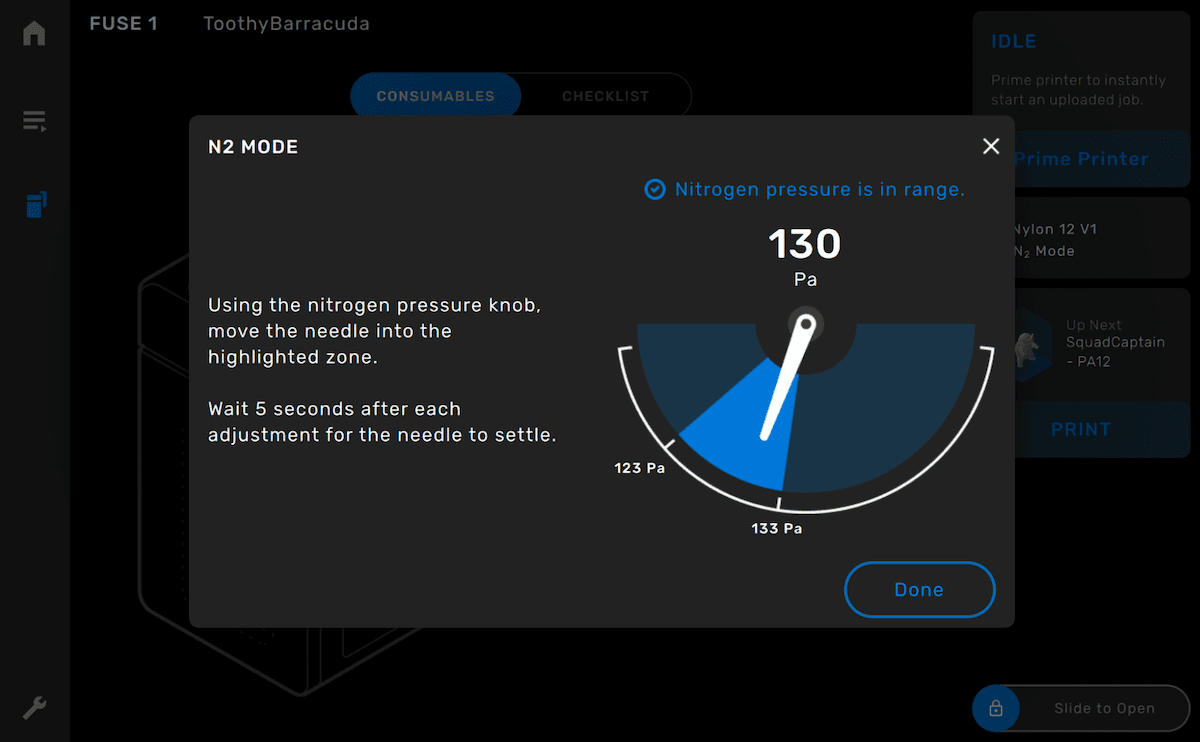
Step 4: Test the repair
Start a print using nitrogen. Monitor the printer to ensure that the print proceeds normally. Contact Formlabs Support or your certified service provider to share the results of the procedure.