WHITE PAPER
Formlabs Logo

Replacing the Fuse 1 hopper trough RTD

Replacing the Fuse 1 hopper trough RTD

The Fuse 1 uses multiple heaters to bring the powder up to the proper temperature for sintering. A faulty or malfunctioning resistance temperature detectors (RTD) on the hopper trough heater will prevent the printer from working properly.

Use this guide to replace the hopper trough heater RTD on a Fuse 1 printer. To replace this component on a Fuse 1+ 30W printer, see Replacing the Fuse 1+ 30W hopper trough heater RTD or heater.

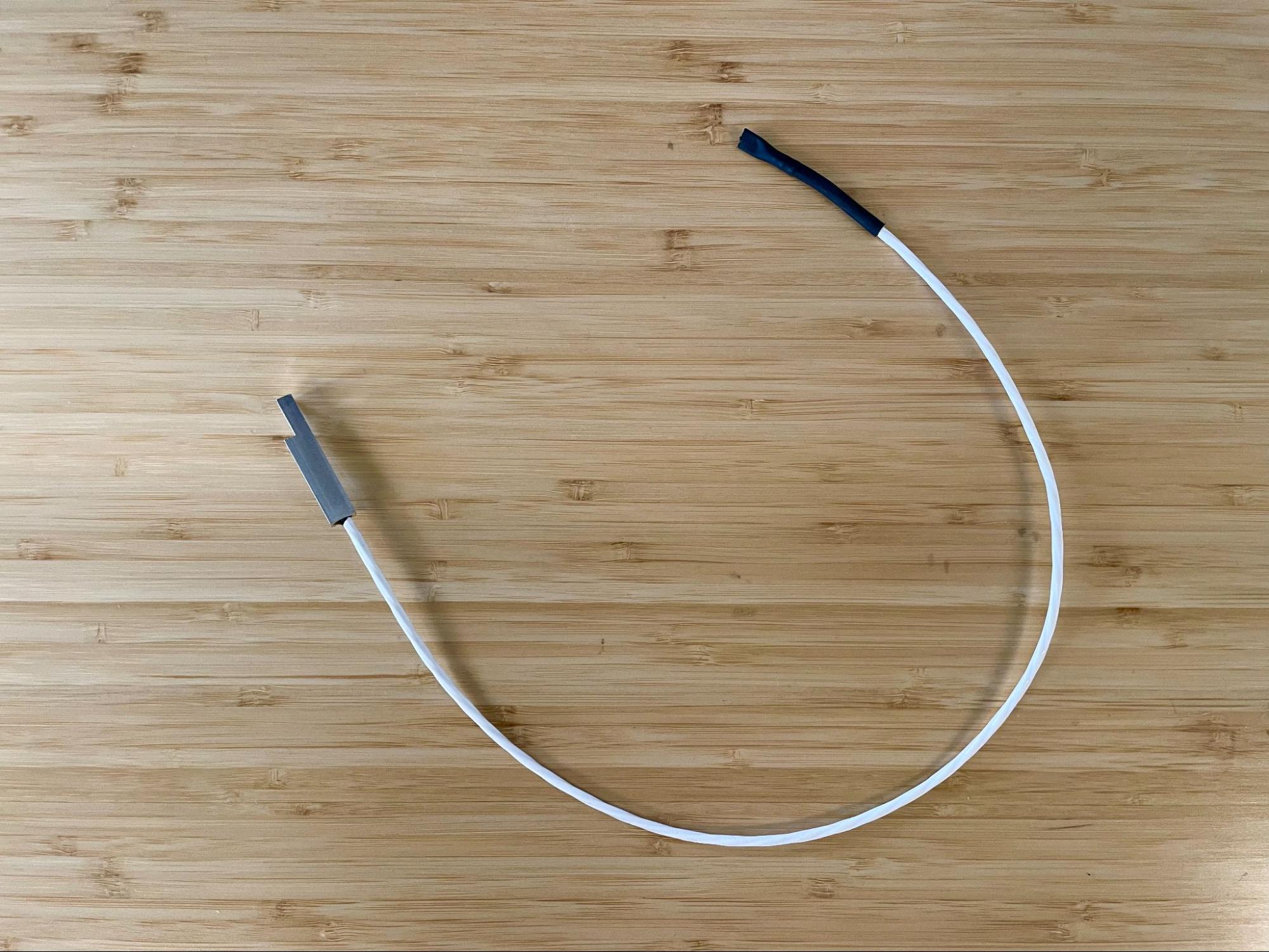
Fuse 1 hopper trough RTD

Required supplies:

Formlabs:

Third-party:

  • 2 mm hex driver (flat-end)
  • 2.5 mm hex driver (flat-end)
  • 6.5 mm slotted screwdriver
  • Telescoping magnet wand
  • Utility knife
  • Flush cutters
  • Safety glasses
  • Nonreactive nitrile gloves
  • N95 or better respirator

Estimated time: 45–60 minutes

Danger:

Read and follow all safety instructions and warnings in the operator manual. Replacement with incorrect parts can lead to burns, shock, fire, or explosion. Dispose of all parts in accordance with local regulations.

Warning:

Do not perform this procedure if the printer was printing less than six hours prior. Failure to do so may result in serious burns. Allow the print enclosure to cool to room temperature before touching or inspecting any Fuse 1 components.

Preparing the workspace

Overview: Prepare the printer and a dust-free workspace for replacing the hopper trough RTD.

Notice:

Fuse 1 generation printers contain sensitive electronic components. Ground yourself before touching any electronics in the printer by using a grounding strap or touching a grounded piece of metal.

Step 1: Prepare the workspace

Clear a workspace around your printer. Ensure that the workspace is well-ventilated and free of dust.

Step 2: Unplug the printer

Disconnect the power cable before continuing with maintenance. Do not perform maintenance on the printer while it is connected to power. Wait five minutes after disconnecting the printer from power before proceeding.

Danger:

Performing maintenance on the printer while it is plugged in increases the risk of electric shock. Never remove the back panel of the printer while the printer is plugged in. Never reconnect the printer to power while the back panel is uninstalled.

Step 3: Remove the Wi-Fi antenna

Unscrew and remove the Wi-Fi antenna, if it is connected.

Removing the rear panels

Overview: Remove the rear panels to access the interior of the printer.

Step 1: Remove the lower rear panel screws

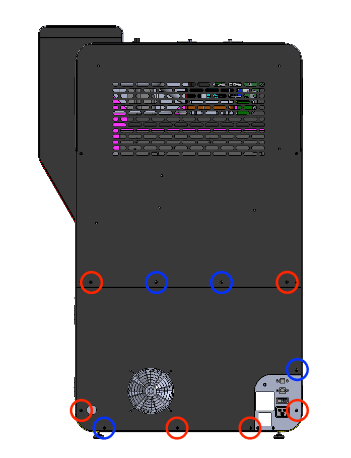
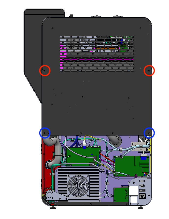
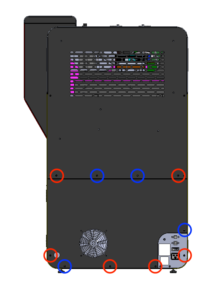
The six black lower rear panel screws are circled in red. The four chrome lower rear panel grounding screws are circled in blue.

Using a 2.5 mm hex driver, remove the six black panel screws and the four chrome panel grounding screws securing the lower rear panel to the printer. Set the screws aside, taking care to separate the black and chrome screws for later reinstallation.

Step 2: Remove the lower rear panel from the printer

Pull the lower rear panel straight back and away from the printer. Lay it down on a flat, clean surface.

Step 1: Remove the lower rear panel screws

Step 3: Locate the exhaust duct and ring clamp

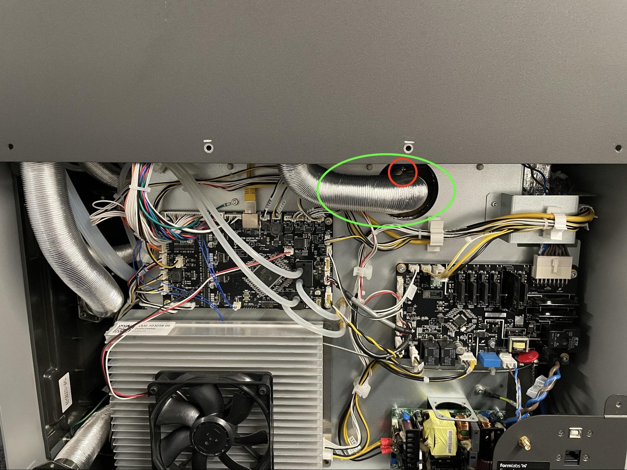
Locate the ring clamp attached to the exhaust duct in the center of the printer.

Step 4: Loosen the ring clamp screw

Using a 6.5 mm flathead screwdriver, loosen the ring clamp screw. Do not remove the screw. Pull the exhaust duct away from the exhaust pipe.

Step 3: Locate the exhaust duct and ring clamp

Step 5: Locate the exhaust inlet

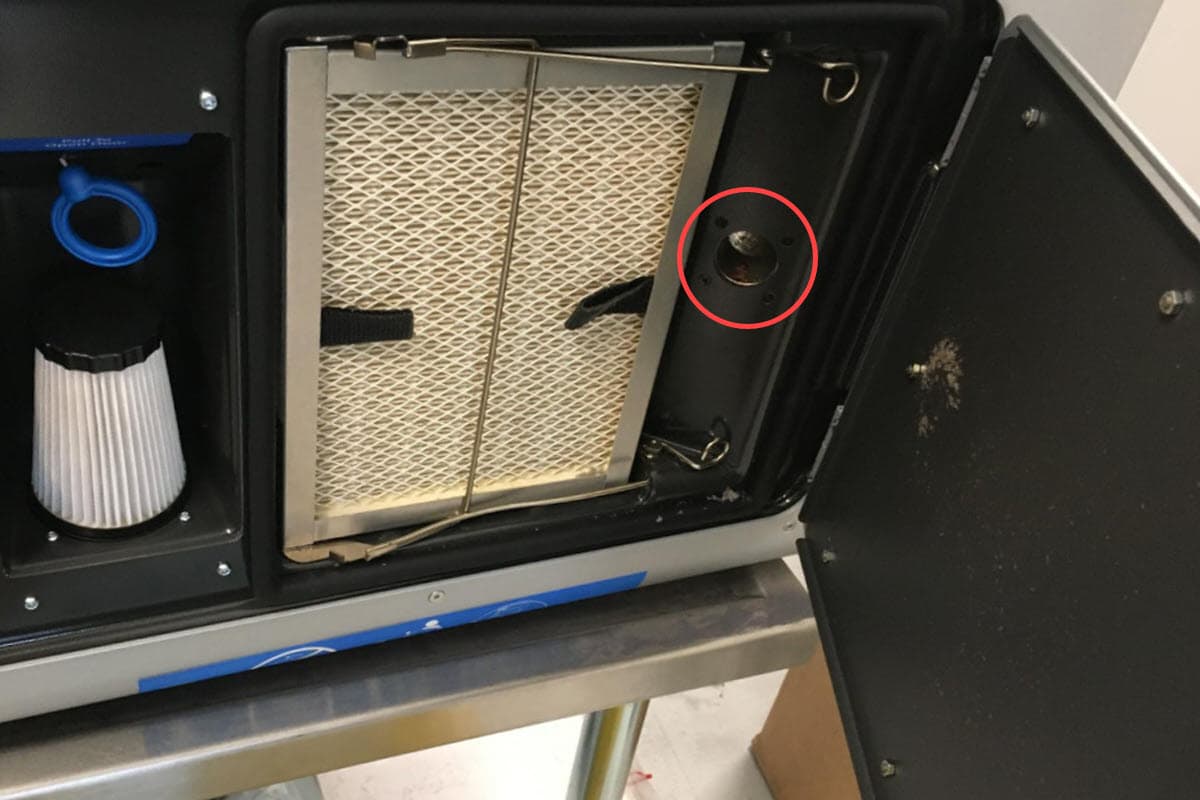
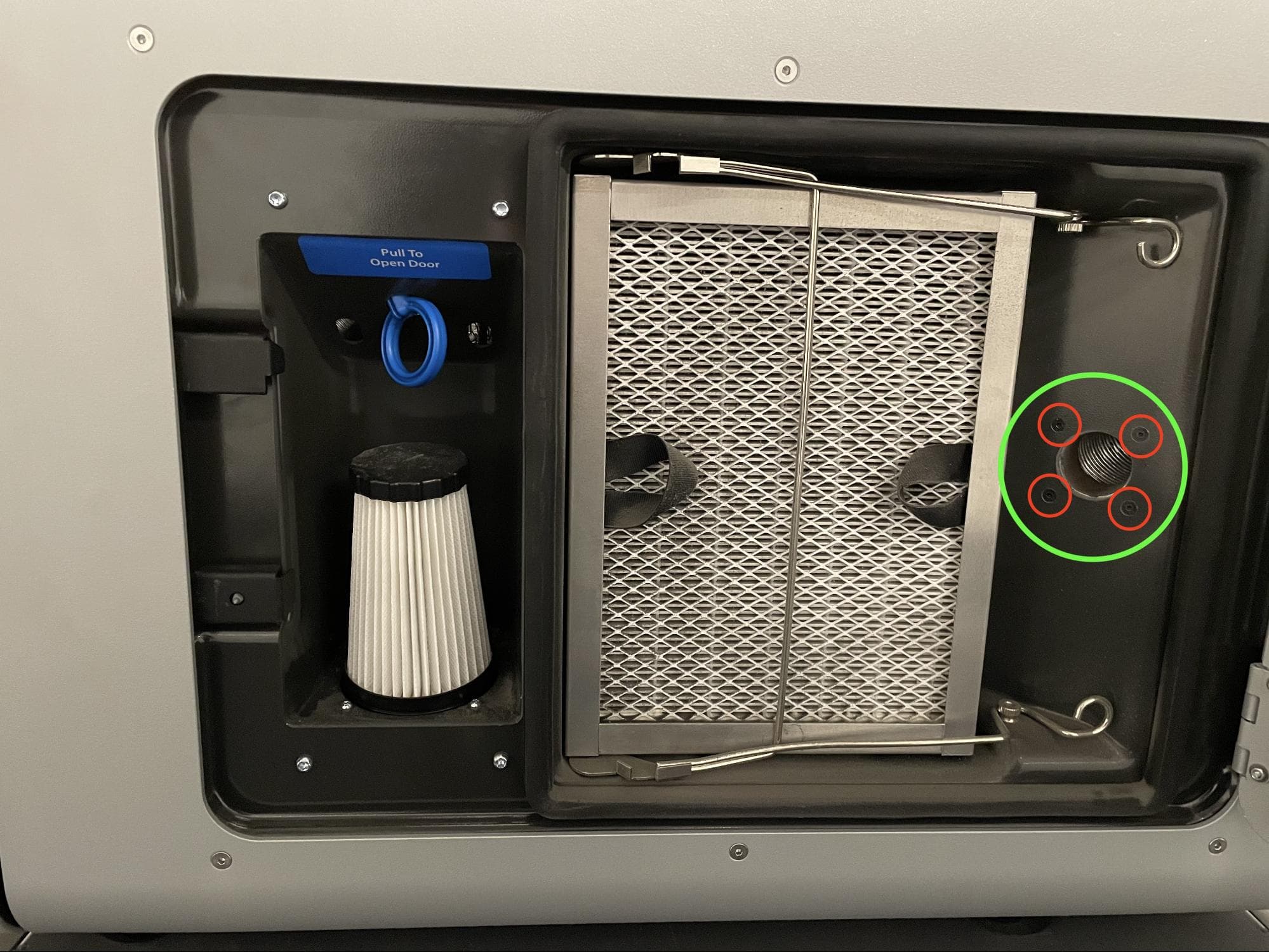
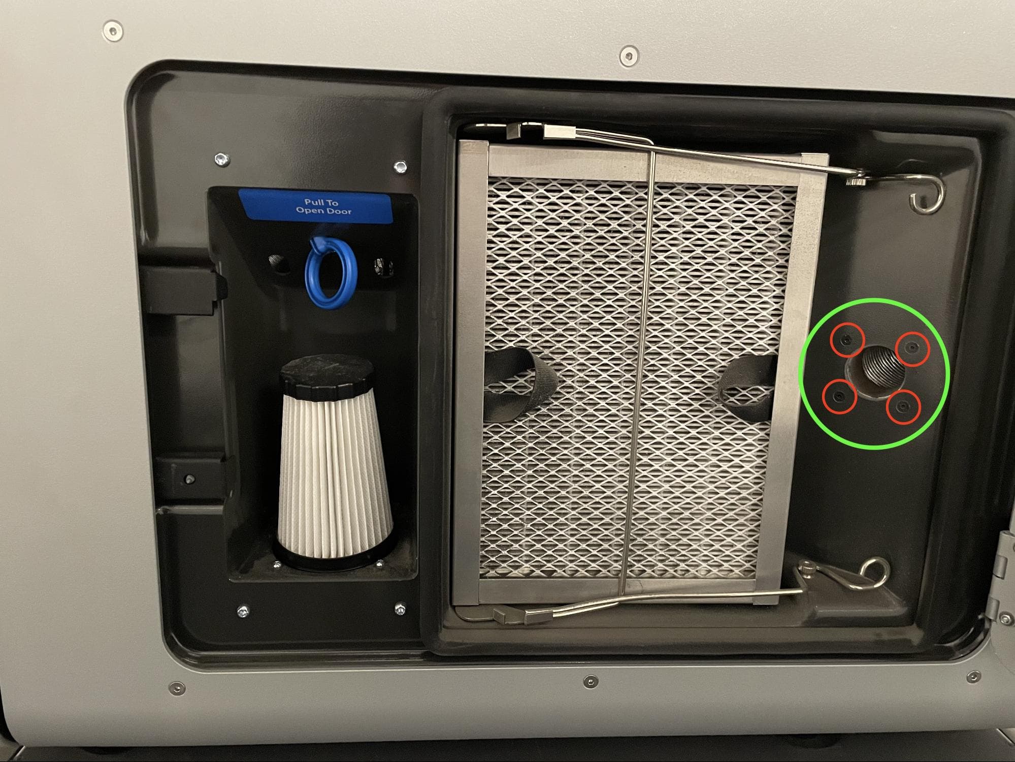
Open the filter cabinet door on the printer. Locate the exhaust inlet on the right side of the cabinet.

Step 5: Locate the exhaust inlet

Step 6: Remove the exhaust inlet screws

Using a 2.0 mm hex driver, remove the four screws attaching the exhaust inlet to the filter cabinet. Set the screws aside.

Step 6: Remove the exhaust inlet screws

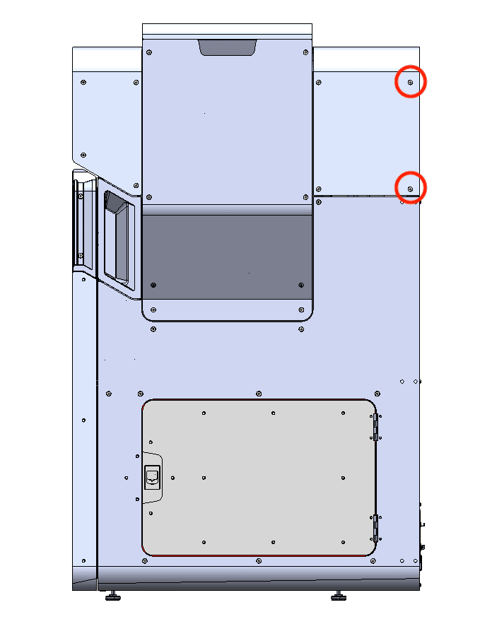
Step 7: Remove the upper rear panel screws

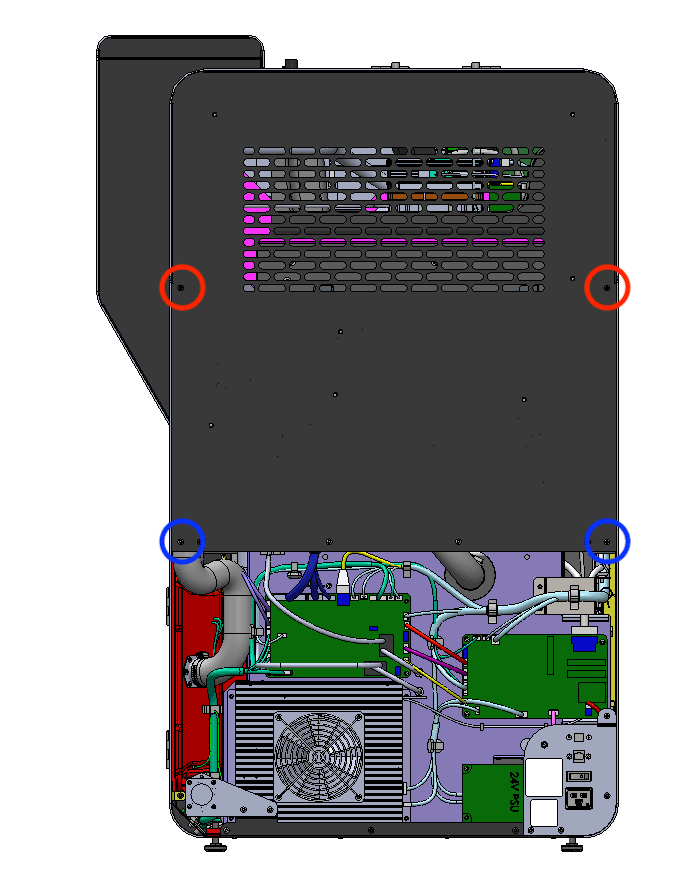
The two black upper rear panel screws are circled in red. The two chrome upper rear panel grounding screws are circled in blue.

Using a 2.5 mm hex driver, remove the two black panel screws and two chrome panel grounding screws securing the upper rear panel to the printer. Set the screws aside, taking care to separate the black and chrome screws for later reinstallation.

Step 7: Remove the upper rear panel screws

Step 8: Remove the upper rear panel screws

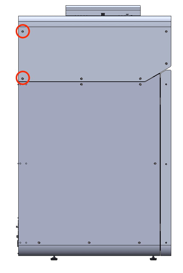
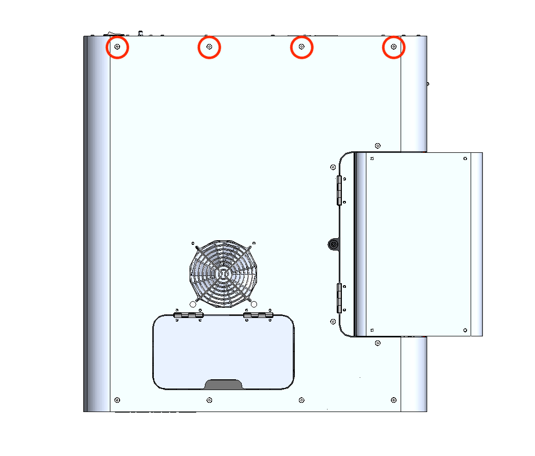
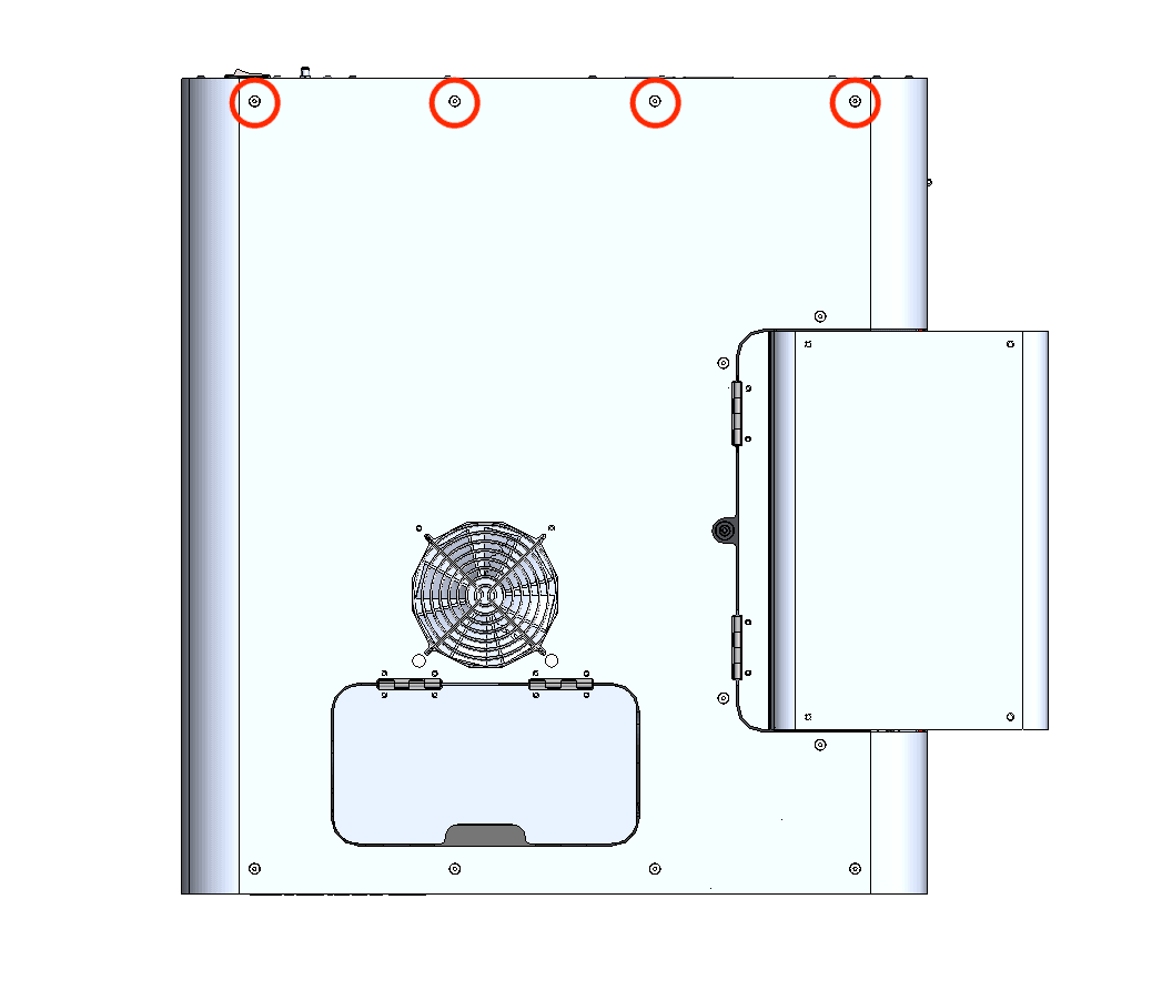
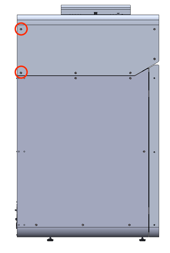
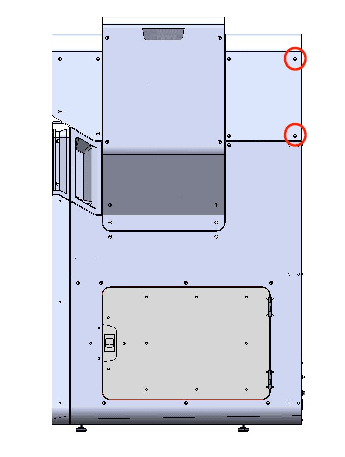
Using a 2.5 mm hex driver, remove the eight screws securing the upper rear panel to the printer:

Step 8: Remove the upper rear panel screws
  • Two 6 mm screws on the buffer side of the printer
  • Four 6 mm screws on the top of the printer
  • Two 6 mm screws on the hopper side of the printer

Set the screws aside.

Step 9: Remove the upper rear panel

Pull the upper rear panel straight back and away from the printer. Lay it down on a flat, clean surface.

Removing the original hopper trough RTD

Overview: Unplug and remove the original hopper trough RTD.

Step 1: Unplug the hopper trough RTD

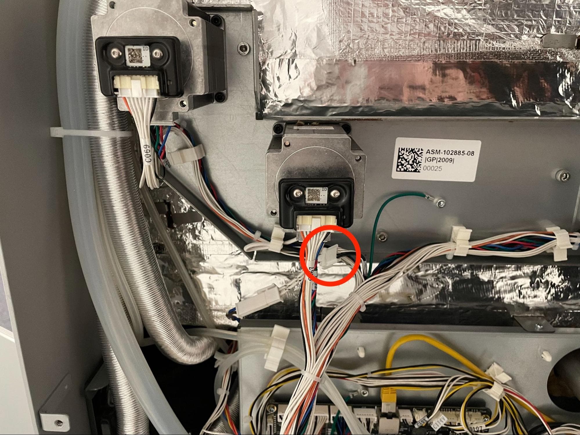
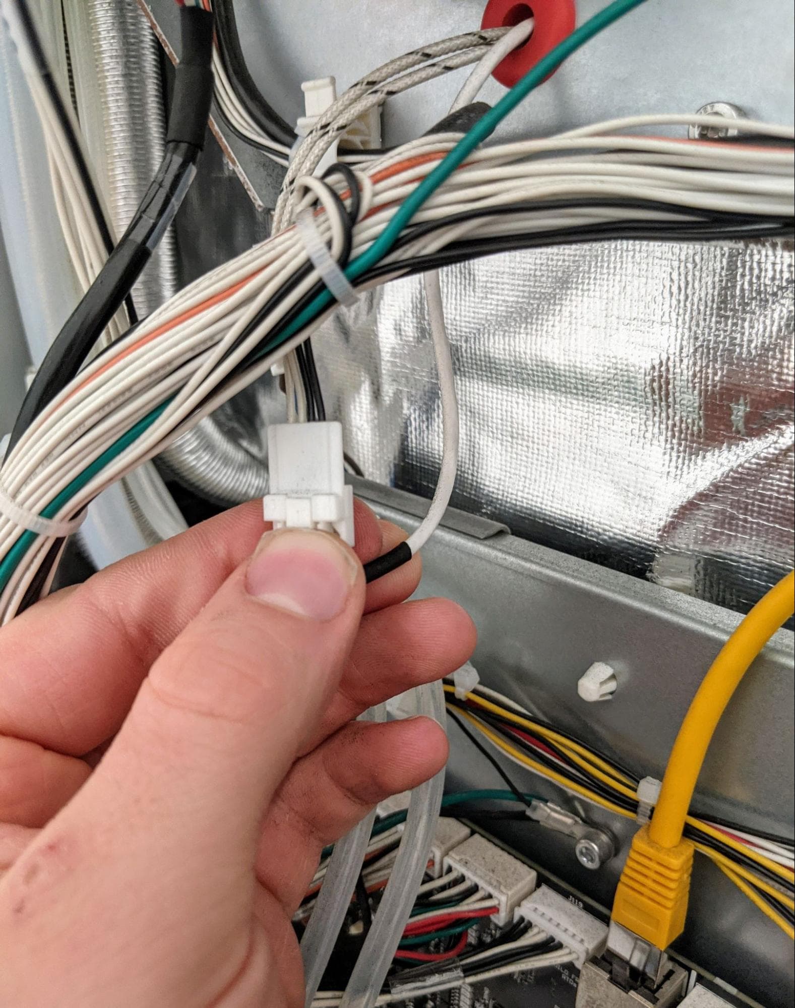
Locate the connector on the hopper side of the printer labeled C012. Disconnect the connector.

Step 2: Remove the hopper trough RTD connector

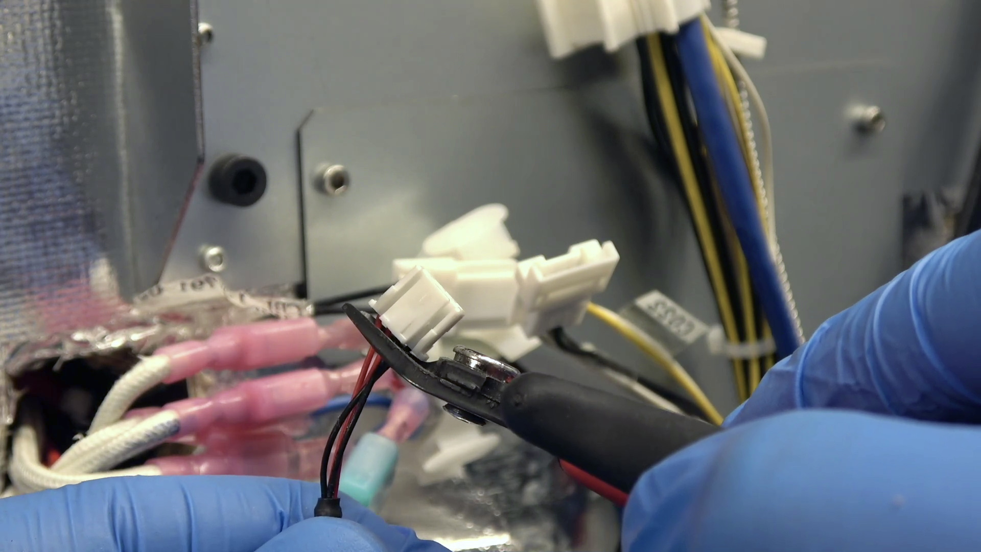
Use a pair of flush cutters to cut the connector off of the original RTD cable.

Remove the original RTD

Notice:

Make sure to cut the connector off of the RTD cable and not the extension cable that it attaches to.

Step 3: Locate the hopper trough RTD

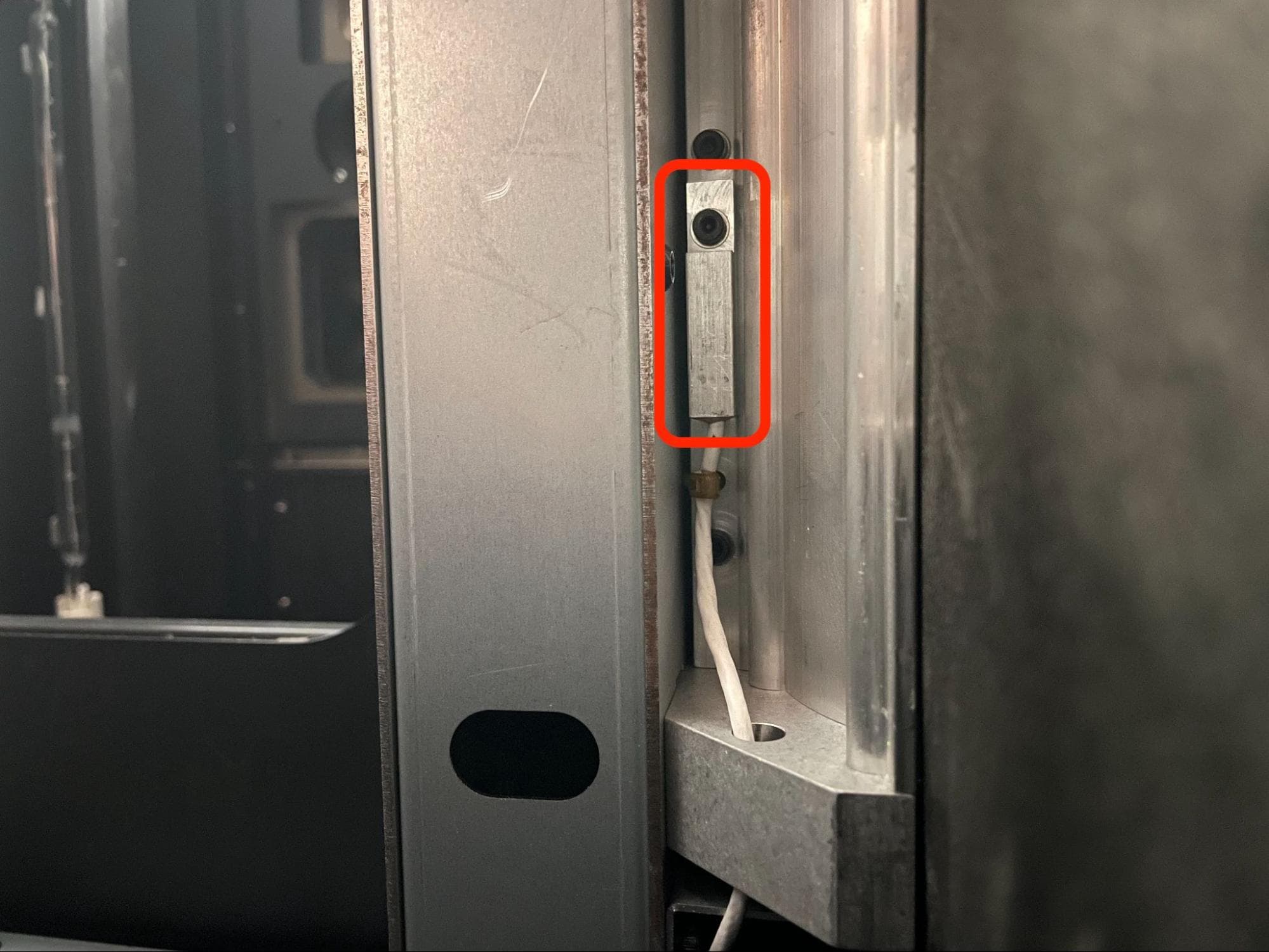
Open the filter cabinet door, then manually open the print enclosure door by pulling the blue release handle. Locate the hopper trough RTD, positioned on the inner right-hand wall of the print enclosure underneath the hopper-side flipper trough.

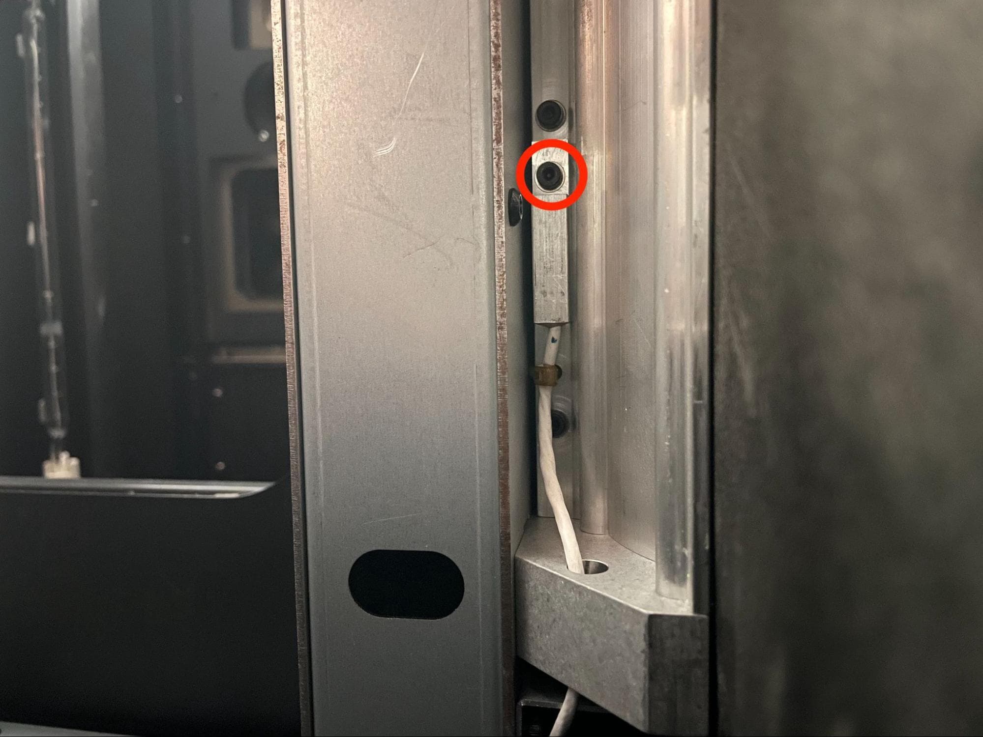
Step 4: Remove the hopper trough RTD retention screw

Using a 2.5 mm hex driver, loosen and remove the 22 mm M3 socket head screw that secures the RTD to the trough. Set the screw aside.

Remove the original RTD

Step 5: Remove the hopper trough RTD

Remove the original RTD

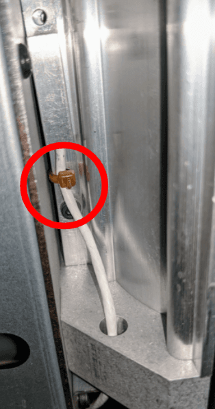
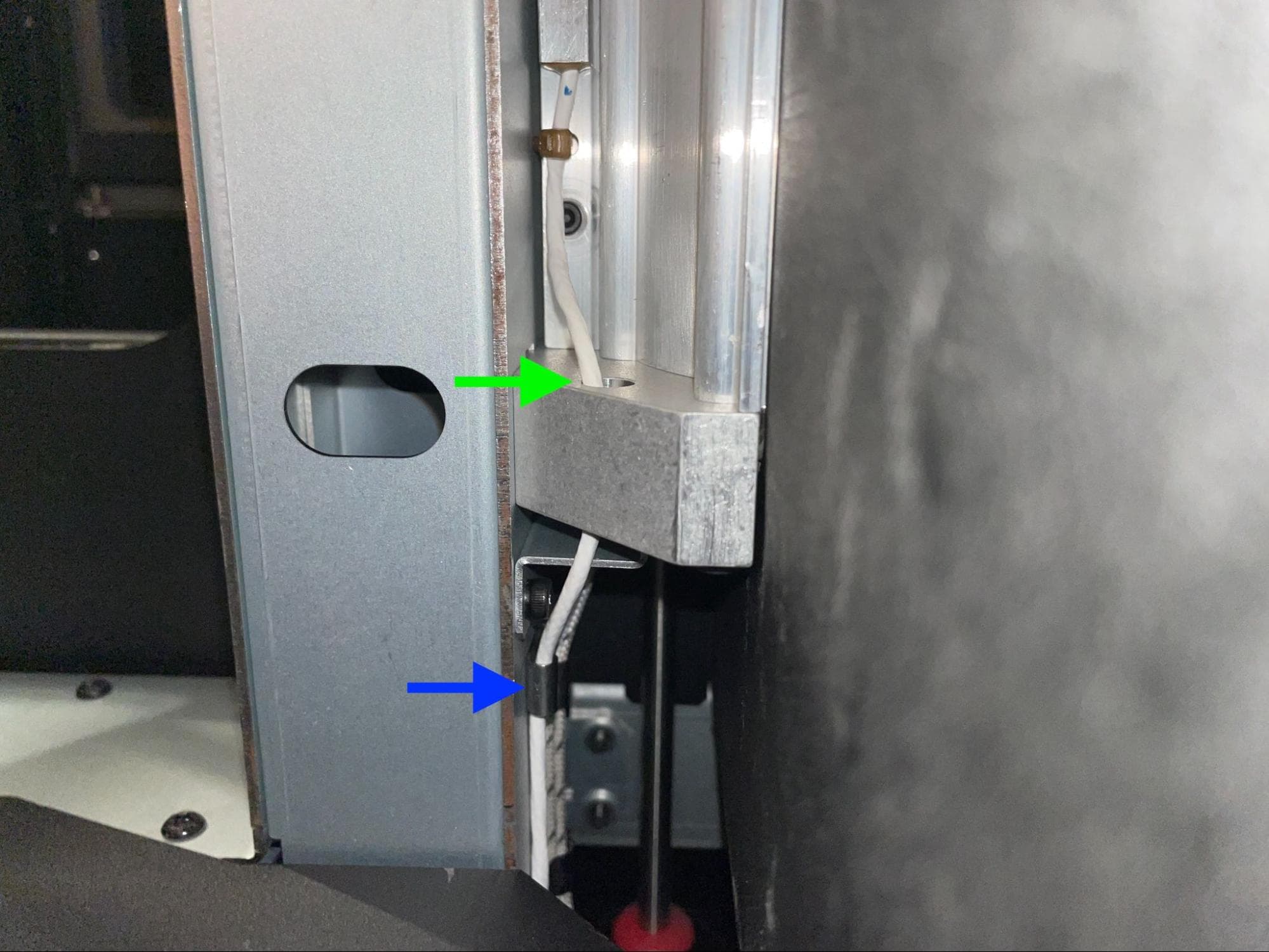
Use a pair of flush cutters to cut the zip tie securing the RTD cable to the trough. Begin pulling the original RTD cable into the print enclosure so it clears the red silicone grommet, the two metal retention clips behind the trough, and the through-hole in the trough. Once the cable is free, remove the original RTD from the printer and set it aside for disposal with electronic waste.

Installing the replacement hopper trough RTD

Overview: Mount, secure, and plug in the replacement hopper trough RTD.

Step 1: Prepare the hopper trough RTD for installation

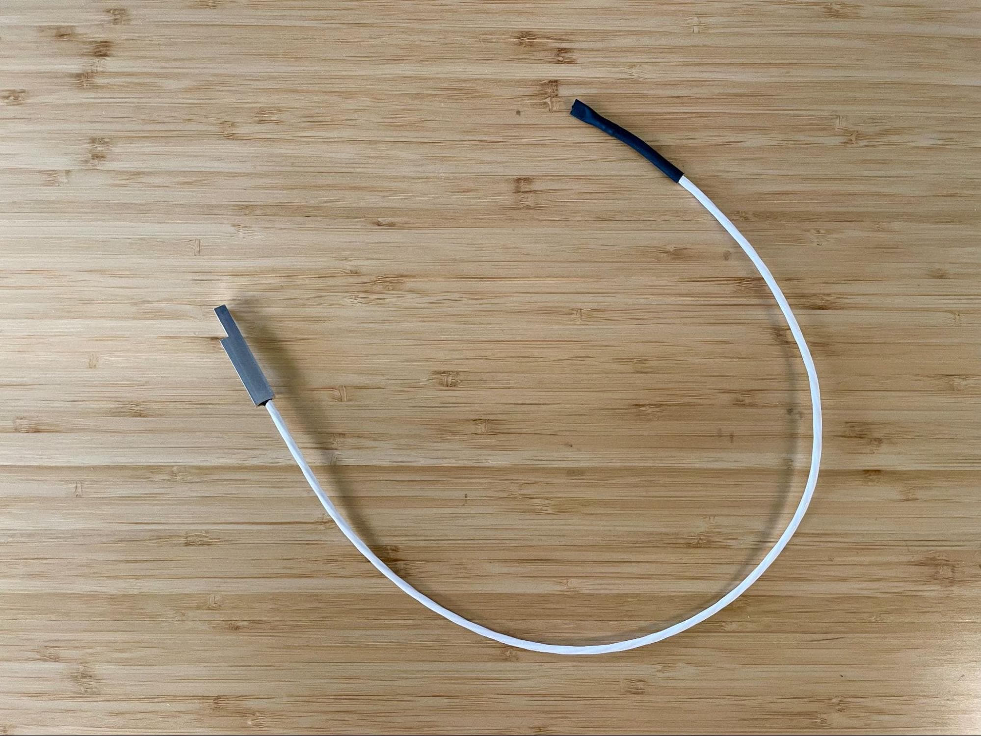
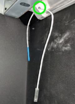
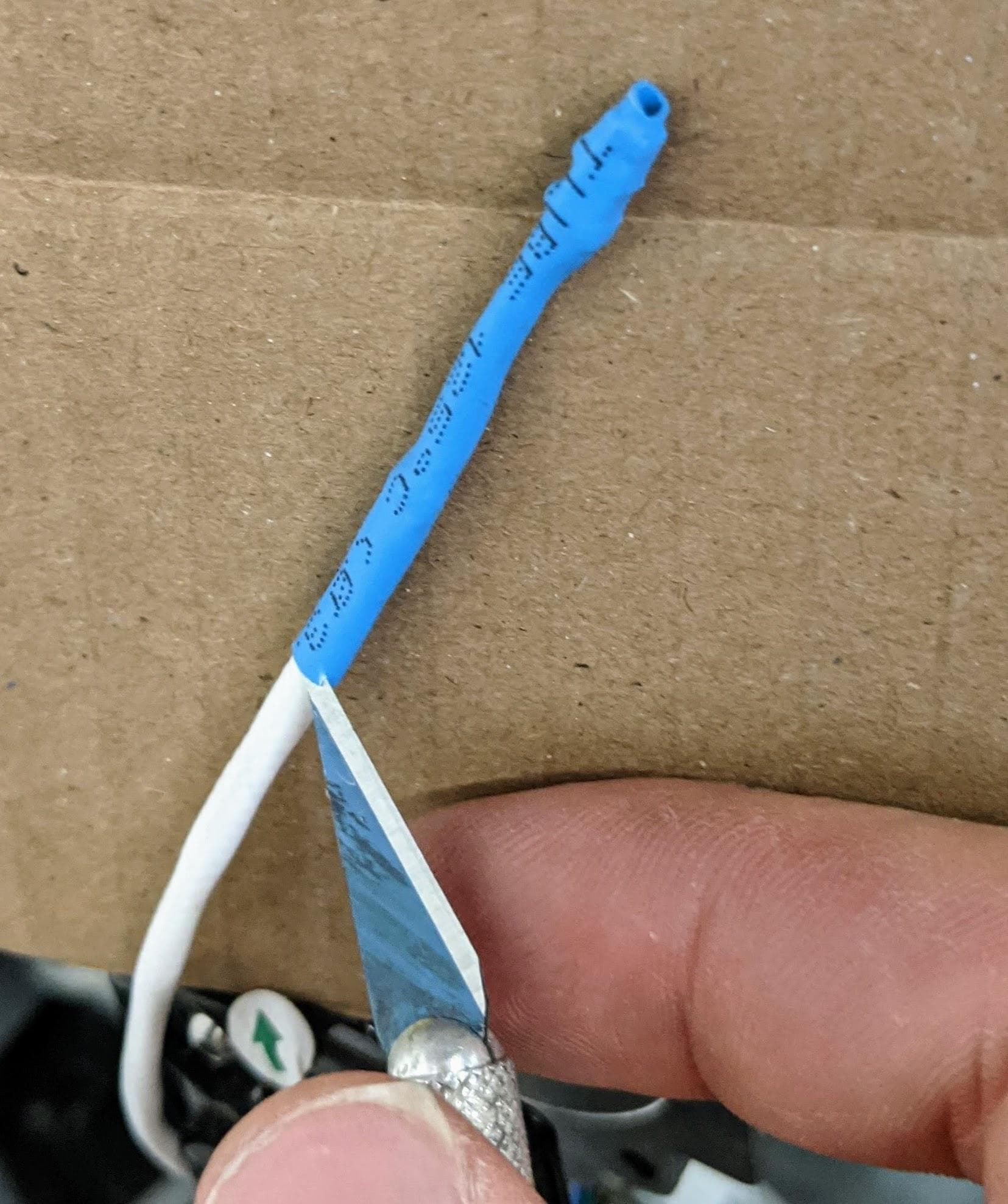
Unbox the replacement hopper trough RTD. Apply a piece of heat shrink tubing or tape to the end of the wires as shown. This makes it easier to feed the wires through the grommets without damaging them.

Install the new RTD

Step 2: Begin routing the hopper trough RTD cable

Install the new RTD
Install the new RTD

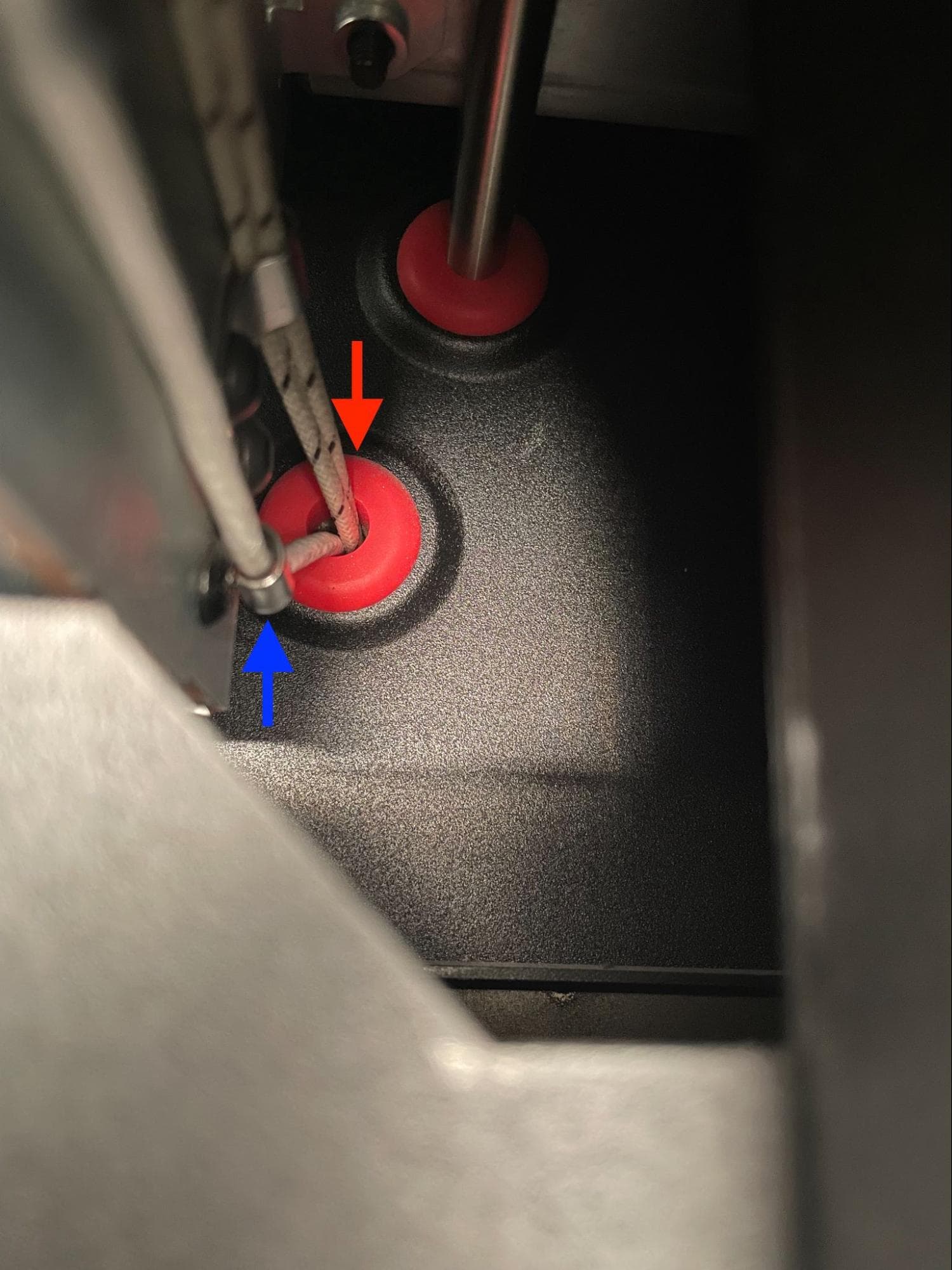
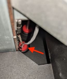
From inside the print enclosure, route the sheathed end of the new RTD cable through the trough through-hole, then the red silicone grommet. Do not feed the new RTD cable into the two metal retention clips identified previously.

Step 3: Continue routing the hopper trough RTD cable

Install the new RTD - View 1
Install the new RTD - View 2

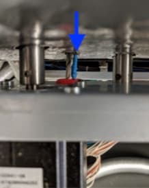
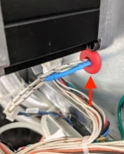
From the back of the printer, locate the new RTD cable sticking out of the insulation panel. Route the cable through the red silicone grommet immediately below the hopper flipper motor.

Step 4: Mount and secure the hopper trough RTD

Inside the print enclosure, align the screw hole in the hopper trough RTD with the corresponding screw hole in the bottom of the trough. Thread the 22 mm M3 socket heat screw into the screw hole, then use a 2.5 mm hex driver tighten until snug.

Install the new RTD - Mounting the RTD

Step 5: Expose the heater trough RTD wires

Exposing the heater trough RTD wires - View 1
Exposing the heater trough RTD wires - View 2

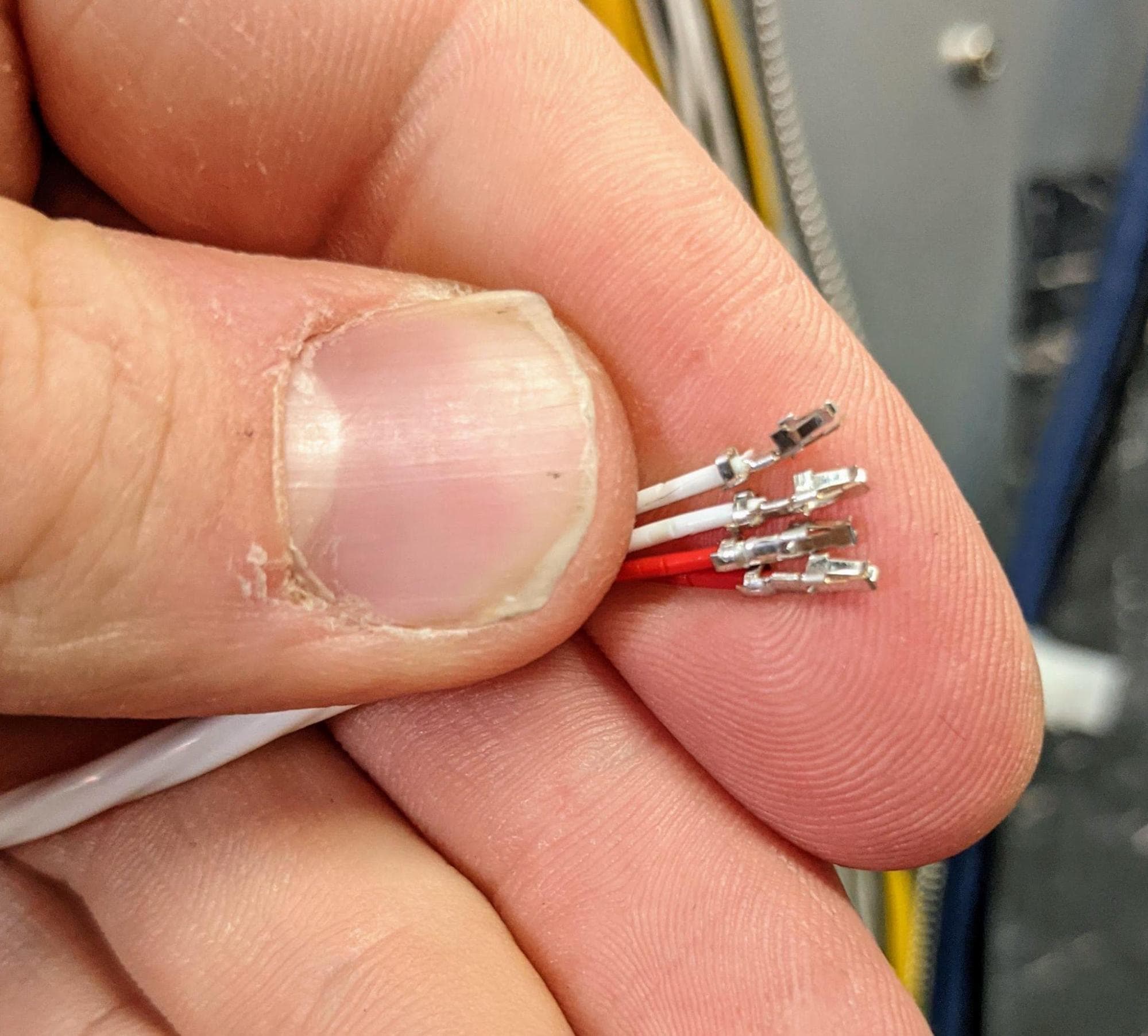
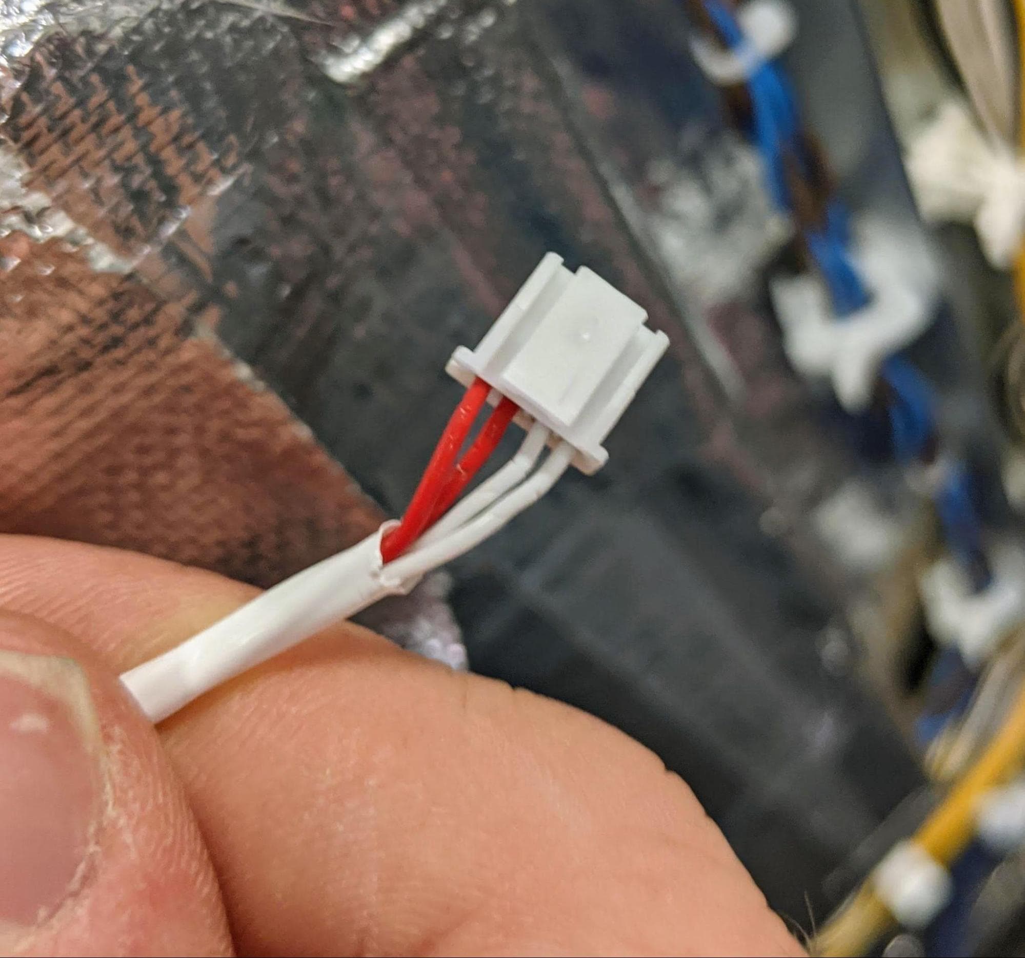
Carefully remove the heat shrink tubing or tape from the end of the wires and expose the contacts. If the insulation on any of the individual wires is broken and the conductor is exposed, the RTD cannot be used.

Step 6: Reconnect the hopper trough RTD connector

Install the new RTD - Connector Diagram 1
Install the new RTD - Connector Diagram 2
Install the new RTD - Wire Detail 1
Install the new RTD - Wire Detail 2

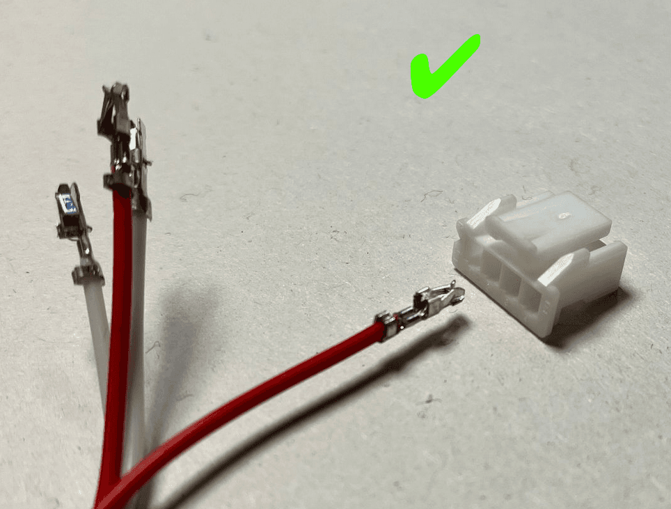
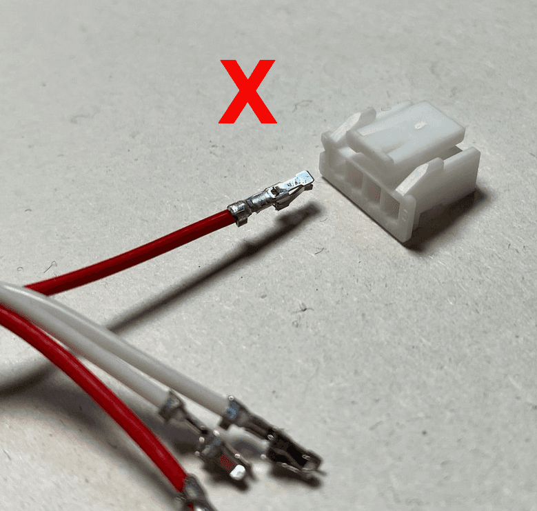
Slide the crimped connectors into the new connector. Follow pin order shown here. Reconnect the hopper trough RTD to its extension cable, labeled C012.

Reinstalling the rear panels

Overview: After installing the replacement hopper trough RTD, reinstall and secure the rear panels.

Step 1: Align the upper rear panel with the printer

Lift the upper rear panel and align it with the four screw holes on the top of the printer.

Step 2: Secure the upper rear panel top screws

Thread the four 6.0 mm screws into each of the screw holes on the top of the printer. Using a 2.5 mm hex driver, tighten the screws until finger tight. You may need to adjust the exhaust duct to correctly position the upper rear panel.

Step 1: Align the upper rear panel with the printer

Step 3: Secure the buffer side panel screws

Thread the two 6 mm screws into the screw holes on the buffer side and the two 6 mm screws into the screw holes on the hopper side. Using a 2.5 mm hex driver, tighten the screws until snug.

Step 3: Secure the buffer side panel screws

Step 4: Secure the hopper side panel screws

Thread the two 6mm screws into the holes on the hopper side. Using a 2.5 mm hex driver, tighten the screws until snug.

Step 4: Secure the hopper side panel screws

Step 5: Secure the upper rear panel grounding screws

The two black upper rear panel screws are circled in red. The two chrome upper rear panel grounding screws are circled in blue.

Thread the panel screws into the indicated screw holes on the upper rear panel. Refer to the image for the correct locations of the black and chrome screws. Using a 2.5 mm hex driver, screw in the two black panel screws and two chrome grounding screws securing the upper rear panel to the printer.

Step 5: Secure the upper rear panel grounding screws

Notice:

The placement of the chrome screws is critical to the printer's electrical grounding. Incorrect placement may lead to printer damage.

Step 6: Slide the exhaust duct into position

Step 6: Slide the exhaust duct into position - View 2

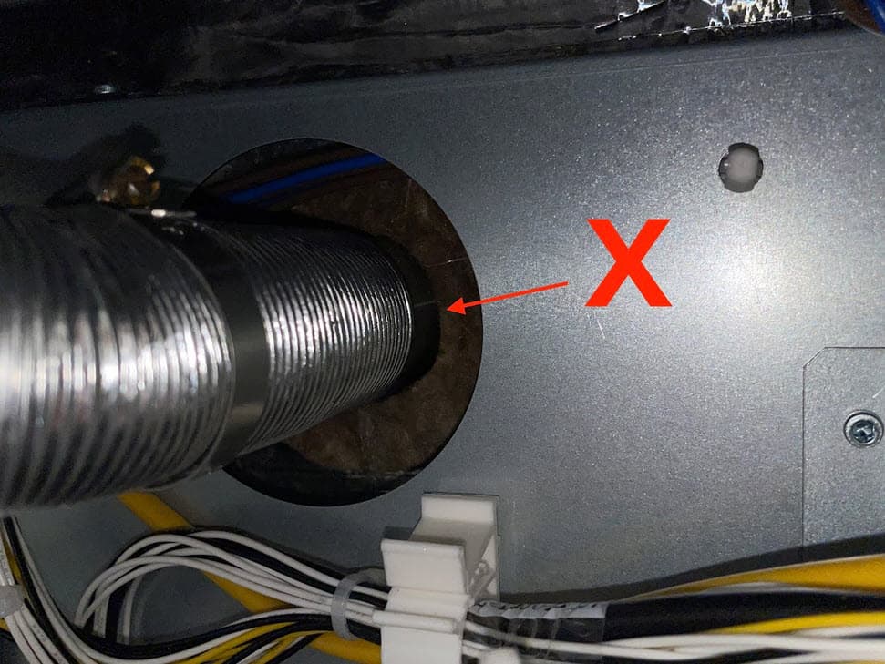
Slide the end of the exhaust duct with the ring clamp back onto the exhaust pipe. Ensure the exhaust duct presses against the insulation panel.

Step 7: Tighten the exhaust duct ring clamp

Using a 6.5 mm flathead screwdriver, tighten the ring clamp until finger tight.

Step 8: Secure the exhaust inlet screws

Open the filter cabinet door on the printer. Thread the four 8.0 mm screws into the screw holes. Using a 2.0 mm hex driver, screw in the four exhaust duct screws until finger tight.

Step 9: Check the exhaust duct seal

To ensure there is no gap between the exhaust duct’s mounting plate and the filter cabinet housing, shine a flashlight or other light source around the exhaust inlet inside the filter cabinet. If any light is visible behind the filter cabinet, the duct is not properly sealed. If necessary, use a 2.0 mm hex driver to tighten the exhaust duct screws. Close the filter cabinet door when finished.


Step 8: Secure the exhaust inlet screws

Step 10: Secure the lower rear panel grounding screws

The six black lower rear panel screws are circled in red. The four chrome lower rear panel grounding screws are circled in blue.

Thread the panel screws into the indicated screw holes on the lower rear panel. Refer to the image for the correct locations of the black and chrome screws. Using a 2.5 mm hex driver, screw in the six black panel screws and four chrome panel grounding screws securing the lower rear panel to the printer.

Step 1: Remove the lower rear panel screws

Notice:

The placement of the chrome screws is critical to the printer's electrical grounding. Incorrect placement may lead to printer damage.

Step 11: Reinstall the Wi-Fi antenna (optional)

Screw the Wi-Fi antenna onto the jack on the back of the unit.

Finalizing the repair

Step 1: Power on the printer

Connect the power cable to the printer and the power supply. The printer initializes.

Step 2: Test the repair

Start a print. Monitor the printer to ensure that the print proceeds normally. Contact Formlabs Support or your certified service provider to share the results of the procedure.