WHITE PAPER
Formlabs Logo

Replacing the Fuse Sift Z-drive assembly

Replacing the Fuse Sift Z-drive assembly

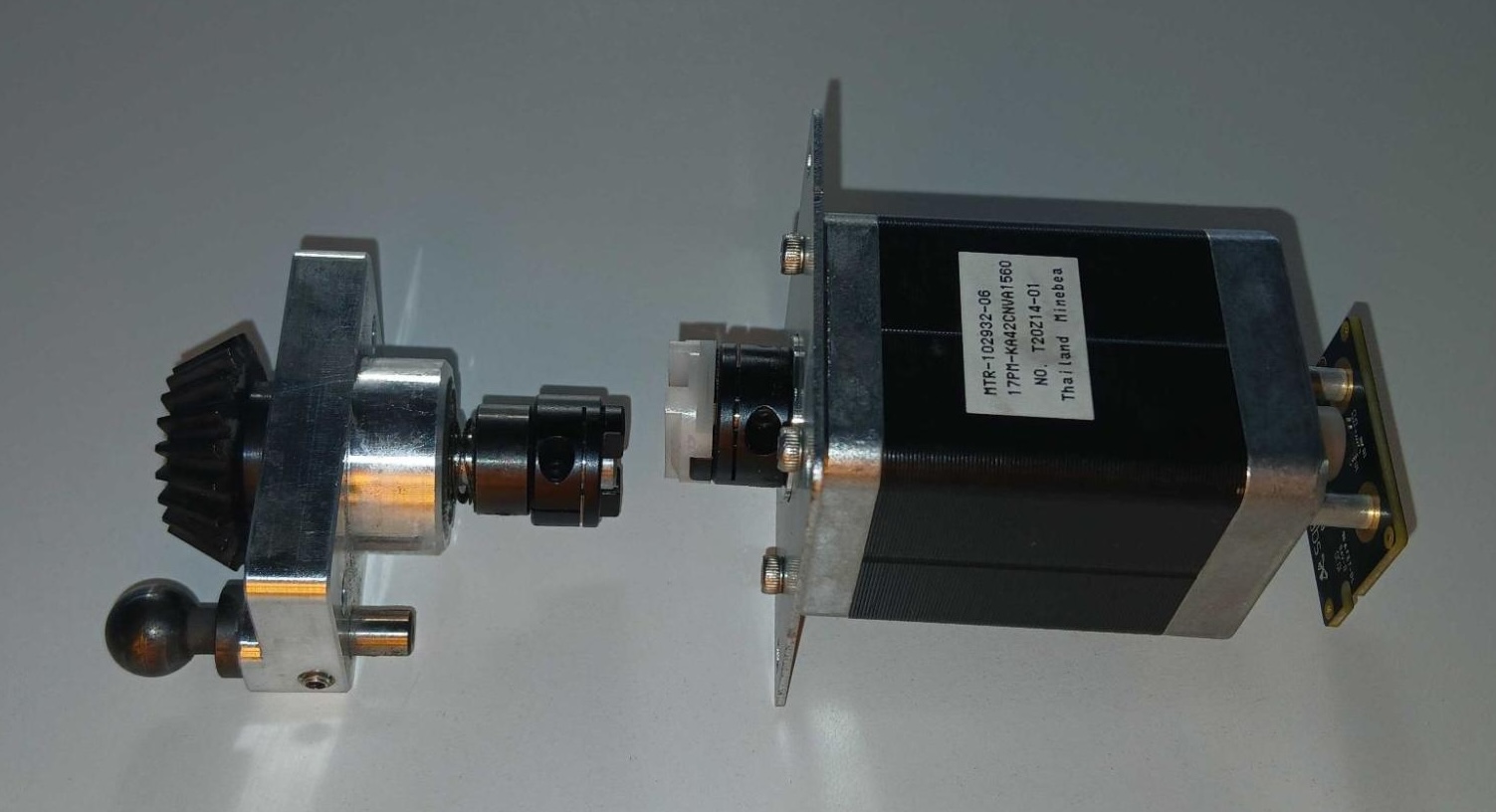
The Fuse Sift uses a motor and bevel gear, collectively called the Z-drive assembly, to move the build chamber print bed up and down. A malfunctioning Z-drive assembly prevents the Fuse Sift from controlling the print bed, keeping you from unpacking your prints.

Use this guide to replace the Fuse Sift Z-drive assembly.

Fuse Sift Z-drive assembly

Required Supplies:

Formlabs:

  • Fuse Sift Z-drive assembly (RP-SFT-ZDR-01)

Third-party:

  • 3.0 mm hex driver (flat-end)
  • 2.5 mm hex driver (flat-end)
  • Loctite 222 or equivalent threadlocker
  • Appropriate personal protective equipment for the powder in use, as defined in the safety data sheet (SDS)
Estimated time: 30–45 minutes

Preparing the workspace

Overview: Prepare the Fuse Sift and your workspace for replacing the Z-drive assembly.

Step 1: Remove and store printed parts

The Fuse Sift hood will be open during portions of this procedure. Remove any printed parts from the Fuse Sift workspace to prevent them from being damaged inadvertently.

Step 2: Clean the workspace

Using the vacuum attached to your Fuse Sift, clean the workspace. Vacuum any loose powder inside the workspace, under the hood, on the print bed and the surrounding port, and on the vent filter.

Warning:

Use appropriate personal protective equipment when handling loose or unsintered powder. Refer to the support article Safety with Formlabs SLS products or your powder’s safety data sheet (SDS) for more information.

Removing the rear enclosure panel

Overview: Remove the rear enclosure panel to better access the cartridge drawer components.

Step 1: Unplug the Fuse Sift

Power off the Fuse Sift, then unplug the power cable from the rear panel.

Danger:

Performing this procedure on the Fuse Sift while it is plugged in increases the risk of electric shock. After disconnecting the power from the Fuse Sift, wait at least five minutes before servicing.

Step 2: Unscrew the Wi-Fi antenna

Remove the Wi-Fi antenna, if present.

Step 3: Remove the rear enclosure panel

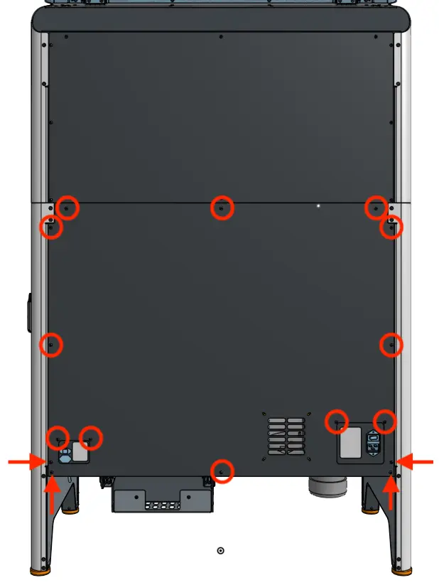
Use a 2.5 mm hex driver to remove the 16 black 8.0 mm M4 screws securing the rear panel to the Fuse Sift. Set the rear enclosure panel aside.

Fuse sift rear enclosure panel

Tip

Remove the top three screws last to prevent the panel from falling off.

Notice: 

The Fuse Sift contains sensitive electronic components. Ground yourself before touching any electronics in the device by using an antistatic wrist band.

Removing the Z-drive gear and motor

Overview: Remove the Z-drive assembly, starting with the bevel gear that the Fuse Sift uses to drive the print bed up and down.

Step 1: Locate the bevel gear

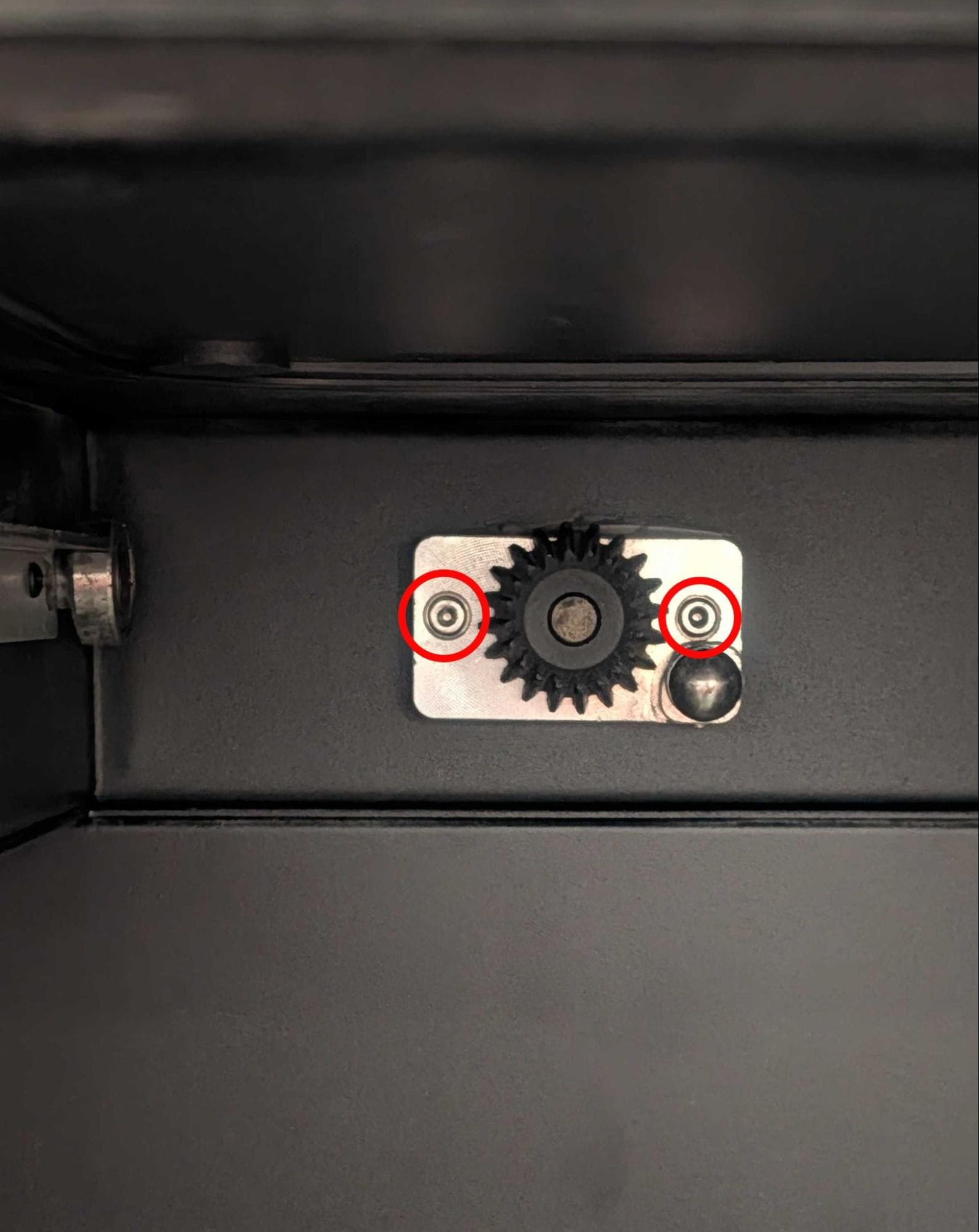
Locate the Z-drive gear, positioned at the back of the build chamber slot in the Fuse Sift.

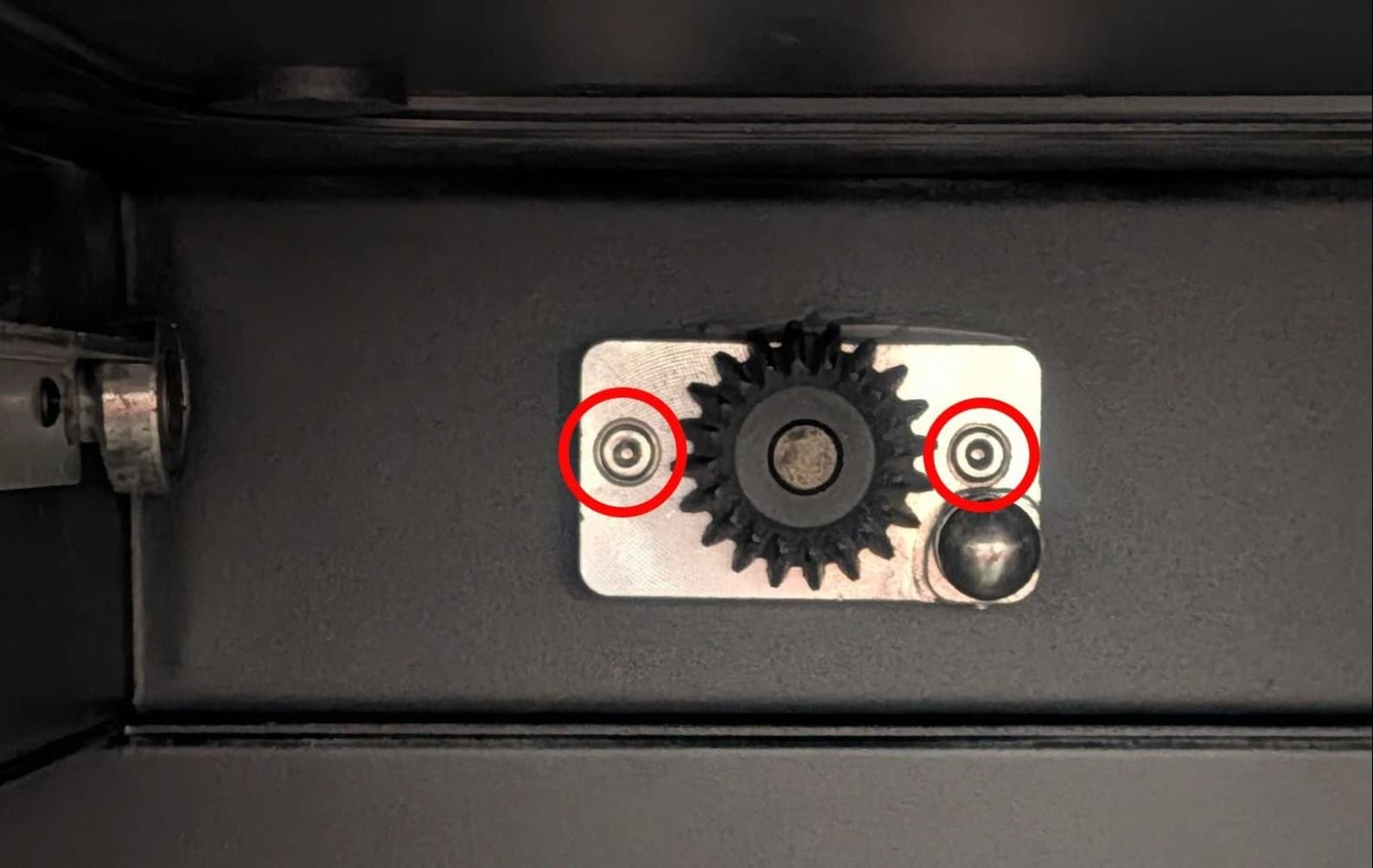
Step 2: Remove the Z-drive gear retention screws

Use a 3.0 mm hex driver to remove the two 8.0 mm M4 screws from the Z-drive.

Step 3: Remove the Z-drive gear from the Fuse Sift

Pull the Z-drive gear forward and out of the Fuse Sift. Set it aside for disposal.

Remove the Coupler Assembly

Step 4: Locate the Z-drive motor

Go to the back of the machine and locate the Z-drive motor, positioned opposite where the Z-drive gear was.

Step 5: Unplug the Z-drive motor cables

Unplug the encoder and power cables from the Z-drive motor. The encoder tab is held in place by a tab. Press on the tab to release the cable, then pull down on the connector to unplug it.

Remove the Coupler Assembly

Step 6: Remove the Z-drive motor retention screws

Use a 2.5 mm hex driver to remove the four 8 mm button top screws securing the Z-drive motor to the Fuse Sift. Do not remove the single screw near the lower-left corner of the motor.

Step 7: Remove the Z-drive motor from the Fuse Sift

Remove the Z-drive motor and set aside for disposal.

Remove the Coupler Assembly

Installing the new Z-drive assembly

Overview: Mount and secure the replacement Z-drive gear and motor.

Step 1: Mount the Z-drive gear

Orient the replacement Z-drive with the gear facing you and the ball at the lower-right corner. Insert the Z-drive coupler into the hole at the back of the build chamber slot. Ensure that the screw holes in the Z-drive align with the corresponding screw holes in the Fuse Sift.

Step 2: Secure the Z-drive gear

Place a small amount of threadlocker on the two 8.0 mm M4 screws that secured the original Z-drive to the Fuse Sift. Thread one screw into both of the two screw holes. Use a 3 mm hex driver to tighten until snug.

Install the new Z-drive and motor

Step 3: Mount the Z-drive motor

Orient the Z-drive motor with the cable connectors facing down. Align the coupler on the motor with the corresponding coupler on the Z-drive. Insert the Z-drive motor coupler into the hole behind the build chamber slot. Ensure that the screw holes in the Z-drive motor align with the corresponding screw holes in the Fuse Sift. Turn the bevel gear or motor coupling as necessary until the motor sits flush against the Fuse Sift..

Step 4: Secure the Z-drive motor

Place a small amount of threadlocker on the four 8.0 mm M4 button top screws that secured the original Z-drive motor to the Fuse Sift. Thread one screw into each of the four screw holes. Use a 2.5 mm hex driver to tighten until snug.

Step 5: Connect the Z-drive motor cables

Reconnect the motor power and encoder cables. The cables only fit into the connectors on the motor in the correct orientation.

Install the new Z-drive and motor

Testing the replacement Z-drive assembly

Overview: Test the replacement Z-drive assembly before reinstalling the rear panel.

Step 1: Power on the Fuse Sift

Reconnect the Fuse Sift to its power source. Flip the power switch to the ON position.

Danger:

Do not touch any exposed components within the Fuse Sift while it is connected to power.

Step 2: Test a build chamber

Insert a build chamber into the Fuse Sift. Test raising and lowering the build chamber using the Fuse Sift control panel.

Step 3: Adjust the Z-drive (optional)

If needed, adjust the Z-drive gear or motor. Be sure to power off the Fuse Sift and disconnect it from power before making any further adjustments.

Reinstalling the rear enclosure panel

Overview: Mount and secure the rear enclosure panel after installing the new display assembly and cable.

Step 1: Power off the Fuse Sift

Power off the Fuse Sift and disconnect it from power.

Step 2: Prepare the rear panel retention screws

Apply a small amount of Loctite 243 or other similar threadlocker to each of the 16 black 8.0 mm M4 button screws that secure the rear panel to the Fuse Sift.

Step 3: Mount the rear panel

Mount the rear panel onto the Fuse Sift.

Step 4: Secure the rear panel

Thread one 8.0 mm M4 button screw into each of the 16 screw holes in the rear panel. Use a 2.5 mm hex driver to tighten until snug.


Fuse sift rear enclosure panel

Tip:

Start with the top three screws to hold the panel in place while you thread and tighten the remaining screws.

Finalizing the repair

Overview: After installing the new Z-drive assembly, continue using the Fuse Sift to depowder your parts and fill powder cartridges.

Step 1: Power on the Fuse Sift

Reconnect the Fuse Sift to its power source. Flip the power switch to the ON position.

Step 2: Insert a build chamber and retrieve printed parts

Insert a build chamber into the Fuse Sift and depowder your parts as normal.