WHITE PAPER
Formlabs Logo

Removing Wi-Fi hardware (Fuse 1 generation)

Removing Wi-Fi hardware (Fuse 1 generation)

Fuse 1 generation printers have Wi-Fi functionality for receiving print jobs and firmware updates and uploading log files. Wi-Fi can be turned off via the printer's touchscreen, but depending on your organization's security requirements, you may need to physically remove the Wi-Fi hardware before using the printer. This hardware includes a component on the system on a module (SOM) plugged into the motherboard as well as one or two Wi-Fi antennas plugged into the SOM.

Use this guide to remove all Wi-Fi hardware from a Fuse 1 generation printer.

Fuse 1 generation SOM

Required supplies:

Third-party:

  • 1.5 mm hex driver (flat-end)
  • 2.5 mm hex driver (flat-end)
  • 3 mm hex driver (must have a 90º head)
  • ESD-safe spudger (recommended) or ESD-safe tweezers
  • ESD-safe small plastic bag (optional)
  • Hot rework tweezers or other SMD soldering equipment
  • Antistatic wrist band
  • Safety glasses
  • Nonreactive nitrile gloves
  • 99% ethanol or 99% isopropyl alcohol
  • Microfiber cloth

Estimated time: 60–75 minutes

Danger:

Read and follow all safety instructions and warnings in the operator manual. Replacement with incorrect parts can lead to burns, shock, fire, or explosion. Dispose of all parts in accordance with local regulations.

Warning:

Do not perform this procedure if the printer was printing less than six hours prior. Failure to do so may result in serious burns. Allow the print enclosure to cool to room temperature before touching or inspecting any Fuse 1 components.

Preparing the workspace

Overview: Prepare the printer and a dust-free workspace for modifying the SOM.

Notice:

Fuse 1 generation printers contain sensitive electronic components. Ground yourself before touching any electronics in the printer by using a grounding strap or touching a grounded piece of metal.

Step 1: Prepare the workspace

Clear a workspace around your printer. Ensure that the workspace is well-ventilated and free of dust.

Step 2: Unplug the printer

Disconnect the power cable before continuing with maintenance. Do not perform maintenance on the printer while it is connected to power. Wait five minutes after disconnecting the printer from power before proceeding.

Danger:

Performing maintenance on the printer while it is plugged in increases the risk of electric shock. Never remove the back panel of the printer while the printer is plugged in. Never reconnect the printer to power while the back panel is uninstalled.

Removing the display assembly

Overview: Remove the display assembly to access the motherboard and SOM.

Step 1: Remove the display assembly

Follow the instructions for your printer type to uninstall the display assembly. Do not separate the motherboard from the display, but remember to unplug the Wi-Fi antenna cable(s) from the SOM.

Removing the original SOM

Overview: Uninstall the original SOM from the motherboard.

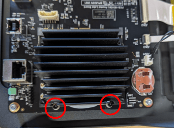
Step 1: Remove the SOM retention screws

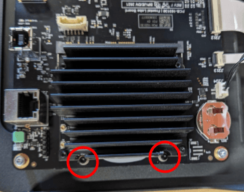
Using a 1.5 mm hex driver, loosen and remove the two 5 mm M2 socket head screws securing the SOM to the motherboard. Set the screws aside.

Remove the SOM

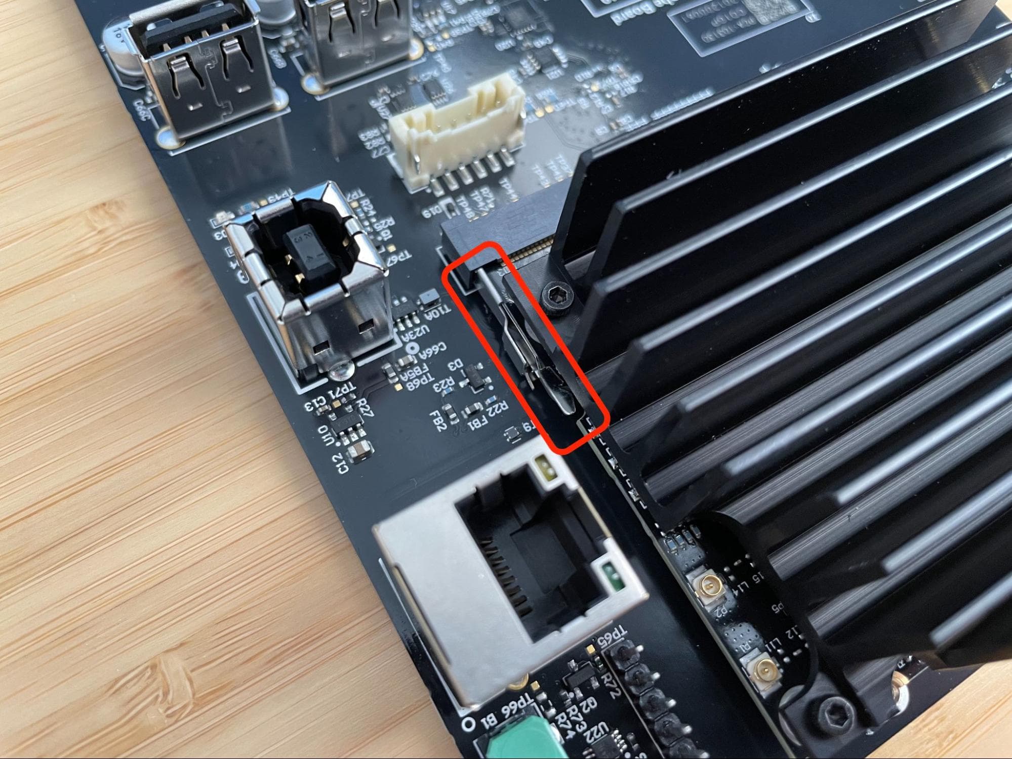
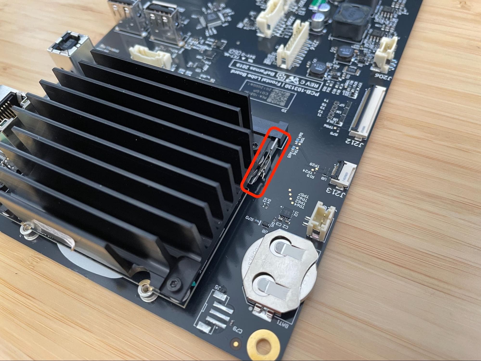
Step 2: Locate the SOM retention tabs

Remove the SOM
Remove the SOM

Locate the two retention tabs (one on each side) securing the SOM to the motherboard.

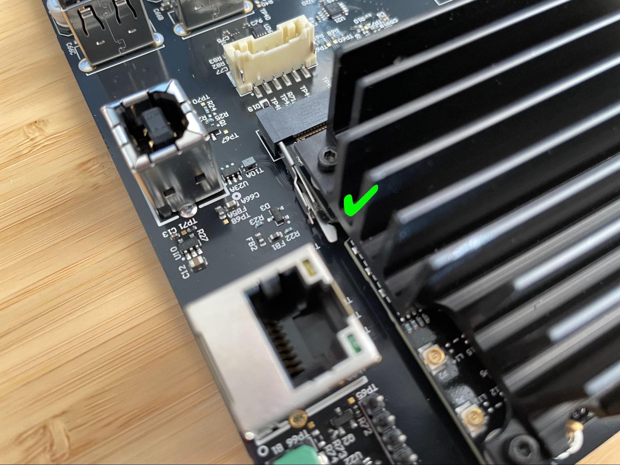
Step 3: Open the retention tabs

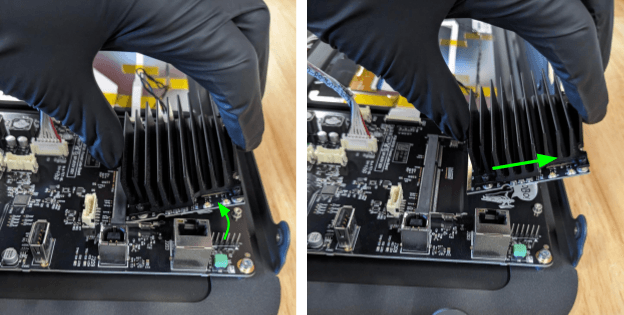
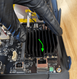
Use an ESD-safe spudger or a pair of ESD-safe tweezers to disengage the retention tabs by flexing them outwards slightly. The end of the SOM opposite the socket may lift up slightly.

Remove the SOM

Step 4: Remove the SOM

Gently grip the SOM by the heat sink, pivot it upwards at approximately a 30º angle, then pull it straight away from the motherboard.

Remove the SOM

Modifying the SOM

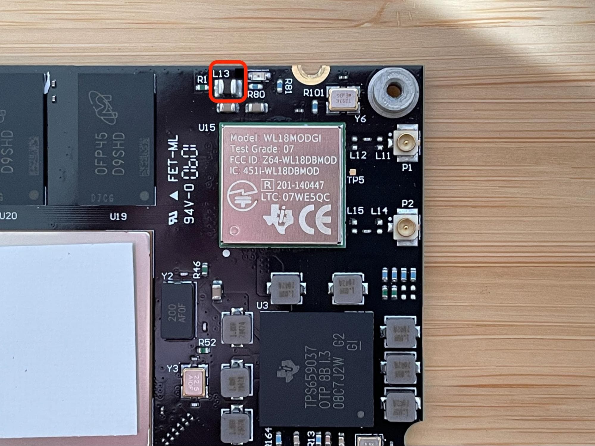
Overview: After removing the SOM from the printer, remove component L13.

Step 1: Prepare to modify the SOM

If you have not already, put on an antistatic wrist band and connect it to a known ground point. Do not connect the wristband any surfaces that are powder-coated or painted. Prepare a pair of hot rework tweezers or appropriate SMD soldering equipment, as well as any necessary personal protective equipment.

Step 2: Unscrew and remove the heatsink

Modifying the SOM
Modifying the SOM

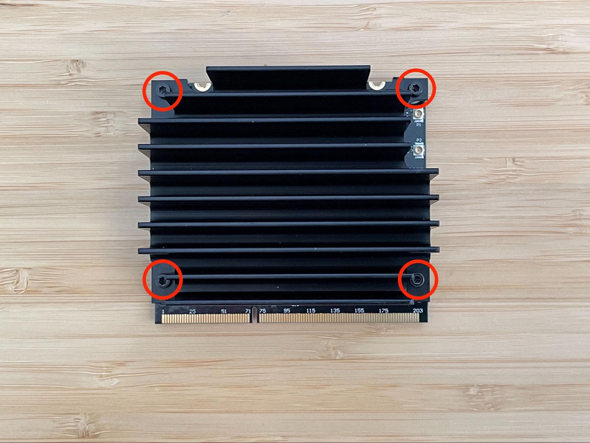
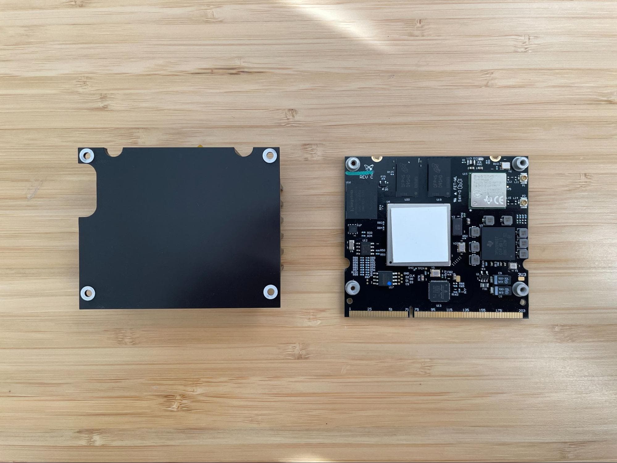
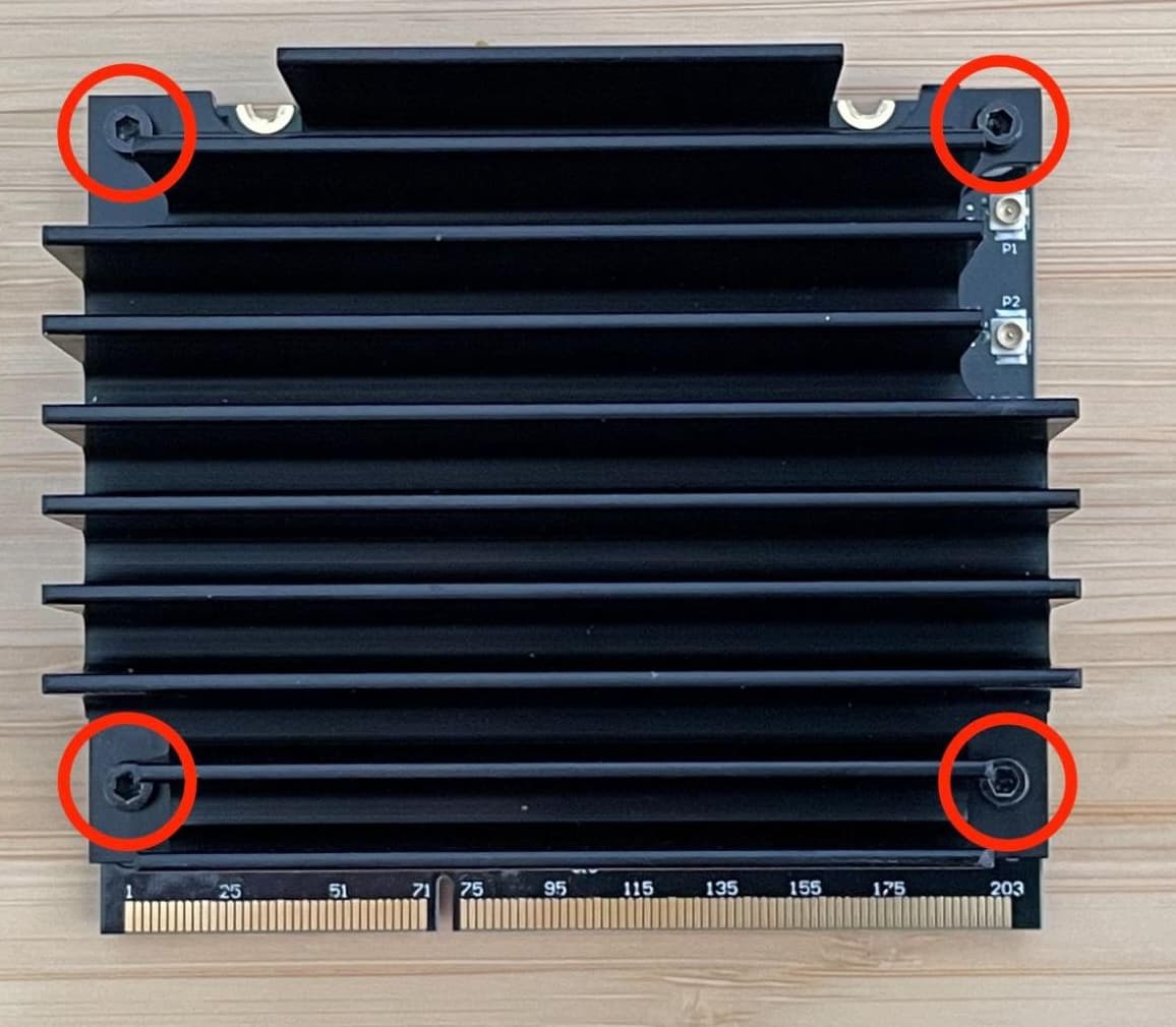
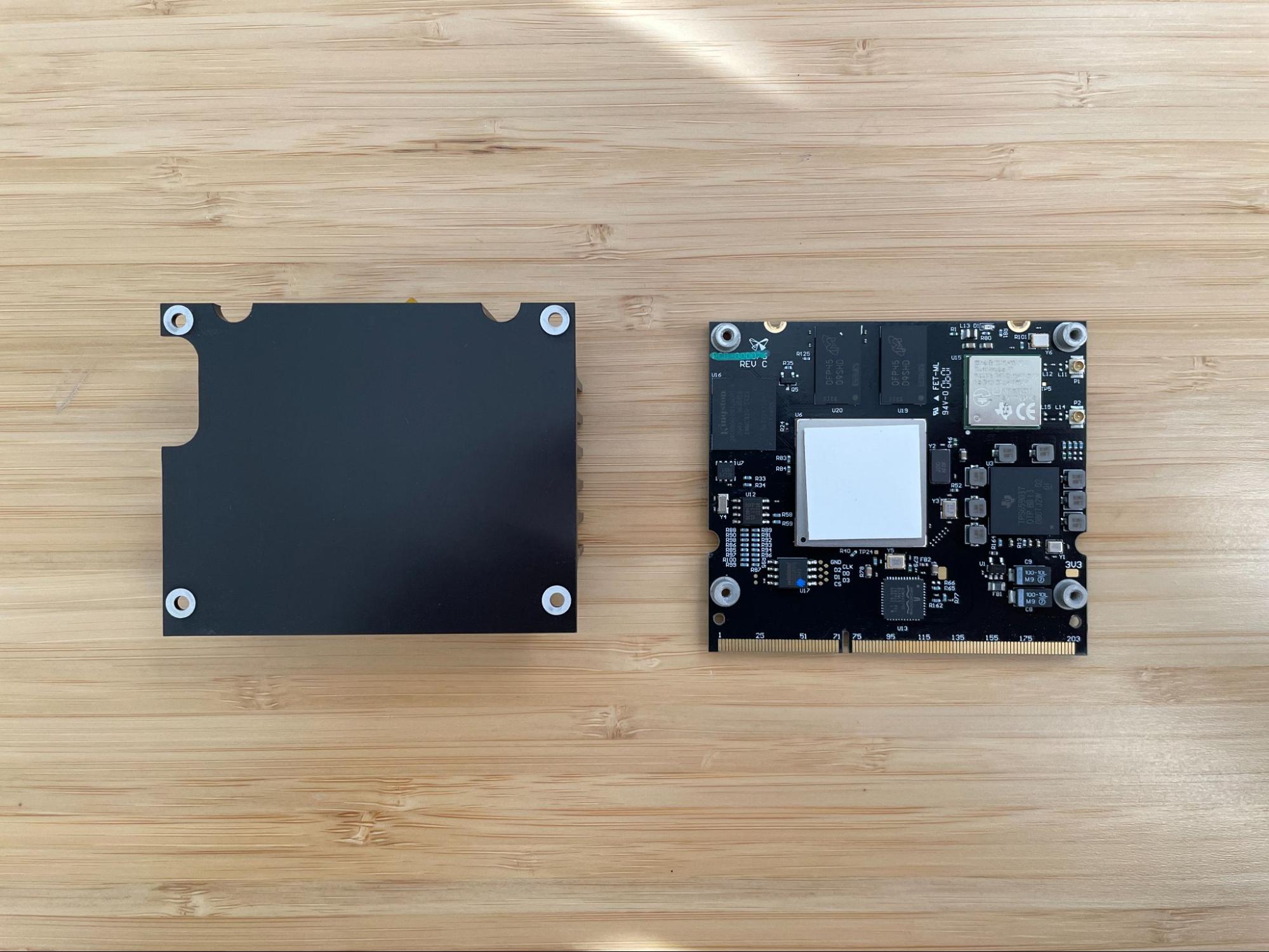
Using a 1.5 mm hex driver, unscrew and remove the four screws securing the heatsink to the SOM. Set the screws aside. Remove the heatsink and set it aside fins down.

Step 3: Remove component L13

Using hot tweezers or other appropriate SMD soldering equipment, remove component L13 from the SOM. If you plan to reverse this procedure in the future, save component L13 for later reuse in an ESD-safe bag.

Modifying the SOM

Step 4: Reinstall the heatsink

Modifying the SOM
Modifying the SOM

Put on a pair of clean, nonreactive nitrile gloves. Use a microfiber cloth wetted with a small amount of ethanol to wipe any contaminants off of the flat heatsink face.

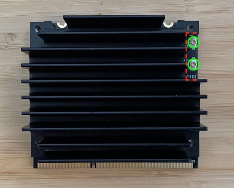
Reinstall the heatsink onto the SOM, making sure the thermal pad on the bottom of the heatsink covers the processor (the largest chip on the board, labeled U6). Ensure that the cutout on the edge of the heatsink allows access to the two Wi-Fi antenna ports and that the screw holes in the heatsink align with the holes in the SOM.

Insert one 3 mm M2 screw into each of the four screw holes in the heatsink. Using a 1.5 mm hex driver, tighten the four screws until finger tight. Do not overtighten.

Reinstalling the SOM

Overview: Insert the modified SOM into its slot on the motherboard and secure it in place.

Step 1: Insert the SOM into its socket

Install the replacement SOM

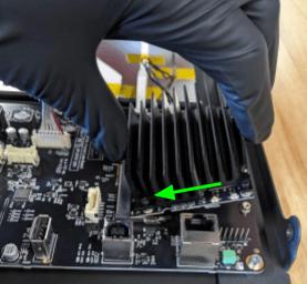
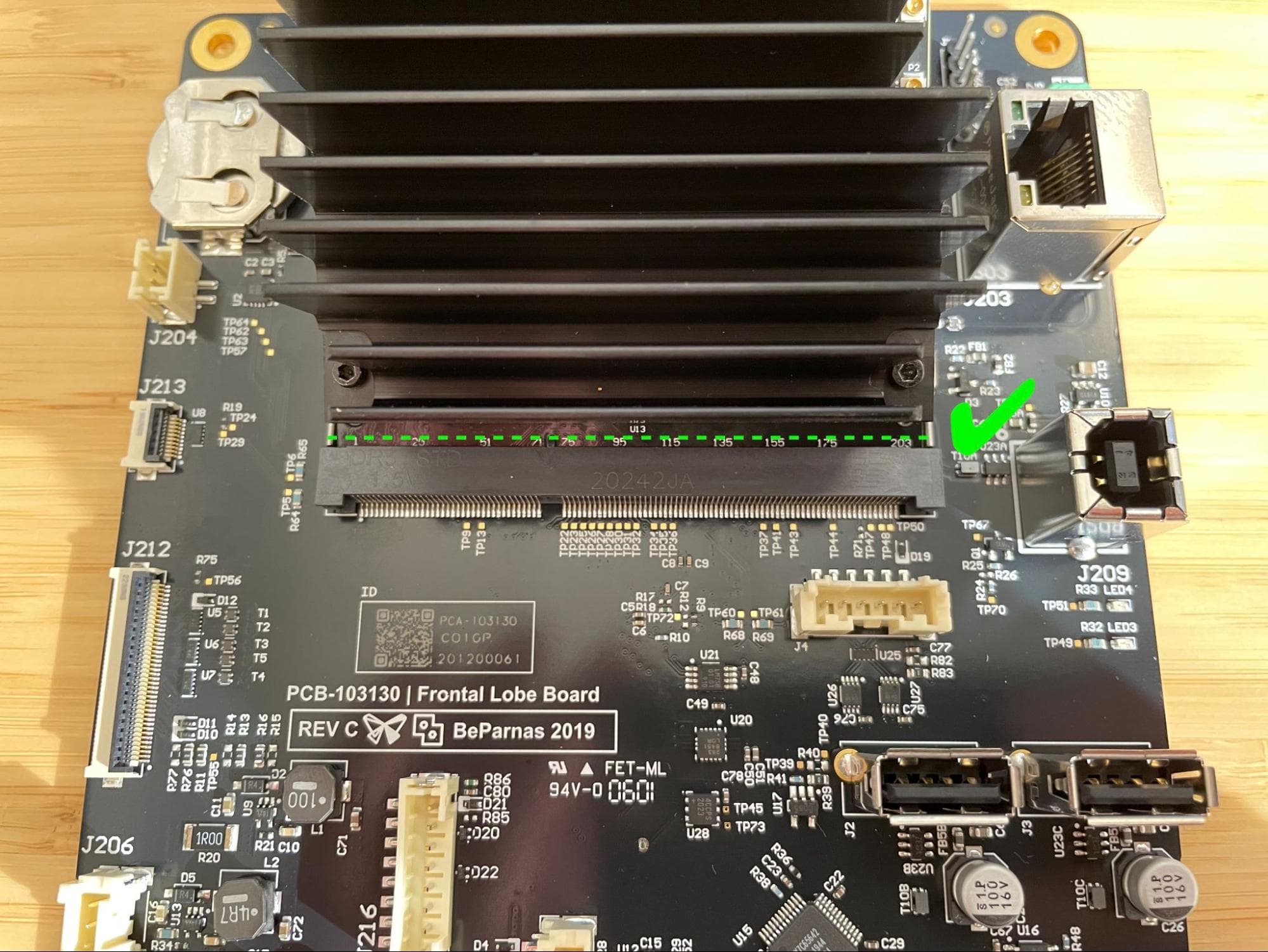
Pick up the SOM by the heatsink, then insert it into the socket on the motherboard at approximately a 30º angle. Gently push the SOM into the socket so that none of the gold pins on the SOM are visible.

Step 2: Secure the SOM with the retention tabs

Push the SOM down onto the motherboard until the retention tabs snap into place.

Install the replacement SOM

Step 3: Fully secure the SOM

Thread one 5.0 mm M2 screw into both of the two screw holes in the SOM. Using a 1.5 mm hex driver, tighten until finger-tight.

Install the replacement SOM

Reinstalling the display assembly

Overview: After reinstalling the SOM, reinstall the display assembly.

Step 1: Reinstall the display assembly

Follow the instructions for your printer type to reinstall the display assembly. Do not reattach the Wi-Fi antenna cable(s) to the SOM

Finalizing the repair

Overview: After installing the modified SOM, power on the printer and perform final checks.

Step 1: Power on the printer

Connect the power cable to the printer and the power supply. The printer initializes.

Step 2: Test the repair

Start a print. Monitor the printer to ensure that the print proceeds normally. Contact Formlabs Support or your certified service provider to share the results of the procedure.