WHITEPAPER
Formlabs Logo

Cleaning the air filters on a Fuse 1 generation printer

Cleaning the air filters on a Fuse 1 generation printer

Fuse 1 generation printers contain two filters: an intake filter and an exhaust filter. The intake filter keeps the air within the print enclosure free of contaminants that may adversely affect print quality. Both the filters and surrounding components should be cleaned to prevent print failures.

The rate of cleaning is dependent on the age of the filter:

  • The exhaust filter should be cleaned after every 30 hours of printing
  • The intake filter should be cleaned in cases of low pressure warnings
  • Purge the exhaust line after 500 hours of printing to remove blockages
  • Clean the exhaust fan when laurolactam buildup is visible
  • Replace old filters after 2400 hours of printing

Cleaning the air filter system on the Fuse 1 generation consists of four different tasks:

  1. Cleaning the exhaust filter
  2. Purging the exhaust line
  3. Cleaning the exhaust fan and exhaust tube
  4. Cleaning the intake filter (if needed or if intake pressure warnings appear)
Menschlicher Kopf (linkes Profil) mit einer Maske

Vorsicht:

Human head (left-hand profile) wearing a mask

Verwenden Sie niemals Druckluft, um das Druckgehäuse, die Konstruktionskammer oder andere Komponenten zu reinigen. Das Aufwirbeln von losen Partikeln erhöht das Risiko unbeabsichtigter Inhalation oder unbeabsichtigten Verschluckens.


Note:

Filter cleaning frequency and filter lifetimes are tracked and prompted automatically via the touchscreen. Follow the prompts on the touchscreen when cleaning filters in order to properly track frequency and prevent print failures.

The Fuse 1's touchscreen displays the 'Maintenance' screen and the 'Clean Air Filter' option is selected

Cleaning the exhaust filter

The exhaust filter is located behind a cabinet door on the right side of the printer. Clean the filter after 30 hours of printing.

To clean the exhaust filter:

  1. Tap Maintenance > Printer Checklist > Replace Air Filter on the printer’s touchscreen.
  2. Open the filter cabinet door on the right side of the printer. The exhaust filter is the large metal box on the right side. When the filter cabinet door is opened, the exhaust fan automatically turns off.
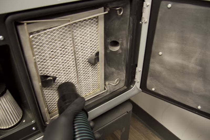
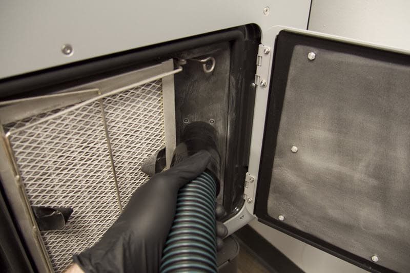
  3. Place the hose against the grate and slowly move the hose up and down until all powder is removed.
A vacuum hose is being brought to the grate of the exhaust filter

To check and clean laurolactam build up:

  1. Depress the retainer hook at the top of the exhaust filter and disengage it from the pin.
  2. Depress the retainer hook at the bottom of the exhaust filter and disengage it from the pin.
  3. Move the retainer out of the way, then remove the exhaust filter using the fabric pull tabs. Set the filter aside.
  4. Vacuum the recess behind the exhaust filter bay on the printer. If laurolactam has accumulated on the fan, it may be necessary to use a pipe cleaning brush or brush nozzle to remove the buildup.
  5. While the exhaust filter is removed from the printer, vacuum the back side of the filter. When you are done, reinstall the filter.
    1. Move the vacuum hose from left to right to clean powder and laurolactam from the back of the exhaust filter.
    2. Move the vacuum downward until ending at the bottom-right corner.
    3. Repeat until the entire filter is clean.
    4. Reinstall the exhaust filter with the black gasket facing away from you, then re-engage the retainer.
  6. Vacuum any powder on the filter cabinet door.
  7. Power off the vacuum and close the file cabinet door.
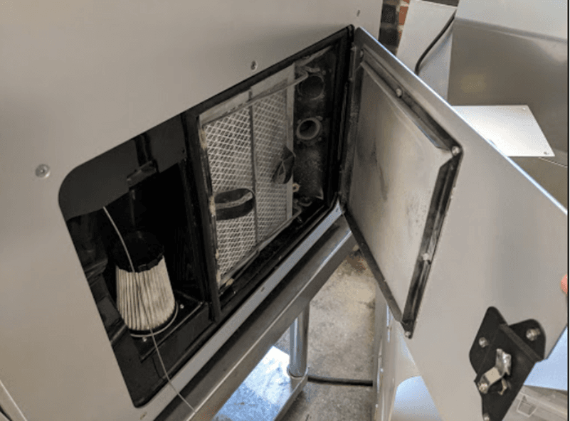
The cabinet door on the right side of the Fuse 1 is open to show the air filters

Purging the exhaust line

With typical use, marginal amounts of powder and laurolactam can accumulate in the exhaust line. It is important to periodically purge the exhaust line to maintain airflow out of the print enclosure.

Notice:

  • Before proceeding, ensure that the build chamber has fully cooled before removing it from the Fuse 1 generation printer.
  • Ensure that the print enclosure door is open before continuing. If the print enclosure door remains shut while you purge the exhaust line, powder may be drawn from the hopper into the print enclosure and cause the next print to fail.

To purge the exhaust line:

  1. Once the build chamber has fully cooled, remove it from the printer. Insert it into the Fuse Sift or set it aside on a clean surface.
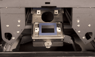
  2. Insert a clean optical cassette into the printer. This protects the optics from loose powder during cleaning.
Optical cassette inserted into a Fuse 1 printer
  1. Open the filter cabinet door on the right side of the printer. The exhaust line is housed in a component to the right of the exhaust fan. When the filter cabinet door is opened, the exhaust fan automatically turns off.
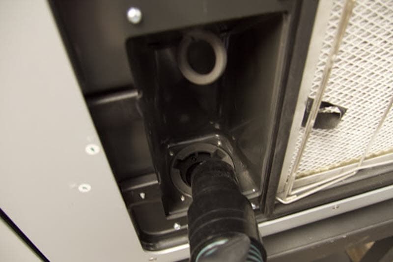
  2. The exhaust line is housed in a component to the right of the exhaust filter. There is one circular opening that must be purged to maintain consistent air flow.
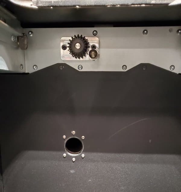
  3. Locate the circular inner exhaust line port, located on the rear wall of the print enclosure.
The inner exhaust port located inside the print enclosure
  1. Hold the vacuum hose up to the port for 60 seconds.
  2. Power off the vacuum and close the cabinet door.
Vacuuming the exhaust port in a Fuse 1 generation printer

Cleaning the exhaust fan and exhaust tube

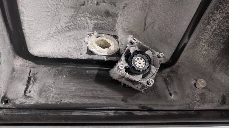
Laurolactam buildup on the exhaust fan and the lower exhaust tube (Fuse 1 only) prevents the print enclosure from reaching the correct pressure. If you see a Chamber Pressure Too High error (Fuse 1 only), remove this buildup so the printer can reach a low enough chamber pressure and pass preprint checks.

The exhaust filter and exhaust fan have been removed revealing a large laurolactam buildup blocking the exhaust tube

To clean the exhaust fan:

  1. Open the filter cabinet door on the right side of the printer. The exhaust fan and tube are located behind the exhaust filter on the right side. When the filter cabinet door is opened, the exhaust fan automatically turns off.
  2. Remove the exhaust filter.
    1. Depress the retainer hook at the top of the exhaust filter and disengage it from the pin.
    2. Depress the retainer hook at the bottom of the exhaust filter and disengage it from the pin.
    3. Move the retainer out of the way, then remove the exhaust filter using the fabric pull tabs. Set the filter aside.
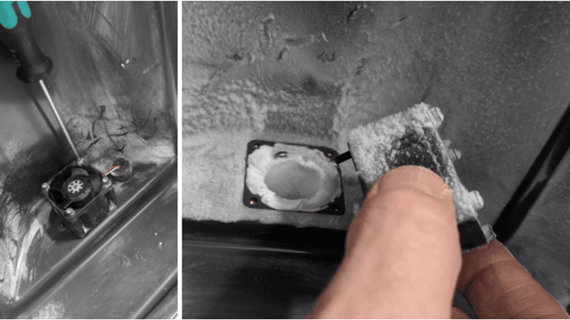
  3. Using the 2.5 mm hex screwdriver, remove the four screws that hold the exhaust fan to the filter cabinet.
Someone is unscrewing the exhaust fan and pulling it forward
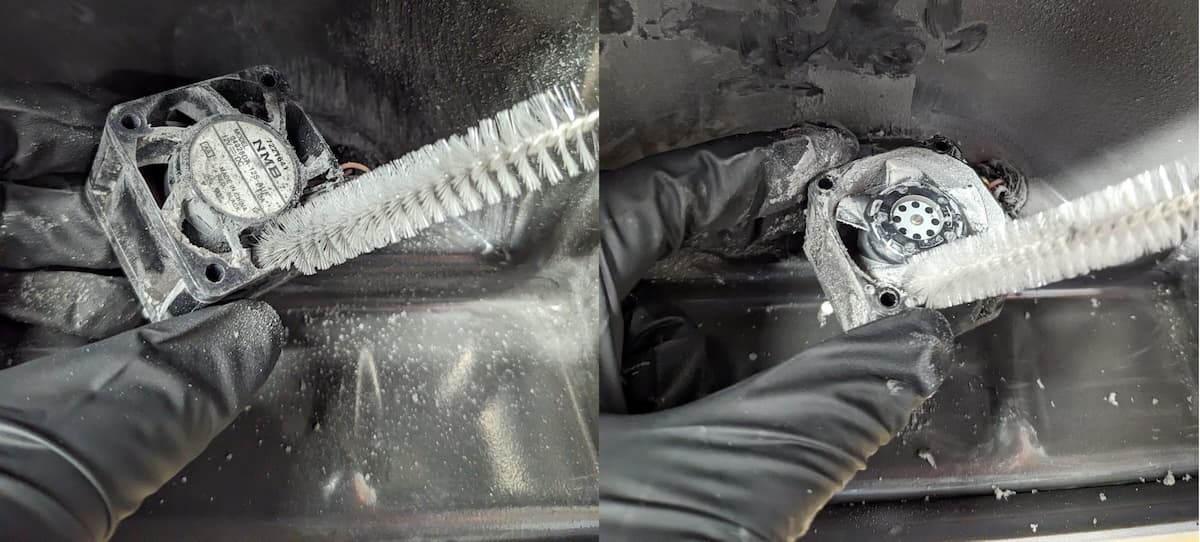
  1. Clean both sides of the fan with a small pipe cleaning brush, inserting it between the impeller blades.
  2. Set the exhaust fan aside.
Cleaning the fan blades on a Fuse 1 exhaust fan
Fuse 1 only: Clean the exhaust tubeFuse 1+ 30W only: Clean under the exhaust fan
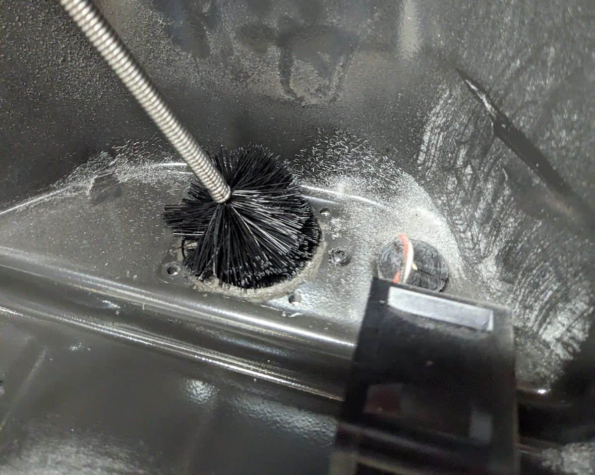
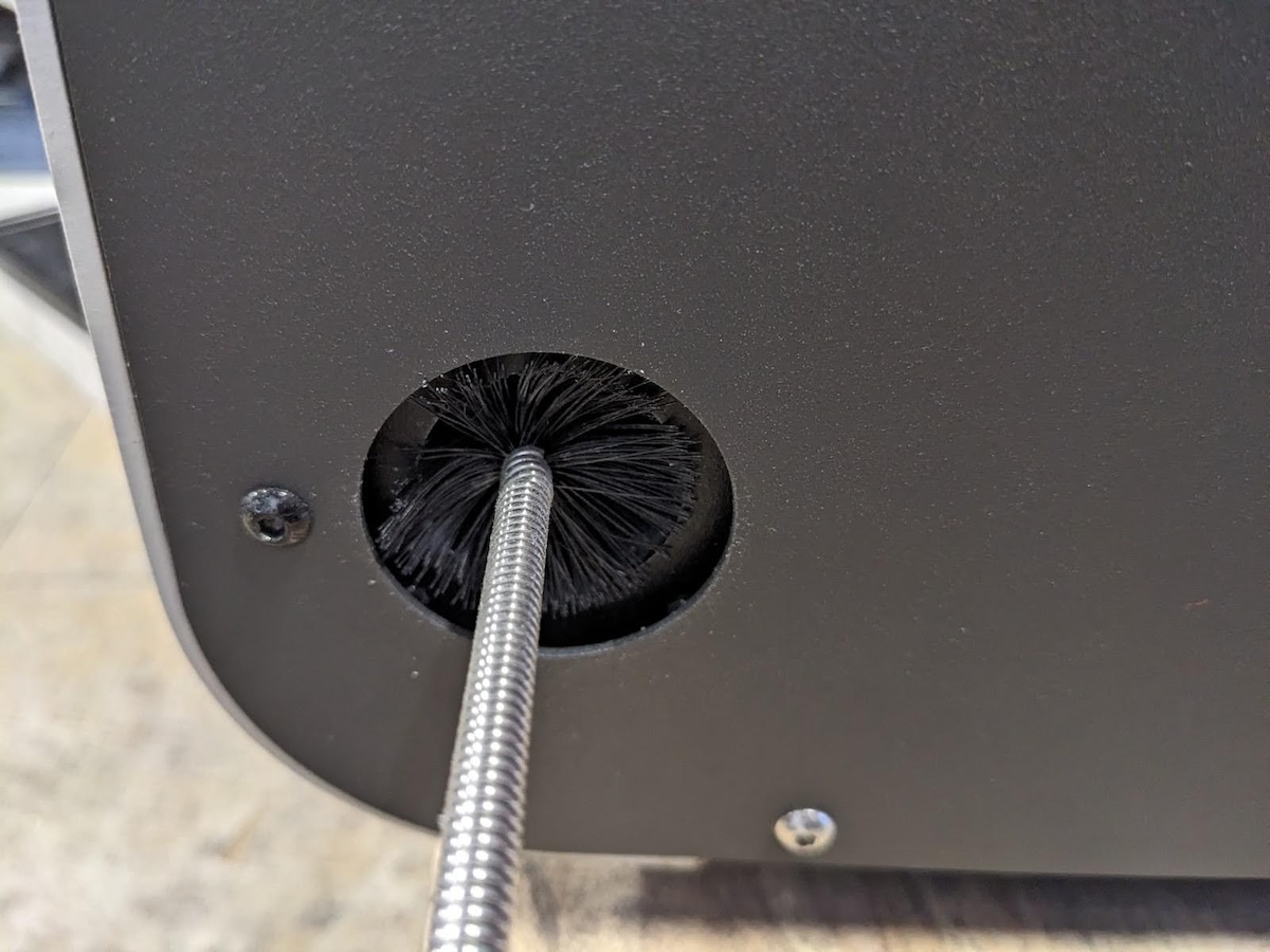
  1. Insert a large pipe cleaning brush into the opening underneath the fan and into the exhaust port on the rear of the machine to clear any blockages. Use a vacuum to clean the dislodged debris.
Cleaning the exhaust tube on a Fuse 1 Cleaning the exhaust tube on a Fuse 1
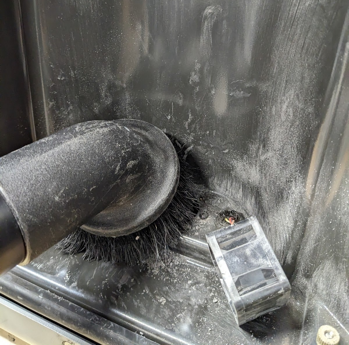
  1. With the exhaust fan removed and cleaned, vacuum any debris from the filter cabinet and through the hole where the fan was attached.
Vacuuming under the exhaust fan on a Fuse 1+ 30W
  1. Use the 2.5 mm hex screwdriver to reinstall the four screws that fasten the fan to the cabinet. Make sure that the fan is installed in the correct orientation, with the sticker facing down. Installing the fan upside-down can result in error messages or print failures.
  2. Reinstall the exhaust filter with the black gasket facing away from you, then re-engage the retainer.
  3. Close the filter cabinet door.

Cleaning the intake filter

The intake filter is located behind a cabinet door on the right side of the printer. Vacuum the filter if the printer is showing low pressure warnings.

To clean the intake filter:

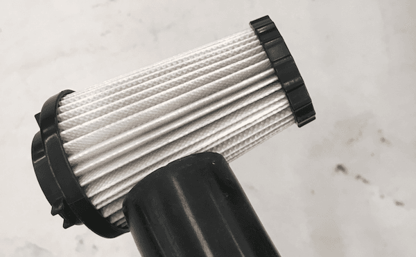
  1. Open the filter cabinet door on the right side of the printer. The intake filter is the conical filter on the left side.
  2. Grip the base of the conical filter and gently twist it in a counterclockwise direction to disengage the snap-fit tabs. Remove the intake filter aside.
  3. Vacuum the recess behind the intake filter bay.
  4. Clean the intake filter. Slowly move the hose inside the pleats of the filter to ensure all powder is removed.
A vacuum hose is being brought to the intake filter
  1. Vacuum the area behind and around the intake filter to clean any stray powder and laurolactam buildup.
  2. Reinstall the intake filter by aligning the tabs on the collar with the corresponding grooves on the mount inside the cabinet and turning in a clockwise direction.
The intake filter has been removed from the cabinet and a vacuum hose is being brought to the resulting cavity

Repairing the exhaust tube

It is possible to tear the exhaust tube during cleaning. You may feel the tube tear or notice pressure-related errors during subsequent prints. To repair a torn exhaust tube:

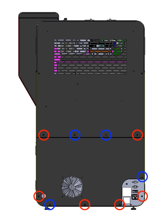
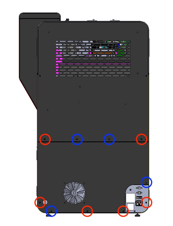
Removing the screws securing the lower rear panel to a Fuse 1 generation printer

Notice:

The placement of the chrome screws is critical to the printer's electrical grounding. Refer to the image on the right for the correct locations of the black screws (circled in red) and chrome screws (circled in blue).

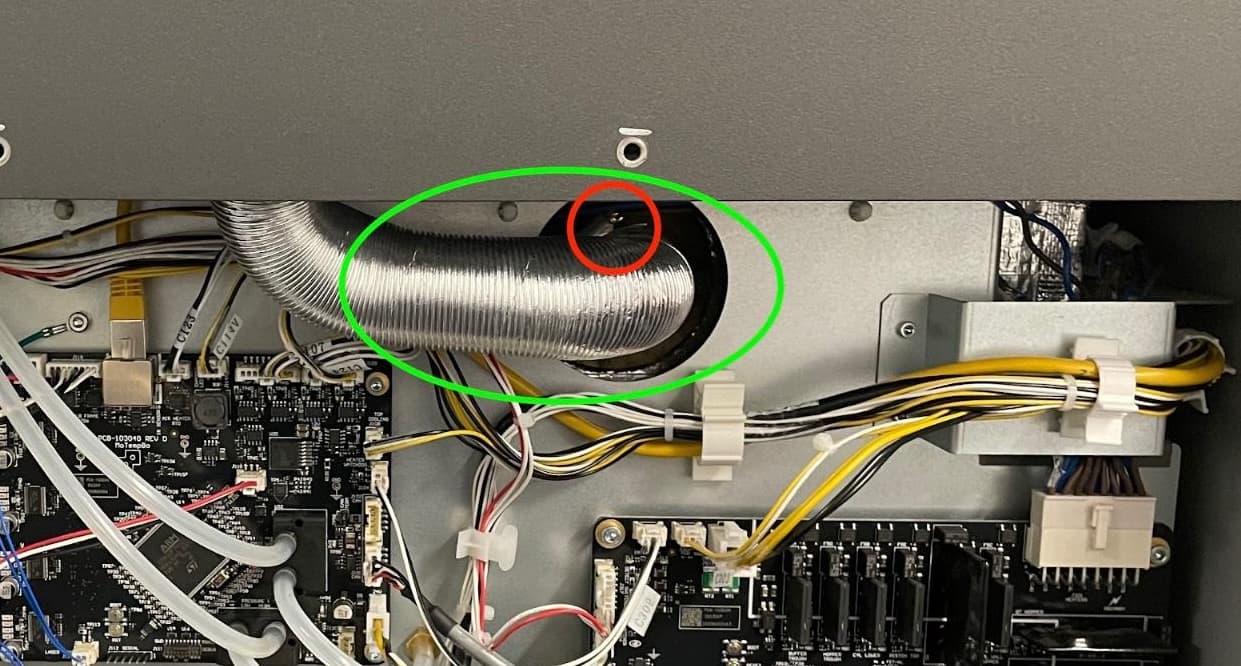
  1. Identify the aluminum exhaust tube and locate the damaged section. Patch any tears with aluminum tape. If necessary, you can remove the exhaust tube from the printer for better access:
    1. Locate the screw for the ring clamp securing the tube to the printer.
    2. Using a 6.5mm slotted screwdriver, loosen but do not remove the ring clamp screw so that the tube can be pulled away from the exhaust pipe.
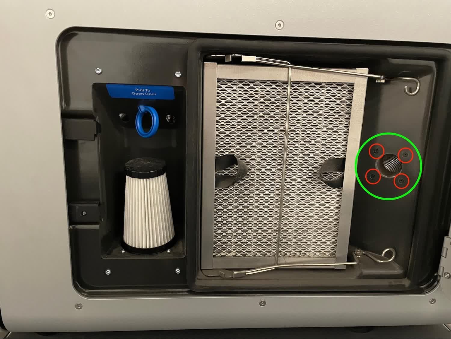
    3. Open the filter cabinet door and locate the exhaust inlet on the right-hand side of the cabinet.
    4. Use a 2 mm hex driver to remove the 4x 8 mm M3 countersunk screws flanking the inlet.
    5. Remove the exhaust tube from the printer and patch any tears using aluminum tape.
Fuse 1 generation exhaust tube location
  1. If you removed the exhaust tube from the printer to repair it, reinstall it:
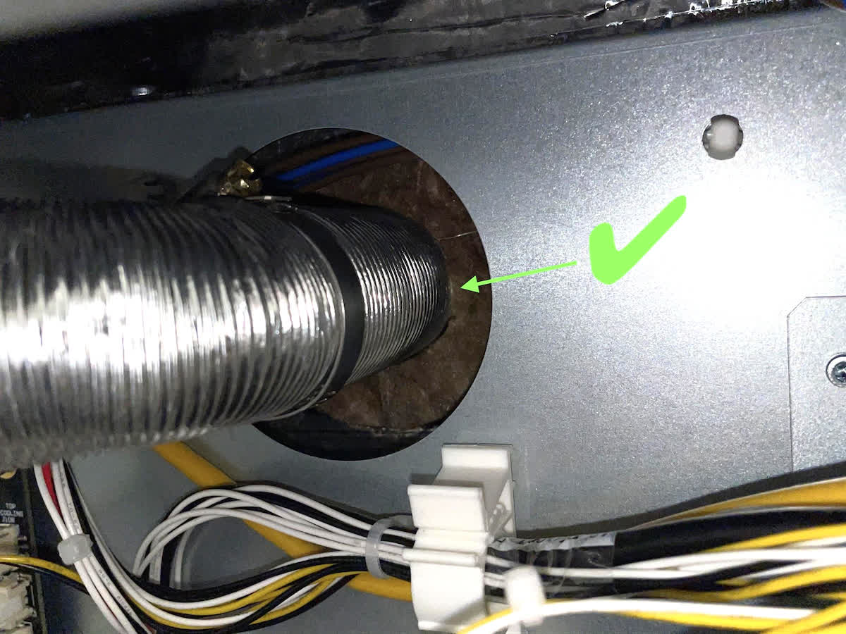
    1. Slide the ring-clamped end of the tube back onto the exhaust pipe. Ensure that the tube is pressing up against the insulation panel.
    2. Use a 6.5 mm slotted screwdriver to tighten the ring clamp screw.
    3. Use a 2 mm hex driver to secure the other end of the exhaust tube to the back of the filter cabinet. Be sure to firmly re-thread the 4x 8 mm M3 countersunk screws so there is no gap between the mounting plate and the filter cabinet housing.
alttext

Notice:

Check the seal of the exhaust duct by shining a flashlight around the inlet inside the filter cabinet. If light is visible behind the filter cabinet, the duct is not properly sealed.

  1. Use a 2.5 mm hex driver to replace the six black and four chrome 6 mm M4 button screws that secure the lower-half of the rear panel to the printer.
Reinstalling the screws securing the lower rear panel to a Fuse 1 generation printer

Notice:

The placement of the chrome screws is critical to the printer's electrical grounding. Refer to the image on the right for the correct locations of the black screws (circled in red) and chrome screws (circled in blue).

  1. Replace the Wi-Fi antenna, if previously installed.
  2. Fuse 1+ 30W only: Reconnect the nitrogen source to the quick-disconnect fitting, if previously installed.
  3. Reconnect the printer to its power source, then turn the printer on.