複合材料、特に炭素繊維(カーボンファイバー)強化プラスチックは、その高い汎用性と効率性から、航空宇宙から医療まで様々な市場でイノベーションを促進しています。この材料はスチール、アルミニウム、木材、樹脂などの従来の材料を上回る性能を持ち、高性能で軽量な製品の製造を可能にします。
このガイドでは、カーボンファイバー部品の製造の基本、様々なカーボンファイバーのレイアップ、ラミネート、成形方法、そして3Dプリントの活用でコストと時間を削減しながらカーボンファイバーの成形型を作成する方法について解説します。直接3Dプリント可能な複合材料もあります。たとえばFormlabsのNylon 11 CFパウダーは、優れた剛性と強度を両立させたい用途に最適なカーボンファイバー強化材料です。FormlabsのFuse 1+ 30WとNylon 11 CFパウダーの組み合わせにより、構造的・熱的に安定し、繰り返しの衝撃にも耐えられる硬質な軽量部品を製作できます。
Nylon 11 CFパウダーの無償サンプルパーツをリクエスト
カーボンファイバー強化ナイロン材料の品質を、ぜひお手にとってお確かめください。サンプルパーツを無償でお届けいたします。
複合材料の基礎知識
複合材料とは、2つ以上の成分を組み合わせ、それぞれの単独成分とは異なる特性を持つ材料のことです。通常、強度、効率性、耐久性などのエンジニアリング特性が向上します。複合材料は、強化材(繊維や粒子)と、それらを結合するマトリックス(ポリマー、金属、セラミック)で構成されます。
現在、繊維強化プラスチック(FRP)が市場を支配し、様々な業界で新たな活用法が次々と出てきています。その中でも、炭素繊維はアルミニウムの3倍以上の強度と剛性を持ちながら40%軽量であるため、航空機、レーシングカー、自転車などで広く使用されています。強化炭素繊維をエポキシ樹脂で結合することで構成されます。
繊維を一方向に配置して特定の方向の強度を高めたり、クロス織りして複数方向の強度を持たせたりすることが可能なほか、クロス織りで複合部品の特徴的なキルティング模様を生み出すこともできます。両方を組み合わせて部品を製造することも一般的です。利用可能な繊維の種類は以下の通りです。
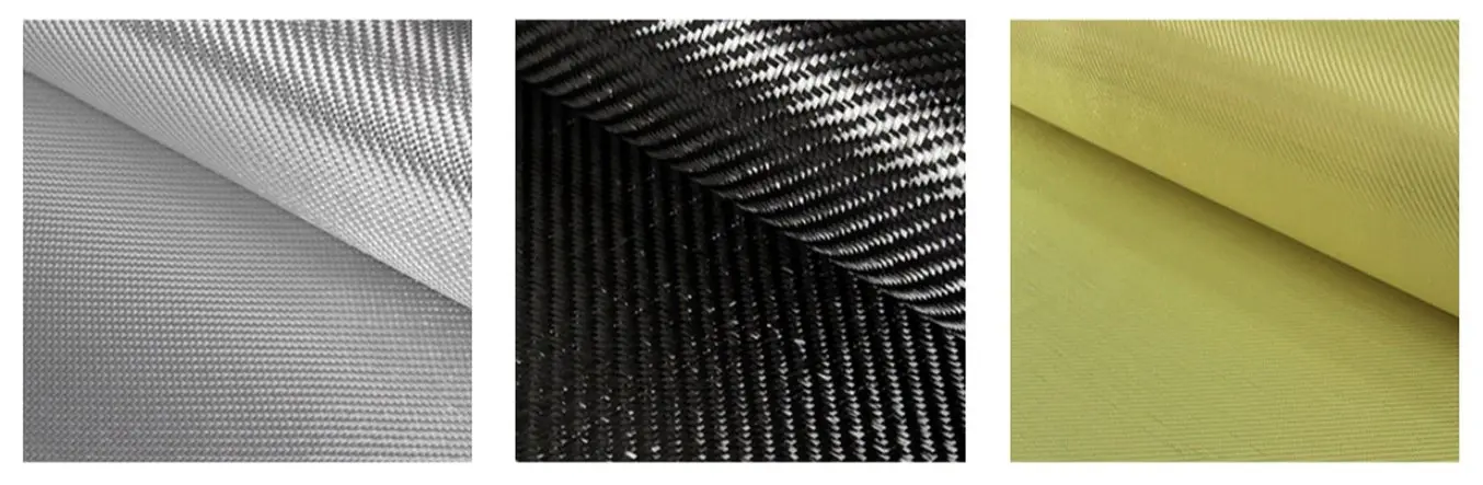
| ガラス繊維 | 炭素繊維 | アラミド繊維(ケブラー) |
|---|---|---|
| 最も一般的な繊維 軽量で、適度な引張・圧縮強度 低コストで加工が容易 | 業界最高の強度・剛性(比強度、比剛性) 他の繊維より高価 | 炭素繊維より高い耐衝撃性・耐摩耗性 低い圧縮強度 切断や加工が難しい |
繊維を結合して硬質の複合材料を作るためには、樹脂が使用されます。数百種類の樹脂が使用可能ですが、最も一般的なものは以下の通りです。
| レジン | 長所 | 短所 | 二次硬化 |
|---|---|---|---|
| エポキシ | 最高の最終強度 最軽量 最長の保存期間 | 最も高価 混合比や温度変化に敏感 | 特定の硬化剤が必要(二成分系) エポキシの種類により加熱が必要な場合あり |
| ポリエステル | 使いやすい(最も一般的) 紫外線への耐性あり 最も低コスト | 強度と耐腐食性が低い | 触媒(MEKP)で硬化 |
| ビニールエステル | エポキシの性能とポリエステルのコストを併せ持つ 最高の耐腐食性、耐熱性、伸び率 | エポキシより強度が低く、ポリエステルよりコストが高い 保存期間が短い | 触媒(MEKP)で硬化 |
無料相談セッションのご予約
3D プリントのエキスパートに一対一でご相談いただける相談セッションをご用意しています。ROI 分析やテスト・プリントなどを通して、お客様のビジネスに最適なソリューションを一緒に考えましょう。
炭素繊維部品を製造する3つの方法
炭素繊維部品など、繊維強化プラスチックの製造はスキルと労力を要するプロセスで、一品ものからバッチ生産まで幅広く行われています。サイクルタイムは部品のサイズと複雑さに応じて1時間〜150時間です。通常、連続した繊維をマトリックスで結合して個々のプライを形成し、それらを層ごとに積層して最終的な部品を製作します。
複合材の特性はラミネート過程のみでなく使用する材料によっても変わり、繊維を取り込む方法が部品の性能に大きく影響します。熱硬化性樹脂は、補強材とともに成形型や金型で形作られ、硬化して頑丈な製品となります。様々な積層技術がありますが、主に以下の3つに分類できます。
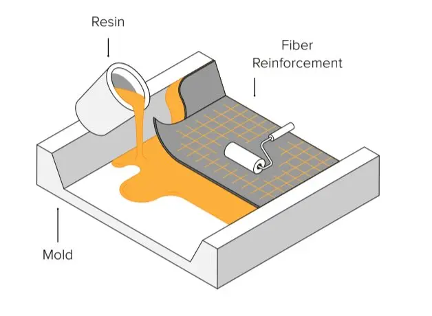
1. ウェットレイアップ
ウェットレイアップでは、繊維をカットして金型に敷き、その上からブラシ、ローラー、スプレーガンで樹脂を密着させます。この方法は高品質な部品を作るためには最も技術力が必要になりますが、DIYで炭素繊維部品を作るのに最もコストが低く、始めやすい方法です。炭素繊維部品の製造に初めて取り組む場合や設備が整っていない場合は、手作業によるウェットレイアップから始めることをお勧めします。
上の動画では、炭素繊維のウェットレイアップ成形の工程を紹介。
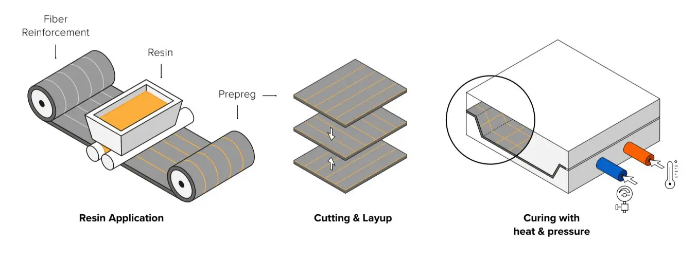
2.プリプレグ積層
プリプレグ積層では、樹脂があらかじめ繊維に含浸された状態でプリプレグシートとして硬化を防ぐために冷蔵保存されています。その後、オートクレーブ内で熱と圧力をかけてプライを金型内で硬化させます。樹脂の量が制御されているためより正確で再現性の高いプロセスですが、最も高価な技術であり、高性能な用途で使用されます。
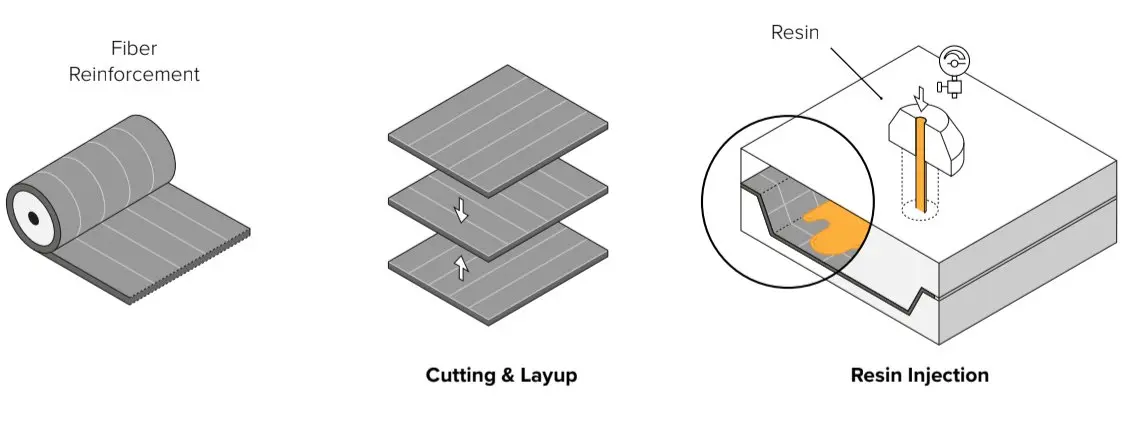
3. レジントランスファーモールディング(RTM)
RTMでは、乾燥した繊維を二つ割の金型の中に入れ、その後金型をクランプで閉じ、高圧をかけて樹脂をキャビティ内に押し当てます。工程が自動化されていることが一般的で、大量生産に使用されます。
3Dプリント製の型で炭素繊維部品を製造する
成形型の品質は最終的な製品の品質に直接影響するため、FRP製品の製造において成形型の製作プロセスが非常に重要なポイントになります。成形型の多くはワックス、フォーム、木材、プラスチック、金属を使用してCNC加工または手作業で製作されています。手作業で製作する場合は非常に労力がかかりますが、CNC加工も複雑で時間のかかる工程を必要とし、特に複雑な形状の場合はその傾向が強くなります。一方、外部委託は高コストで製作期間も長くなりがちです。どちらの方法も熟練の技術者を必要とし、デザインの試作・検証や成形型の細かな調整を柔軟に行うことができません。
アディティブマニュファクチャリングは、カーボンファイバー部品用の成形型や原型を迅速かつ低コストで製作するソリューションとなります。製造プロセスにおけるポリマー型の使用は増加し続けています。金型を内製のプラスチック型に置き換えることで成形型の製作期間を短縮し、設計の柔軟性も高まる強力でコスト効率の高い手段となります。エンジニアは、フィラメントワインディングや繊維の自動配置などをサポートする治具や固定具の製作に、ポリマーレジンを使用した3Dプリント品を活用しています。同様に、短時間でプリントした成形型やダイを使って、射出成形、熱成形、シートメタル成形などによる少量バッチの生産が行われています。
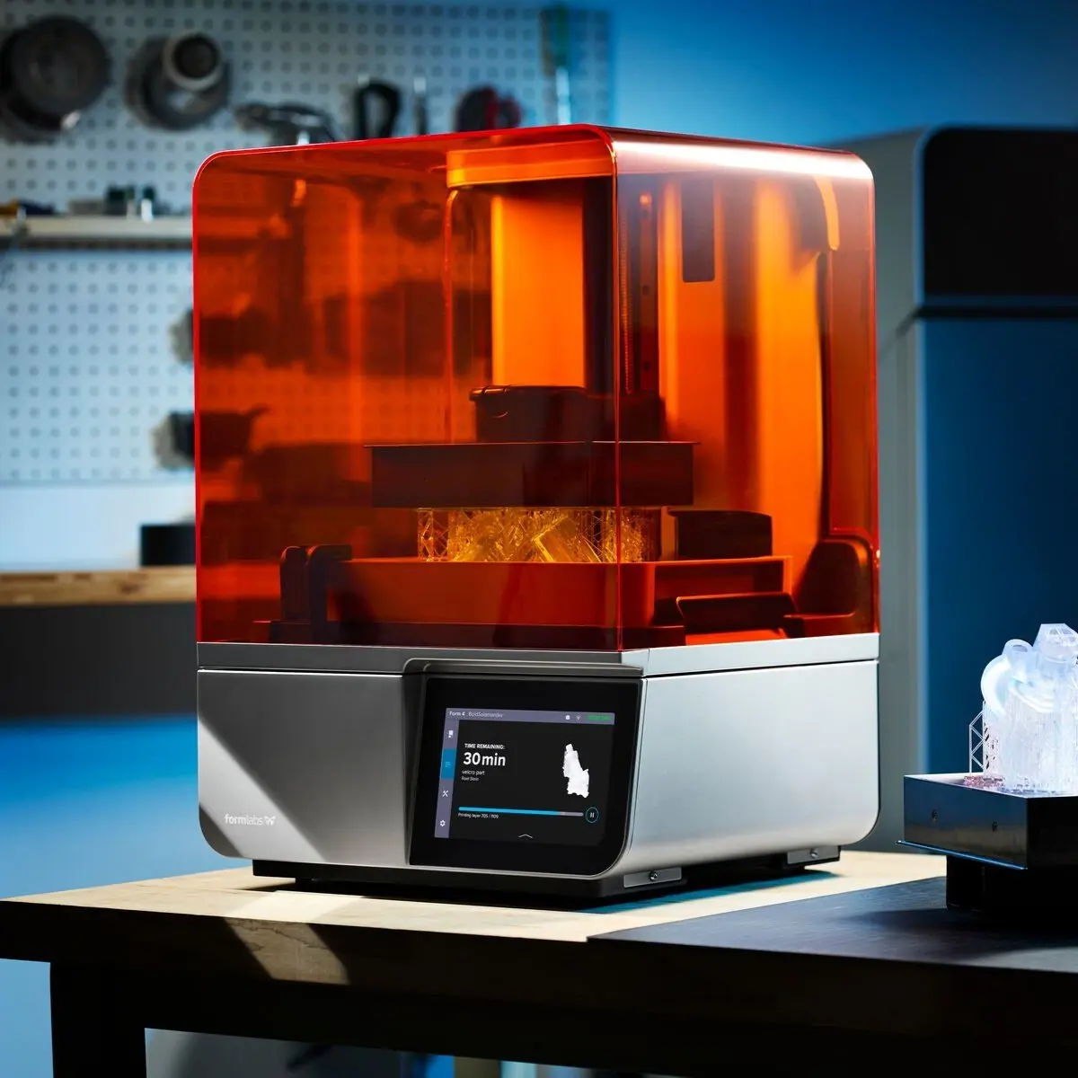
社内導入可能なデスクトップサイズの3Dプリントは必要な設備が少なく、ワークフローの複雑さが軽減されます。Form 4のような工業品質のデスクトップサイズ光造形3Dプリンタは価格も手頃で導入が容易、かつ需要に応じて生産規模を迅速にスケールアップできます。Form 4Lのような大容量の3Dプリンタを使用すれば、大型の成形型や治具の製作も可能です。
SLA光造形方式3Dプリントは、カーボンファイバーのレイアップ成形型に不可欠な、非常に滑らかな表面仕上げや高精度で複雑な形状も実現できます。さらに、Formlabsのレジンライブラリには成形型や原型の製作に適した機械的・熱的特性を備えたエンジニアリング系材料が豊富に揃っています。
3Dプリント製の成形型を使用してカーボンファイバー部品を製造することで、コストを削減し、製作期間も短縮できる。
小規模生産の場合は、エンジニアは成形型を低コストで数時間以内に直接3Dプリントできます。手作業で材料を掘り出したり、CNC加工機やCAMソフトウェアの取り扱い、機械のセットアップ、ワークの固定、切削、切りくずの除去などが必要ありません。成形型の製作にかかる作業量と製作期間が大幅に削減されることで、デザインの試作・検証を迅速に繰り返したり、部品のカスタマイズが可能になります。また、従来の方法では製造が困難だった繊細なディテールを持つ複雑な成形型も製作できます。
型の構造とデザインガイドライン
金型設計にあたっては、どのような材料で造形すれば成功するか、そしてその金型がどのような製品の製造に役立てられるかという点を、まず検討します。様々な形状の部品を作るために、様々な構造の金型が使用されます。
- 真空バッグ成形(一つ割型):片面に高い光沢度(Aクラス仕上げ)を必要とする部品の製造に最適です。どちら側がAクラス側になるかで凹凸が変わりますが、片面は成形型面、もう一方は真空バッグ面になります。
- 圧縮成形(二つ割型):両面ともAクラスの仕上がりとする必要がある場合に使用されます。両面とも成形型面になります。
- 圧力成形(ブラダー型):真空バッグ型や圧縮成形型では対応できない、離型が困難な複雑形状の部品の成形に最適です。片面は成形型面、もう一方はブラダー面です。
- ネガ型作成用の原型:量産体制の確立や生産性の向上を目指し、複数の成形型が必要となる場合に活用できます。一つの型で複数の成形に対応します。

抜き勾配をつける:2~3度の抜き勾配をつけることで離型がスムーズになり、特に硬い型では型の寿命を延ばすことができます。しかし、Tough 1500レジンのような柔軟な3Dプリント材料を使うことで、硬質材料では実現が難しい複雑な形状でも抜き勾配なしで製作が可能になります。材料の厚みに応じた最小半径を設定する:コーナーでのファイバーの整列が促進され、エアの混入を防ぎます。これにより、再現性の高い、高品質な部品を確実に作成できます。急な、あるいは近接したコーナーを避けられるため、箱型でエッジの効いたデザインよりも、流れるようなジオメトリーの方が扱いやすくなります。
材料の厚みに応じた最小半径を設定する:コーナーでのファイバーの整列が促進され、エアの混入を防ぎます。これにより、再現性の高い、高品質な部品を確実に作成できます。急な、あるいは近接したコーナーを避けられるため、箱型でエッジの効いたデザインよりも、流れるようなジオメトリーの方が扱いやすくなります。

位置決めピンとインデント:成形型の正確な位置合わせを行います。3Dプリントの大きなメリットの一つは、複雑なアライメント形状でも実現を可能にし、高い位置精度が求められるデザインの製作をサポートできることです。
表面のオーバーラン:余分な表面の余分な材料は、トリムラインに合わせて正確に切り落とします。3Dプリントでは、バリ取りなどを必要とせずにオーバーランを含めての造形が可能です。
トリムラインの追加:3Dプリントでは、ドリルガイド、手作業によるトリミング用のケガキ線(スクライブライン)、ルーターガイドレールといった、精密な仕上げを可能にする要素を設計に組み込むことができます。
その他のベストプラクティス:
- 解像度と離型のしやすさを最適化するため、可能な限り薄い積層ピッチでプリントする
- 表面をよりきれいに仕上げるため成形面にはサポート材を使用しない
- 離型剤を使用する(離型工程では必須)
- 気泡の混入を防ぐため、レジンを混ぜ合わせた後、気泡が抜けるまで2分ほど静置する。レジンの最初の層をハケでブラッシングし、もう一度繰り返す。(小さな気泡が残った場合でも、後処理で研磨して塞ぐことができます)
ケーススタディ:ベルリン工科大学がカーボンファイバー型を3Dプリント
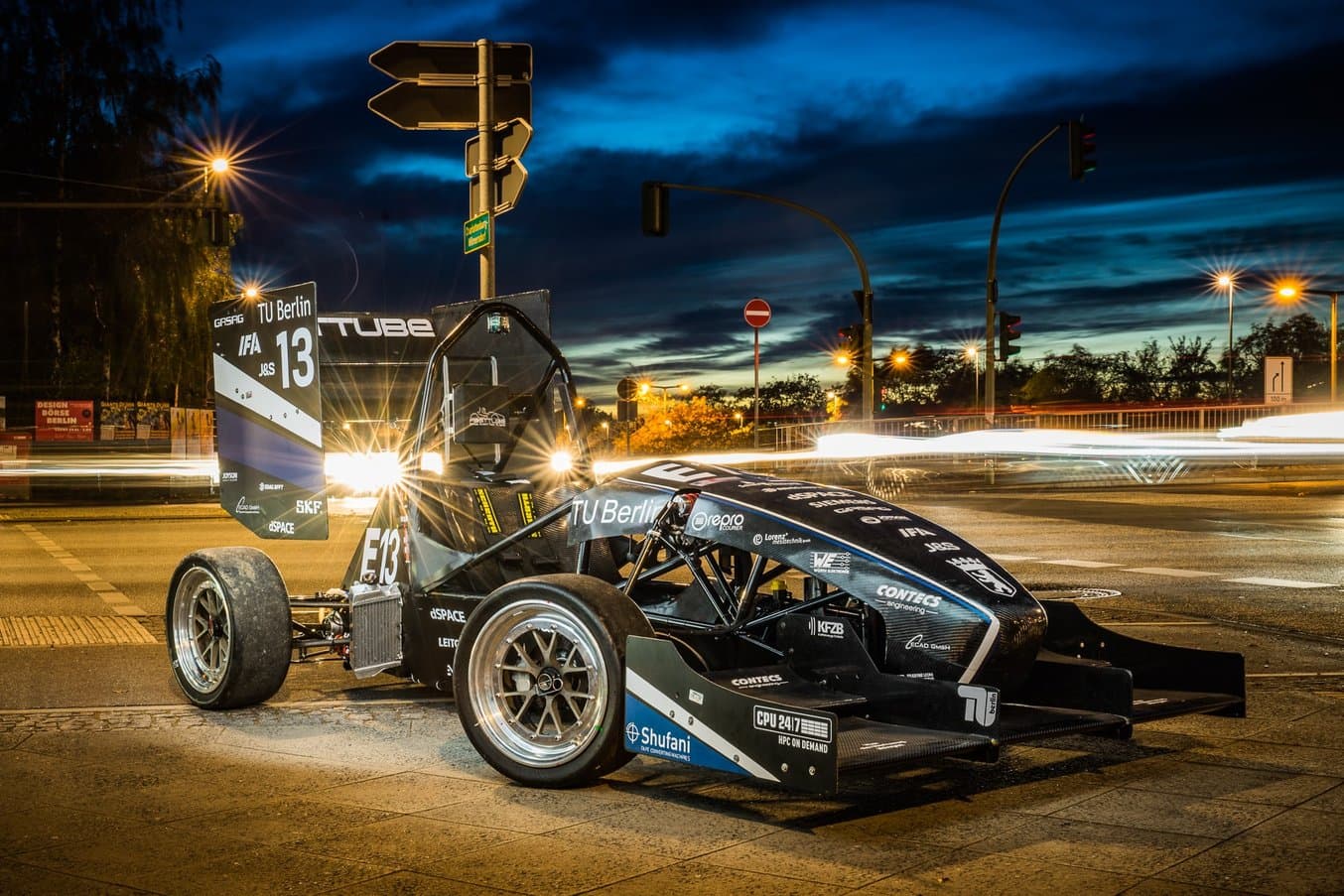
学生フォーミュラは、年に一度開催されるエンジニアリングデザインのコンテストで、世界中の学生チームがフォーミュラスタイルの車両を自ら設計・製造し、競い合う大会。ベルリン工科大学の学生フォーミュラチーム(FaSTTUBe)は最大規模グループの1つで、2005年以来、80~90名の学生が新たなレーシングカーの開発を行っている。
ベルリン工科大学の学生フォーミュラチーム(FaSTTUBe)は最大規模グループの1つで、2005年以来、80~90名の学生が新たなレーシングカーの開発を行っています。
ほぼ全ての3Dプリント技術にアクセスできるFasSTTUBeチームは、次の3つの目的で3Dプリントを活用しています。
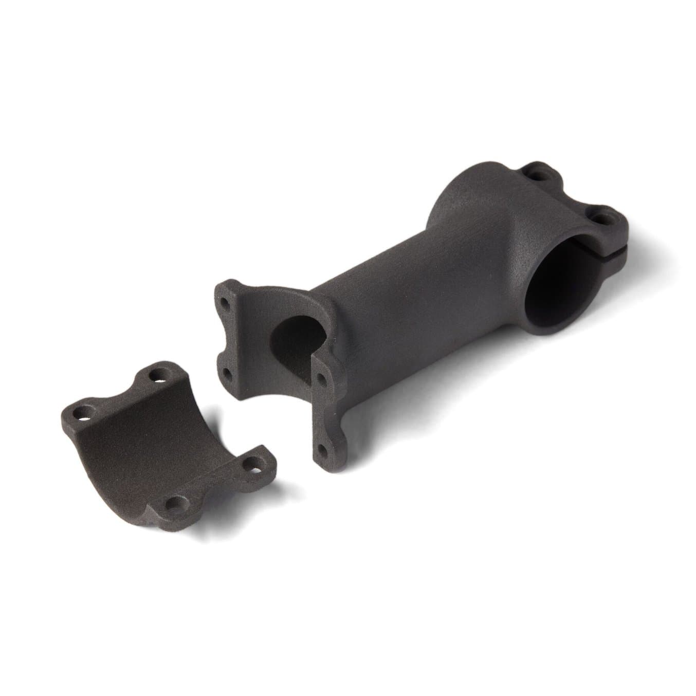
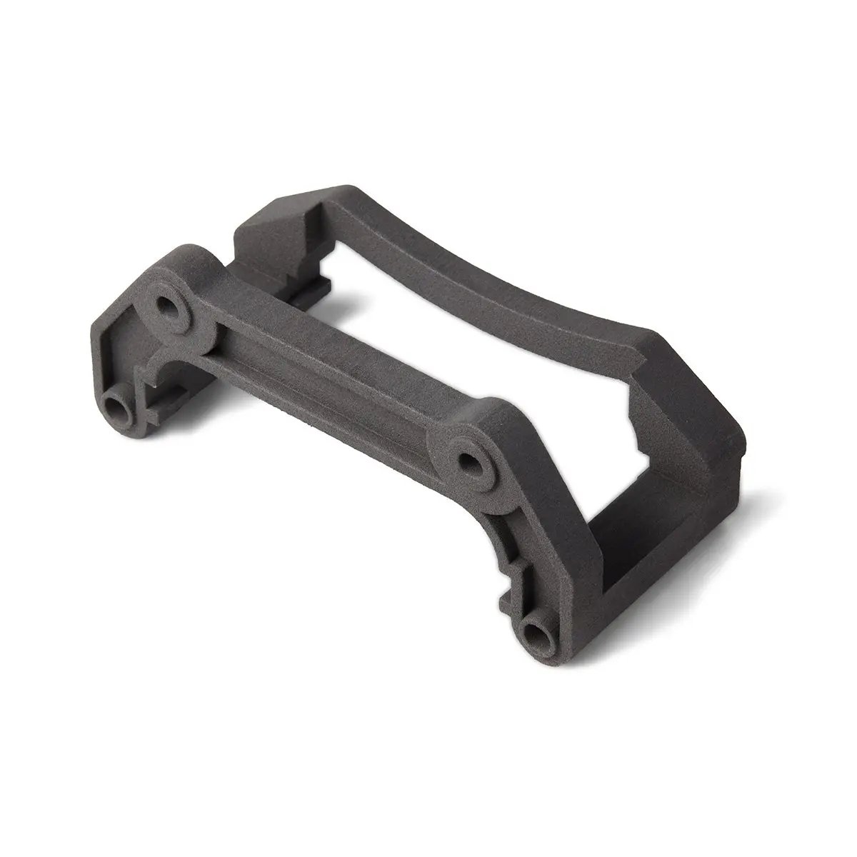
- 試作品:アンチロールバーの取付部やHVバッテリーテスターなど、様々なパーツの試作品を3Dプリントで製作
- 3Dプリント製のカーボンファイバー成形型:他の方法では実現不可能なカーボンファイバー部品の製作のために12個の成形型をプリント
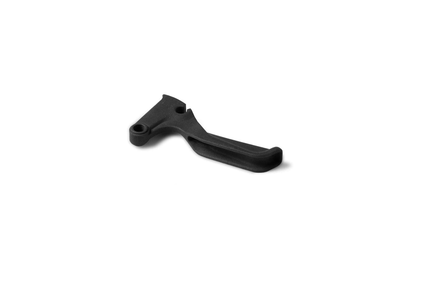
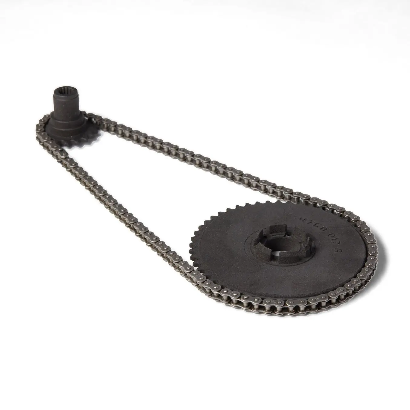
- 実製品用部品:最終車両に搭載されるボタンホルダーやステアリングホイールのシフトレバー、冷却システムのホース、センサーコネクターなど、約30種類の部品を3Dプリンタで直接製造
本ケーススタディでは、カーボンファイバーを使ったステアリングホイールのハウジングとグリップの製作に採用された、3Dプリントの成形型製作の詳細に迫ります。
レーシングカーにとって、軽量化は絶対条件です。軽量化のために、中空構造のステアリンググリップを造形することも可能でしたが、それではドライバーの握力に耐える強度を確保できず、採用が見送られました。カーボンファイバーは、強度を維持または向上させながら大幅な軽量化を可能にする優れた材料です。今年、カーボンファイバー部品の製造を可能にするため、エアロダイナミクスおよびカーボン生産部門の責任者Felix Hilken氏はウェットレイアップ用の成形型を3Dプリントするワークフローを開発しました。
必要なもの:
- Formlabs Tough 1500レジン対応のSLA光造形プリンタ
- カーボンファイバー:200g・3K・0.3mmの3層構造、綾織り
- 離型剤:ワックス、ポリビニルアルコール
- 高強度エポキシ樹脂
- ブラシとハサミ
- 真空バッグ、真空ポンプ、ブリーザークロス
- サンドペーパー

1. 成形型を設計する
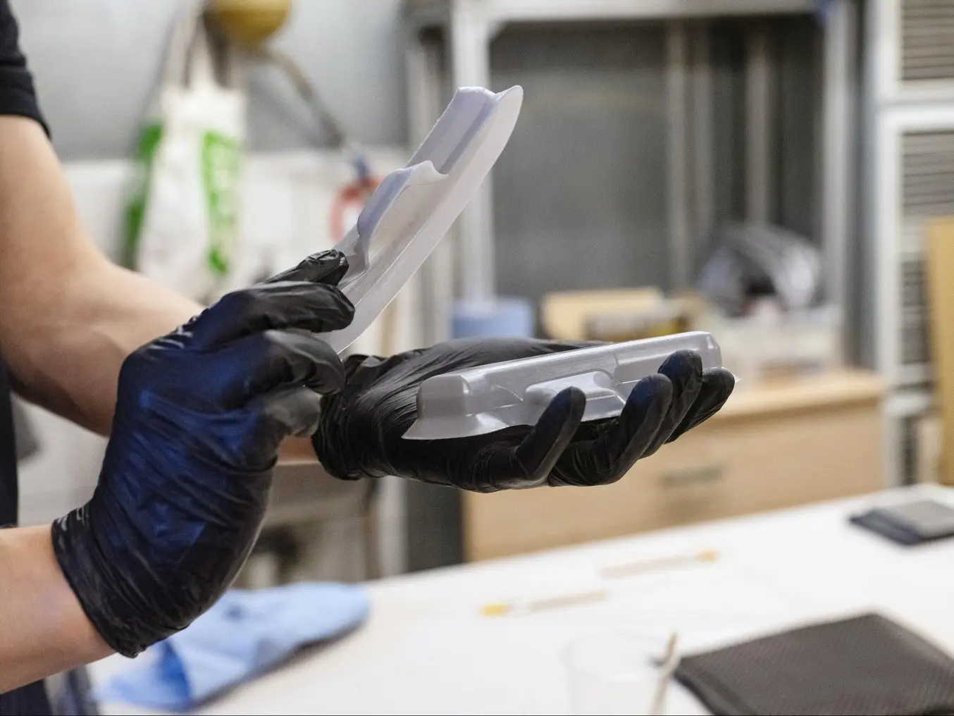
グリップは離型性を考慮し、2パーツに分割して製造されました。グリップの各パーツを成形するにあたり、Felix氏は特に3Dプリントを用いなければ製造が難しいフィーチャーを取り入れた二つ割の型を設計しました。
- タイトな内R、スイープ曲面、曲率の異なるサーフェスなどの細かなフィーチャー
- アルミ型から理型できなかった丸いタイトエッジ
- 位置決めに敏感な部品のため、穴あけ位置にインデントを設置

2. 成形型の3Dプリント
FormシリーズプリンタでTough 1500レジンを使い、積層ピッチ50ミクロンでプリントしました。造形品はIPAで10分間二次洗浄した後、70℃で60分間、後硬化を実施します。伸び率と弾性率のバランスに優れていることから、Tough 1500レジンが選ばれました。この材料でプリントした部品は、大きく曲げてもすぐに元の形状に戻ります。これは、離型時の型割れを防ぐために求められる機械的特性です。

3.1 ハンドラミネート:離型剤を塗布する
離型を容易にするために、成形型に離型剤を塗布します。成形型の内面に離型剤で覆われていない箇所があると、成形品を取り出しにくくなります。
- ワックスを塗布する(任意だが推奨)
- ポリビニルアルコール(PVA)を塗布する

3.2 レジンと硬化剤を混ぜ合わせる
レジンと硬化剤を混ぜ合わせます。この際、混合比は正確に厳守してください。目標比率から数パーセントでもずれると、部品が柔らかくなりすぎたり、十分に硬化(重合)しないことがあります。レジンメーカーの指示と安全上の注意事項を必ずご確認のうえ、正しい方法でご使用ください。Felix氏の場合、レジンを混合から2時間後に重合プロセスが始まるため、レイアップ作業は2時間以内に済ませる必要があります。

3.3 レジンを塗布する
ハケで成形型の凸面にレジンを塗ります。

3.4 カーボンファイバーのレイアップ
カーボンファイバーのプライを成形型の凸面に丁寧に被せます。全ての輪郭にしっかりと沿うようにしてください。織り目の質感と価格の最適なバランスを両立させるため、3Kファイバーを採用しました。複雑な輪郭にもぴったり沿うよう特別にデザインされており、サポート用のストランドは使用していません。

3.5 カーボンファイバーにレジンを塗布する
カーボンプライにレジンを塗布し、レイアップ工程を繰り返します。レジンは各レイヤーを接着し、部品の骨格となるマトリックスを形成するとともに、繊維の再配列を防止します。Felix氏はを3枚のカーボンファイバーを使いました。

3.6 凹型にレジンの最終層を塗布する
凹型にレジンの最終層を塗布したら、気泡が入って繊維内に浸透しないよう、型の両側をしっかりと押し付けます。

3.7 余分な材料を除去する
余分な材料はハサミで切り取ります。

3.8 硬化
真空バッグで48時間硬化させます。この重合プロセスでは、真空バッグで脱気し、プライを常温で成形型に密着させることで、余分なレジンを除去します。レジンとファイバーの体積比が最適化されることで部品の剛性を適切に確保します。

4. 後処理・仕上げ
仕上げ:すべての角をやすりで削ります。やすりがけ後のクリーニングのため、Felix氏はPVAを溶かす目的で成形型を30分ほど水に浸し、その後、1500番の細かいサンドペーパーで残ったレジンを丁寧に磨き落としました。
結果
カーボンファイバーを使用することで、チームはステアリングホイールのハウジング重量を120gからわずか21gにまで大幅に軽量化することに成功し、従来の製造方法では極めて困難だった複雑な形状のデザインも実現が可能になりました。「3Dプリントの素晴らしさは、必要な作業量や設備はそれほど変わらずに、形状の複雑さに関わらず簡単に製作できるという点にあります」とFelix氏は言います。
3Dプリントがなければ、高額かつ長い製作期間を要し、特殊な工具が必要となるアルミ型のCNC加工を外注せざるを得なかったでしょう。「成形型をCNC加工する場合には、専用のツールが必要になるだけでなく、機械が空くのを待つ必要もあります。それでいて、こんな単純な形状すら作れなかったのです。特にこの細い角などが良い例です。位置決めをそこまで厳しくしなくて良いよう、ネジを使用しないデザインにする必要がありました」
Felix氏の計算では、Formlabs Tough 1500レジンによる造形品一つで、約10個分の部品をまかなうことができます。手作業による工程のため、実際の成果はオペレーターのきめ細やかな注意力に左右されますが、3Dプリント製の型を複数利用すれば生産量を高めることができます。成形型の耐用期間を延ばすもう一つの手段として、金属製の汎用金型を併用する方法があります。3Dプリント製のヘリサートが形状を形成し、バックアップの金型がそれをしっかりと保持します。簡単な手動切削機があれば、製作が可能です。
| CNC加工による金型制作を外注 | 3Dプリント製の型を内製した場合 | |
|---|---|---|
| 設備 | カーボンファイバー、レジン、ツール、真空バッグ | カーボンファイバー、レジン、ツール、真空バッグ、3Dプリンタ、Tough 1500レジン |
| 金型の製作時間 | 4~6週間 | 2日間 |
| 人件費 | $0 | $300 |
| 材料コスト | $0 | $10 |
| 金型の製作費(合計) | $900 | $310 |
ケーススタディ:Panozの自動車部品をカーボンファイバーで製作
DeltaWing Manufacturingは、アメリカ製の高級スポーツカーを手がけるPanozのために複合部品を製造しています。部品製造にあたり、DeltaWing Manufacturingはプリプレグ積層でカーボンファイバー部品を作る前に、まず原型を切削し、その上に型をレイアップまたは鋳造で成形した後、表面の仕上げを行っていました。
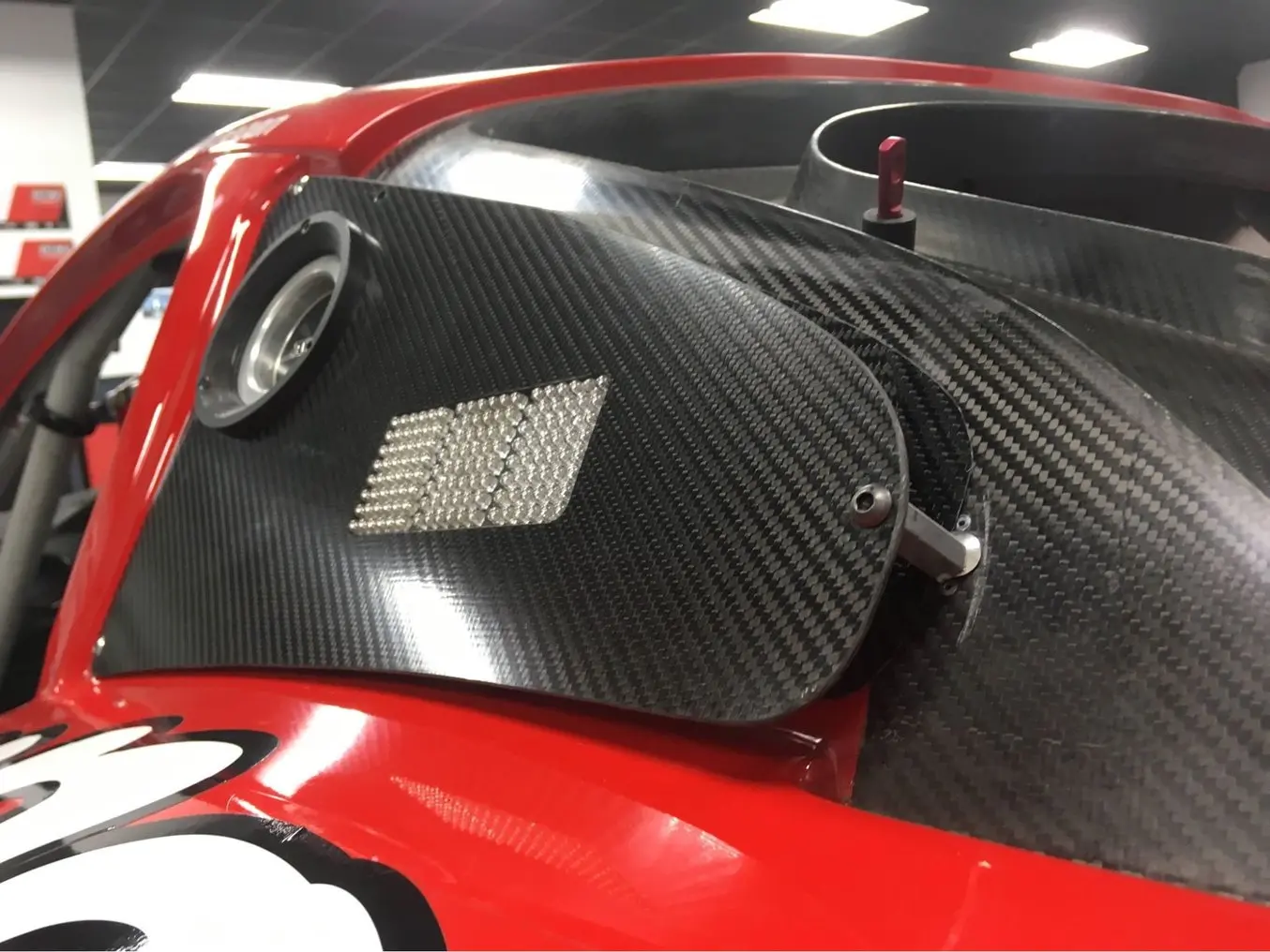
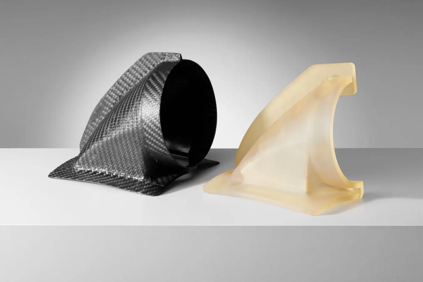
ここ数年で、このプロセスの中間ステップとして、3Dプリント製の内製部品を使用し始めました。Panozは、カスタムレーシングカー向けにカーボンファイバーのエアダクトを6個必要としていました。DeltaWing Manufacturingのエンジニアは、従来の金型製作から作業量と製作にかかる期間を短縮するため、成形型を直接3Dプリントしてプリプレグ工程に組み込むことを選択しました。
必要なもの:
- Formlabs High Tempレジン対応のSLA光造形プリンタ
- カーボンファイバー:4K、二次元模様
- 離型剤:ポリビニルアルコール
- カプトン(ポリイミド)テープ
- 高強度エポキシ樹脂
- ブラシとハサミ
- 真空バッグ、真空ポンプ

1. 成形型を設計する
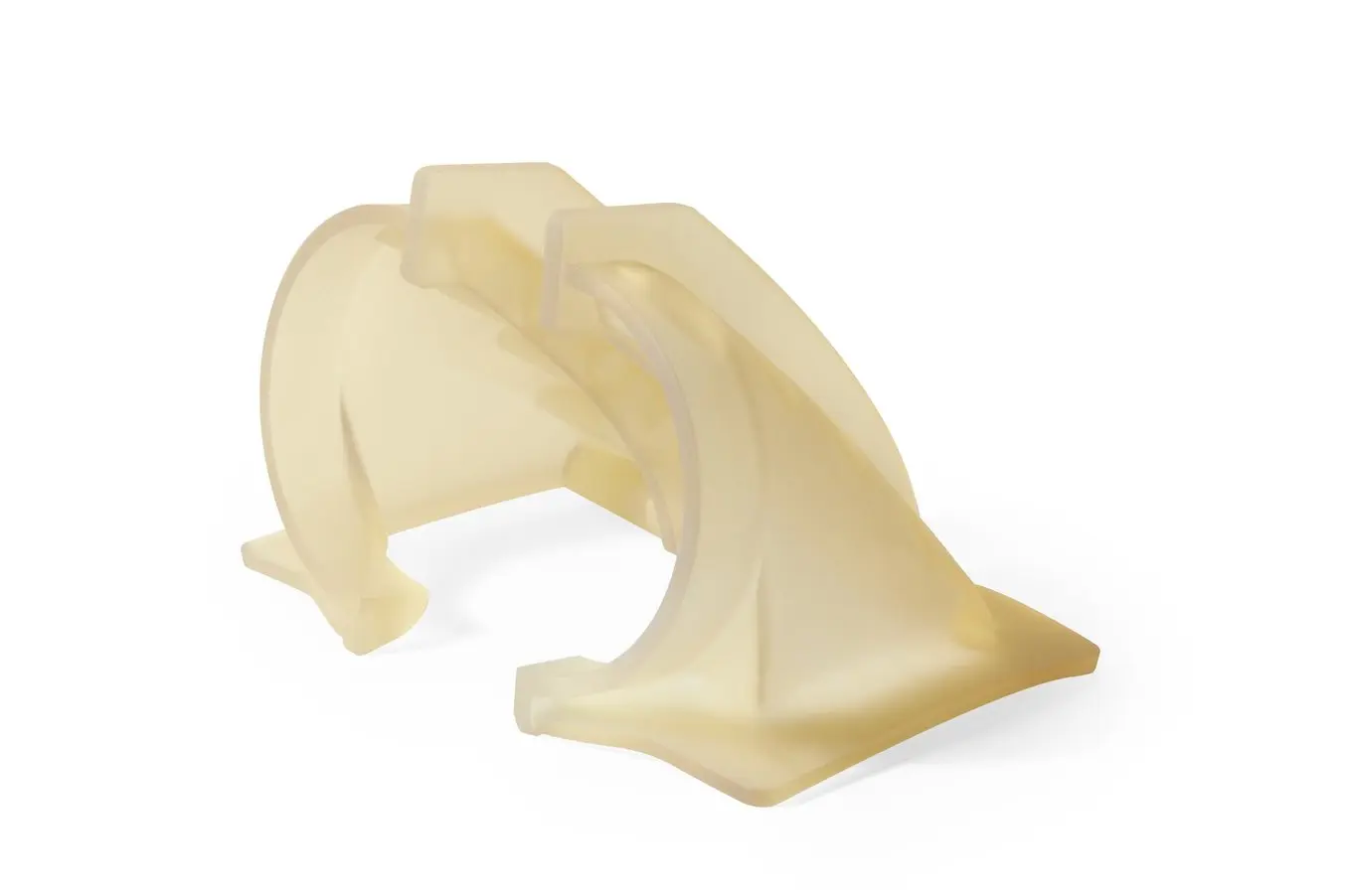
成形品の離型を容易にするため、ダクトは2種類の型を使って別々に成形し、後から接着しました。各型は、Formシリーズプリンタの最大造形サイズに収まるよう2つに分けてプリントし組み立てる方法を取りましたが、より大容量での造形が可能なForm 4Lならその必要はありません。プリントしたモデルは、アディティブマニュファクチャリング用の設計で成形型の推奨設計に従ってデザインされました。

2. 成形型の3Dプリント
DeltaWingは、FormシリーズプリンタでHigh Tempレジンを用い、積層ピッチ100ミクロンで成形型をプリントしました。このレジンが採用された理由は、荷重たわみ温度(HDT)が238℃@0.45MPaと、Formlabsレジンの中でも市場に出ているレジンの中でも最も高い部類に入るためです。
High Tempレジンは高い硬化温度にも耐え、成形時にも形状を維持できる剛性があり、さらに成形品に転写されるディテールを繊細に表現できます。Formlabsは、High Tempレジンでプリントした造形品のHDTを高めるために、IPAで10分間洗浄・80℃で120分間の二次硬化後、160℃で3時間加温することを推奨しています。

3. プリプレグ積層
DeltaWing Manufacturingは、プリプレグ4K二次元模様ファイバーを使用し、3Dプリント製の型で通常のプリプレグ工程を実施しました。成形を繰り返すたびに表面を綺麗にするため、各型の表面をカプトンテープで覆って使用しました。型に繊維を敷き詰めて真空バッグに入れ、オートクレーブで硬化させた後、離型とトリミングを行いました。3Dプリント製の成形型は、38℃で10時間の低速硬化、あるいは126℃で1時間の高速硬化、いずれの条件でも損傷なく耐え切りました。カーボンダクトの両半分は最終工程で接着されます。
仕上げと品質
チームは1つの成形型でテストを6回繰り返しましたが、目立った劣化は確認されませんでした。成形型1つにつき、およそ10回〜15回の反復が可能だと見込んでいます。プリプレグ工程の硬化プロセスではオートクレーブを使って熱と圧力を適用するため、3Dプリント製の成形型が耐えられるのは数回の繰り返しのみになります。そのため、この方法は大量生産には不向きですが、少量生産やマスカスタマイゼーション部品の製造には最適な手段と言えます。高性能スポーツ設備から航空宇宙分野のカスタム治具、さらにはヘルスケア分野における患者専用のカスタム人工装具まで、多岐にわたる応用が可能です。
炭素繊維を使った3Dプリント
従来の炭素繊維部品の強度、耐久性、堅牢性と、3Dプリントの迅速性、形状自由度、再現性を組み合わせたワークフローには、大きな需要があります。そういった背景から、炭素繊維の3Dプリントを提供する多くの3Dプリント企業が存在するのも不思議ではありません。企業は短繊維または連続繊維を使用した炭素繊維3Dプリントを提供しています。
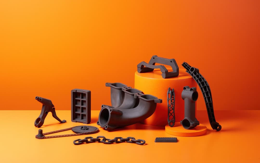
短繊維を使用する場合、SLS(粉末焼結積層造形)方式の工業品質3DプリンタFuse 1+ 30W向けの材料、Nylon 11 CFパウダーを使用すると、メーカーは従来のオーバーレイや加工方法に頼ることなく、強力で軽量、かつ耐熱性のある部品を製作できます。
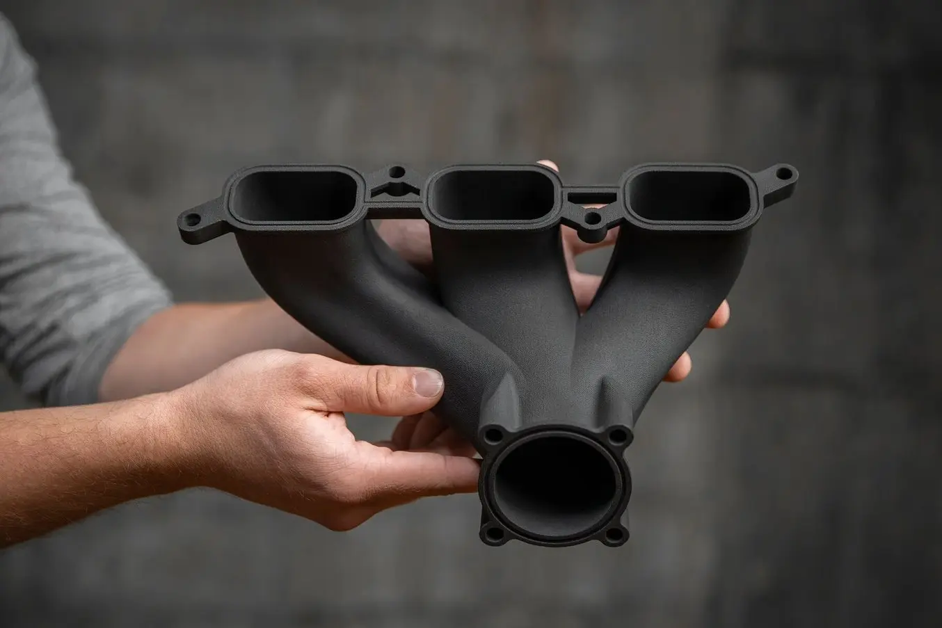
Formlabs Nylon 11 CFパウダーは強度が高く軽量で耐熱性があり、自動車、航空宇宙、製造業での用途に最適な材料。
炭素繊維製造を始める
炭素繊維強化プラスチックを使った製造は、エキサイティングである一方、複雑で多くの作業を必要とするプロセスです。3Dプリント製の成形型や原型を使用してカーボンファイバー部品を製造することで、ワークフローの複雑さを低減し、設計に対する柔軟性や新たな可能性を広げ、コストと製作期間を削減できます。
カーボンファイバーの多くの利点に加え、形状の自由度とよりシンプルで効率的なプロセスのメリットも兼ね備えた3Dプリントパーツの材料として、FormlabsのFuseシリーズSLS 3Dプリンタで使用可能なNylon 11 CFパウダーなどがあります。
お客様用途における3Dプリントを活用したカーボンファイバー部品製造の最適なアプローチについては、Formlabsまでお気軽にお問い合わせください。