Glass fibers and carbon fiber materials are increasingly used in aerospace, marine, automotive, and other high-value industries because they offer high strength and light weight, but they also present a host of manufacturing challenges. The University of Sheffield Advanced Manufacturing Research Centre (AMRC) Composites Centre conducts research using cutting edge methods to solve these challenges.
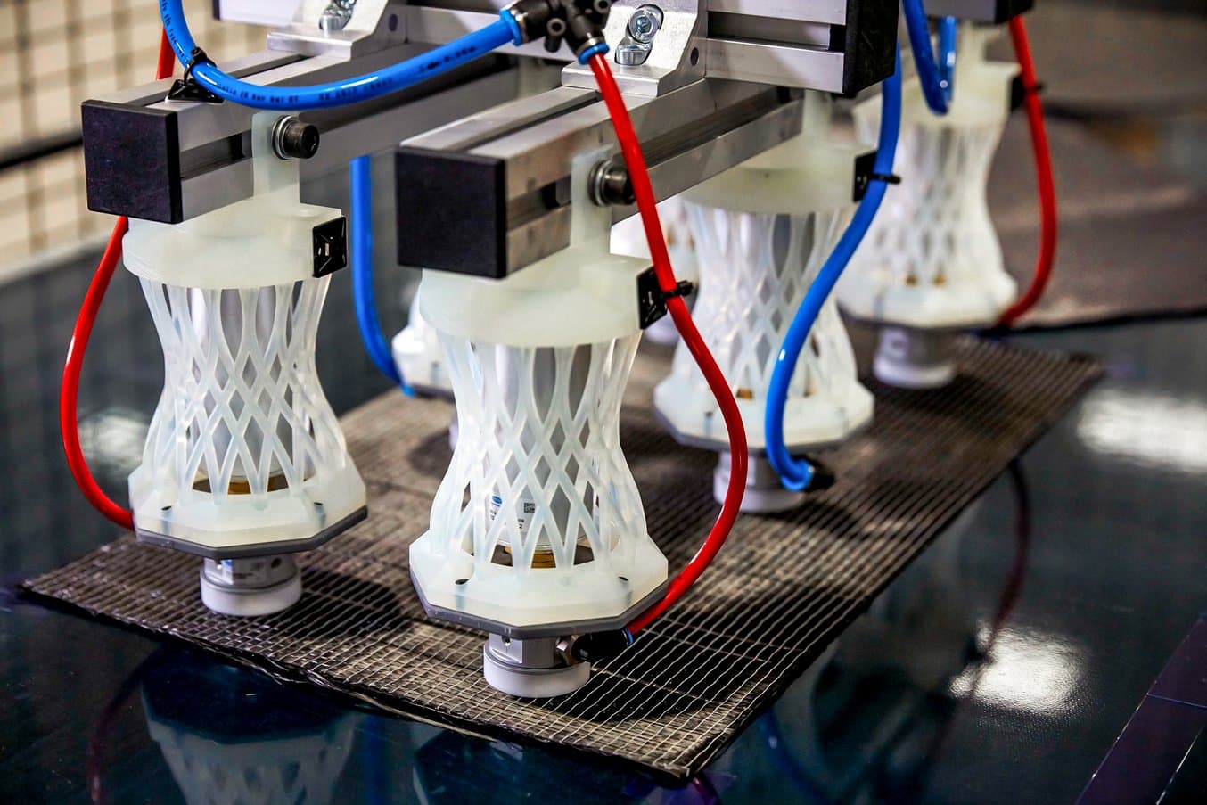
In one current project, researchers are exploring automating moving carbon fiber plies with high accuracy and speed using a pick and place robot. After prolonged use, however, the L-brackets that held the robot’s compressed air grippers started to bend around the joints which lead to failures and forced the researchers to look for a new solution.
Hear from Matthew Williams, the composite technician working on the project, about design challenges he encountered while creating a custom springy component and how the team managed to manufacture five iterations of the intricate design in just a few days with 3D printing.
Watch our interview with composite technician Matthew Williams to see the pick and place robot in operation.
Williams worked with the AMRC’s open-access additive manufacturing station to manufacture the parts they needed. Read our case study to learn how open access to 3D printing can support hundreds of engineers across the site.
The Need for Accuracy in Composites Manufacturing
Composite materials get their strength from the way the fiber strands are woven and laid out in the parts. This allows engineers to meticulously optimize the design depending on how they expect stresses to affect a component, but also makes manufacturing composites a highly complex workflow.
Laying down carbon fiber sheets is generally a manual process, but human interaction introduces some variance as the plies might get deformed or don’t sit properly. Just a few millimeters of misalignment can lead to faulty parts and waste the expensive material.
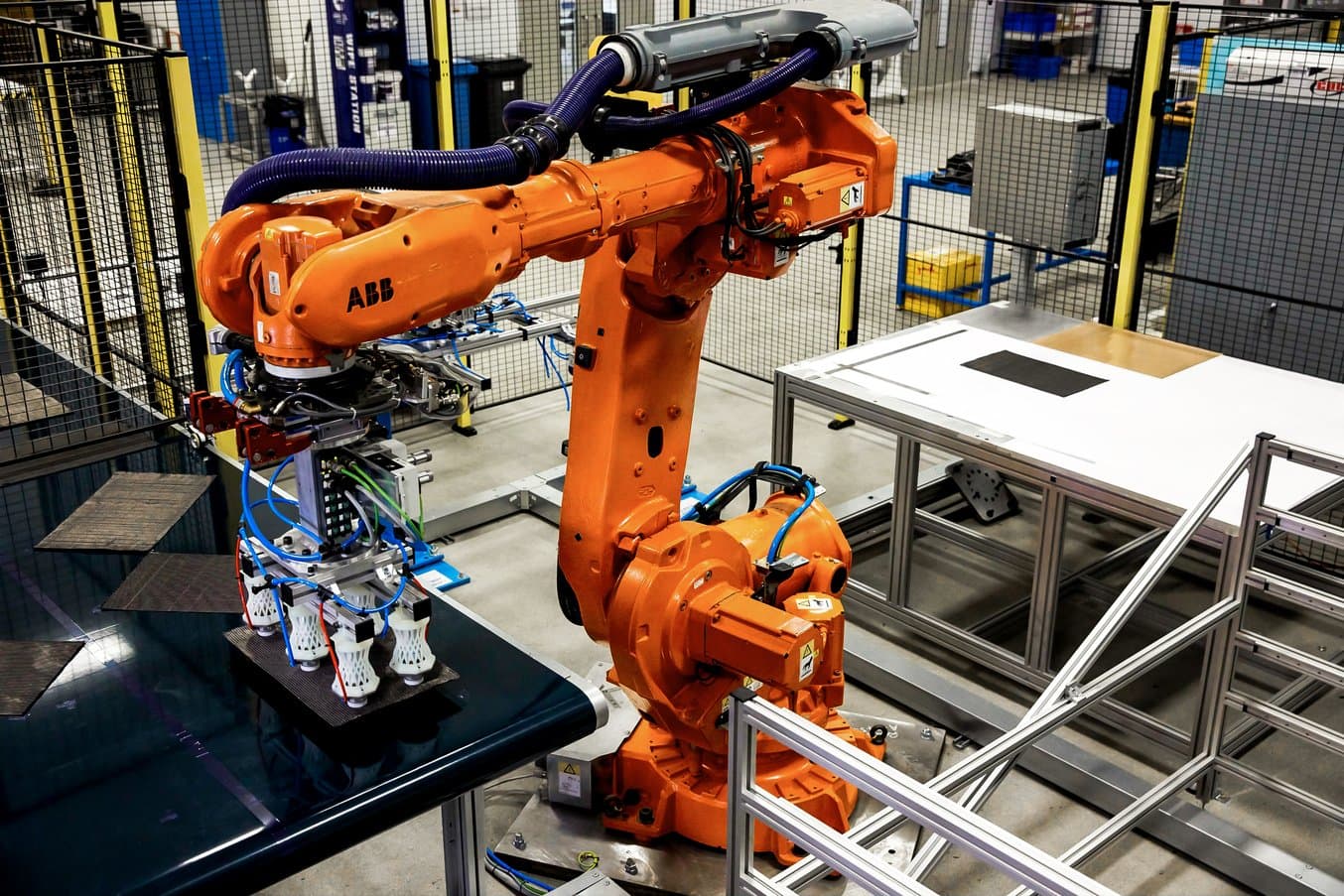
With a pick and place robotic cell designed to create an automated workflow, the researchers are aiming to reduce material waste and increase the speed and accuracy of the process. Precut composite sheets enter the cell on a conveyor belt, where they get picked up by six compressed air grippers that are attached to a 5-axis ABB robot, which then moves the plies and places them, with high accuracy, on top of each other on a table within the cell.
The brackets that initially came with the robot to hold the grippers were aluminum L-brackets fixed to the side of the robot’s end effector. However, as the different pieces of equipment in the cell are not perfectly level, over prolonged use, the brackets started to bend around the joint of the L. Over time, that bend added up such that the gripper wouldn’t pick up the plies from the conveyor anymore.
From a Simple L-Bracket to an Intricate Design
Designing a component with just the right amount of springiness turned out to be a quite complex challenge and Williams had to go through five rounds of iterations.
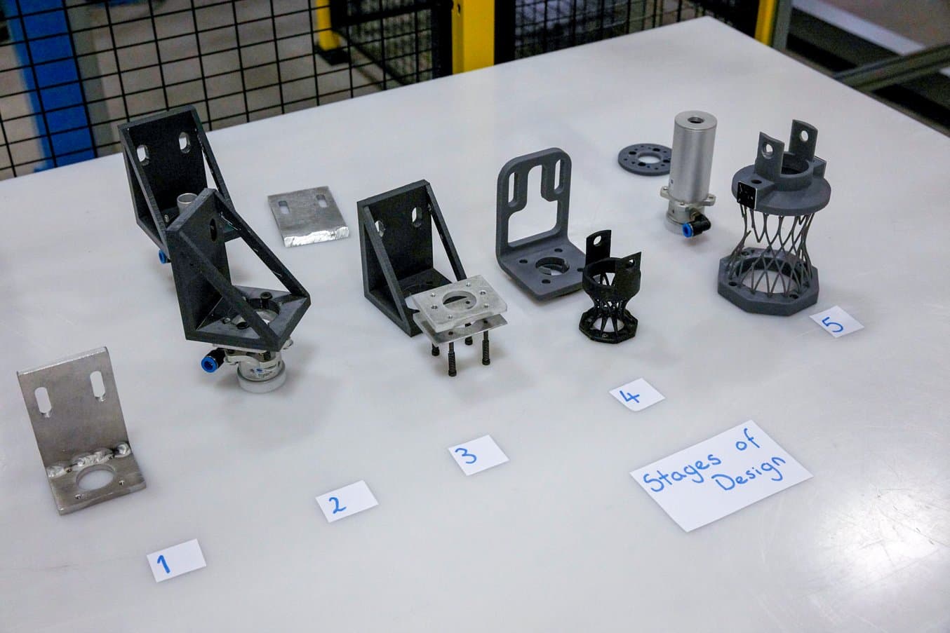
“I started with an aluminum L-bracket that was just two plates that had been tack welded together. Because it's a weld, once it bends, it doesn't really bend back, it just sort of stays bent and deformed. So I turned to plastic because it does bend back when it presses. But that flexed a lot more than aluminum and [the grippers] started splaying fibers out on the table. So we just sort of made the problem worse before it had gotten better,” Williams said.
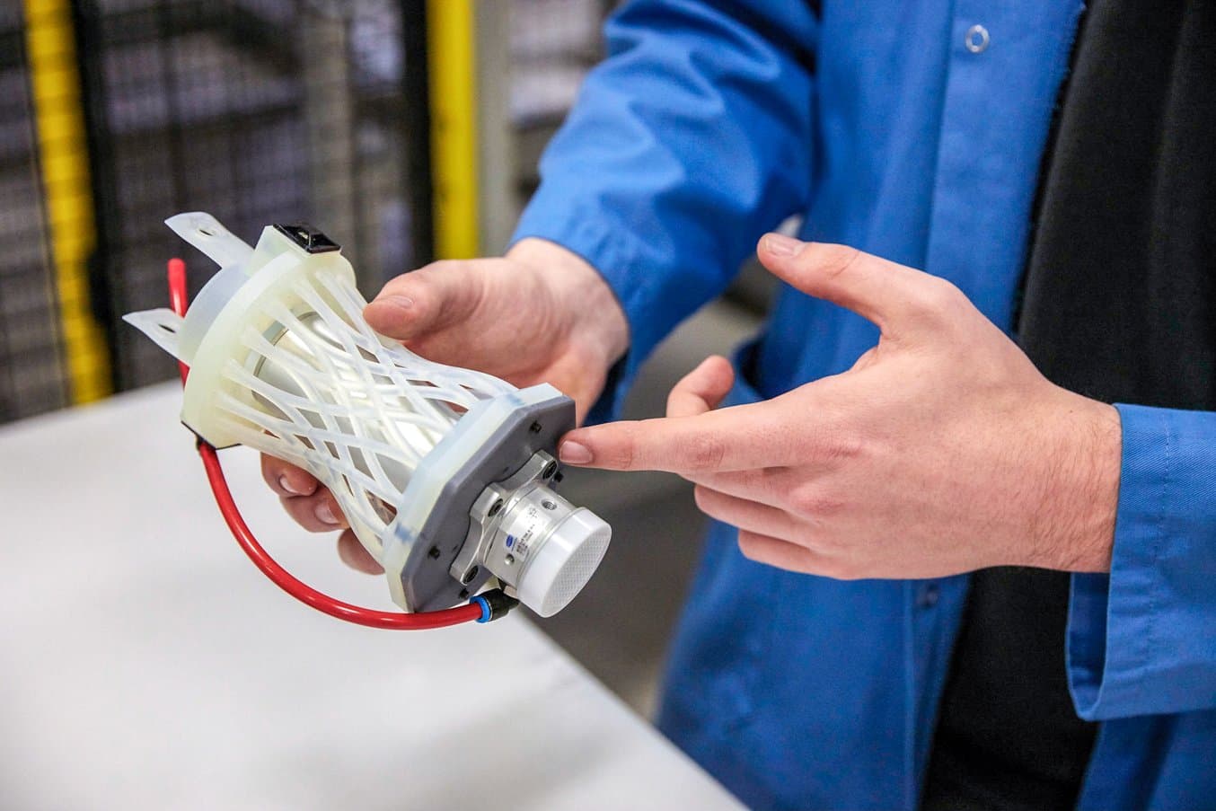
The researcher then decided to switch to a new design. Rather than building off the side of the bracket, the compressed air grippers now sit underneath the bracket. When force is applied from the bottom of the bracket, it doesn’t bend but compacts itself like a spring. As the research progressed, Williams found that the grippers produced too high noise to be safe in a working environment. He needed put a silencer on the grippers, which in turn called for a bigger bracket to house the silencer.
“I thickened up the structure and made it out of more durable material which works a lot better because it even adds to the springiness. It reflexes straight back again and works perfectly,” Williams said.
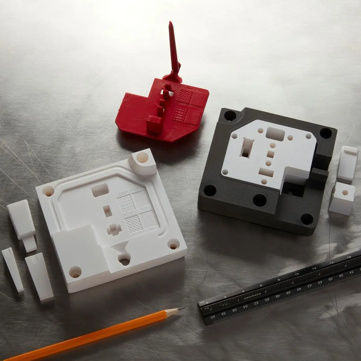
Guide to Rapid Tooling
In this white paper, learn how to combine rapid tooling with traditional manufacturing processes like injection molding, thermoforming, or casting.
Design Freedom and Rapid Iterations With 3D Printing
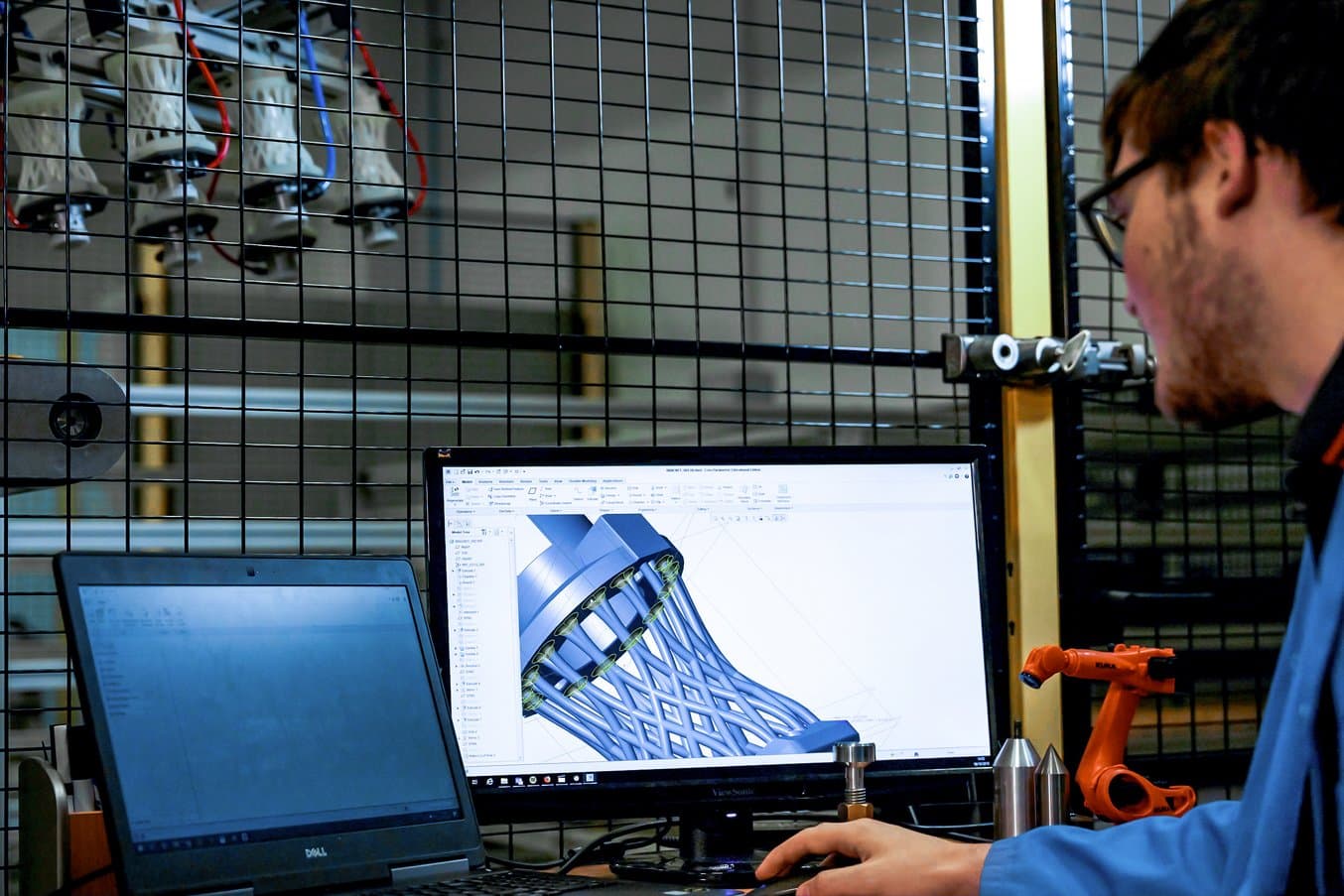
“3D printing gives me more freedom when it comes to creating and designing a part. I can create pretty much any shape and produce it because of how flexible these machines are. It's a lot better when it comes to creating complex shapes like the one I had to make to solve this problem,” Williams said.
3D printing allowed Williams to be more creative and agile in the design process and not be bound by design rules associated with traditional manufacturing methods.
“When you're designing something to be machined, you've got to think about lots of other things like how you're gonna fixture it and how you're gonna get the tool into a certain place. The part is quite complicated on the inside, so the clearance that a tool would need to create the pockets and features from the inside would probably not be sufficient. I'd have to simplify the design or make a new complicated design. It might not work as well, and it would cost more money and take longer,” Williams said.
Having 3D printers in-house also meant that Williams could rapidly go through iterations and save months in lead time throughout the project.
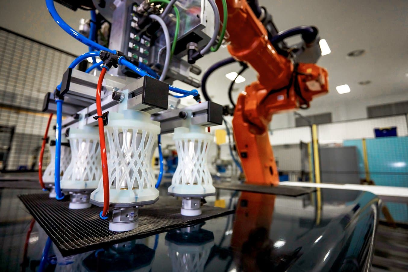
“I've done five iterations of the set of six grippers, which could have taken like 10-15 weeks to machine, and that's without even doing any trials,” Williams said.
“It only takes six hours to 3D print one, and if an iteration doesn't work, I can just create a new design during the day while I'm working. When I go home at night, I can set the printer going, and then it will be done by the morning, so I can work throughout the day with that new part,” Williams said.
Explore How a 3D Printing Station Supports Hundreds of Engineers at AMRC
Williams worked with the Design and Prototyping Group at AMRC to produce the 3D printed parts. The group recently installed a new additive manufacturing station with a fleet of 12 Form 2 stereolithography (SLA) 3D printers that provide open access to 3D printing for all engineers across the site.
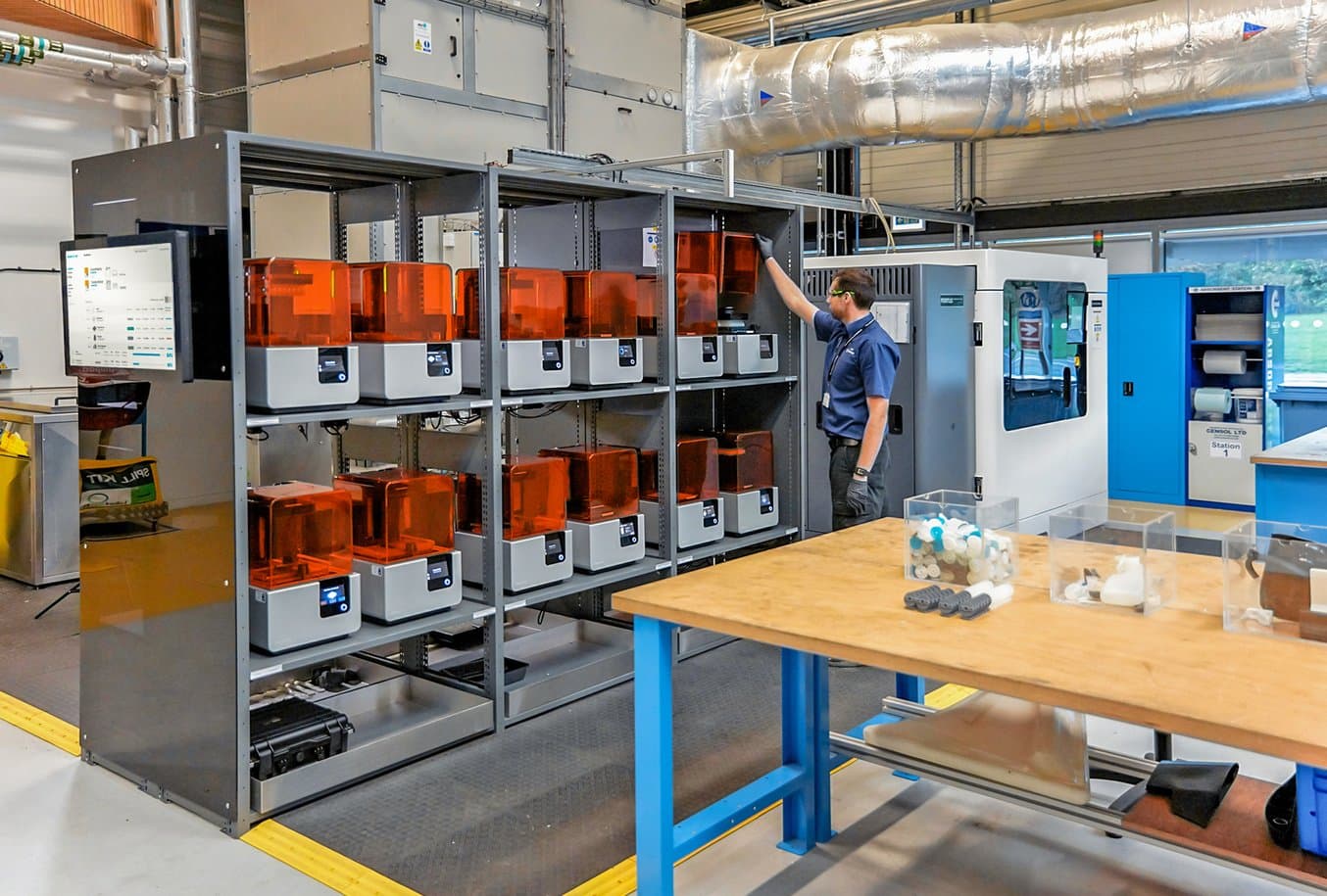
“The fact that we've got [the printers] on the site is absolutely amazing. It saves me so much time because I could just set my prints going, walk across the road when they're finished, take them out of the printer, and then bring them here and employ them straight away. That's a lot faster than having to talk to someone in an external company to get them produced and shipped here,” Williams said.
Learn about the 3D printing station at the AMRC and see other applications like batch 3D printing of 500 high-precision drilling caps for drilling trials for Airbus, a temperature resistant sensor bracket for welding, and custom filament winding rollers for composites manufacturing.
Want to learn more about the printers and technology behind the AMRC’s 3D printing station? Explore Formlabs latest SLA 3D printers, the Form 3 and the large format Form 3L, and Formlabs collection of engineering resins for your own project, or request a free sample 3D printed part to see materials firsthand.
