
Required supplies:
- 2.5 mm hex driver
- Nitrile gloves
- Low-fiber paper towels or disposable microfiber cloth
- Clean isopropyl alcohol (70% or higher)
- PEC*PADs
- Disposable syringes or medicine droppers
- Flashlight

Resin spills can prevent your printer from operating normally, impede troubleshooting and diagnostics, and cause additional damage when shipping or transporting a printer. If you notice that spilled resin has drained into the printer frame or your printer epxeriences issues even after cleaning, you may need to partially disassemble your printer to drain liquid resin.
Use this guide to clean an extensive resin spill in a Form 3 generation printer.
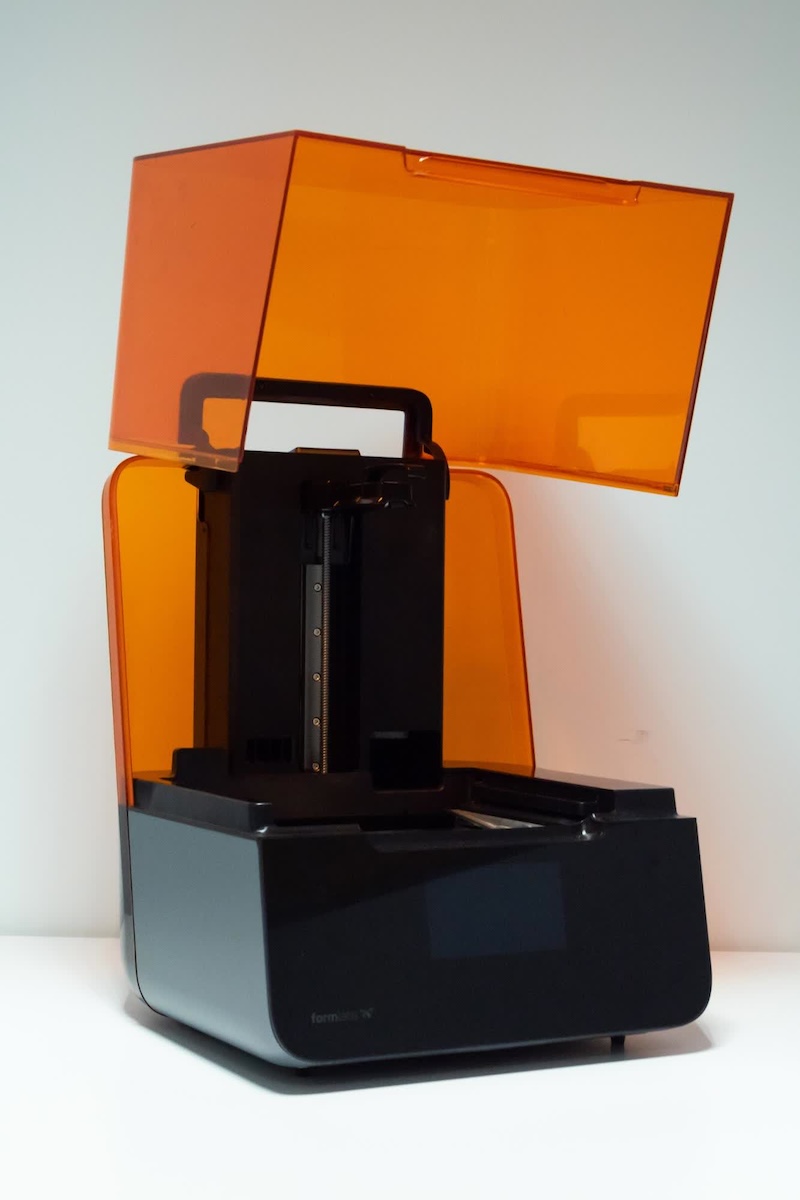
Required supplies:
Estimated time: 30–60 minutes, depending on the extent of the spill
WARNING:
Resin may cause skin irritation or an allergic skin reaction. Wear gloves when handling liquid resin or resin-coated surfaces. Wash skin with plenty of soap and water.
Preparing the workspace
Overview: Prepare the Form 3 and a dust-free workspace for cleaning the resin spill.
Step 1: Remove the build platform
Remove the build platform first to avoid dripping resin onto the LPU or into the printer cavity.
Step 2: Remove the resin cartridge
Remove the resin cartridge and close the vent cap to prevent resin from dripping off the bite valve and into the printer.
Step 3: Remove and store the resin tank
Remove the resin tank, place it in the resin tank carrier, and cover it with its lid. Set the carrier and tank aside on a clean, flat surface.
NOTICE:
Wear gloves and hold the resin tank by the tank grips on either side to avoid contamination or damage to the underside of the tank.
Step 4: Prepare the workspace
Clear a workspace around your printer. Ensure that the workspace is well-ventilated and free of dust. Prepare additional space for storing the display assembly of the printer during maintenance.
Cleaning the printer cavity
Overview: Begin to clean the printer cavity and optical window.
Step 1: Move the LPU to its maintenance position
Tap the wrench icon to access the Settings screen, then tap Maintenance > Motor Moves. The Motor Moves screen appears. Tap and hold Left (<) to move the LPU housing to the middle of the printer cavity. Other controls on this screen fully sweep the LPU housing across the printer cavity and control the build platform carriage.
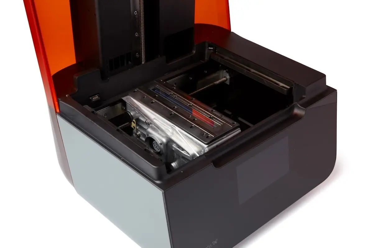
Step 2: Unplug the printer
When prompted by the touchscreen, disconnect the power cable before continuing with maintenance. Do not perform maintenance on the printer while it is connected to power.
WARNING:
Moving parts and lead screws present crushing and tangling hazards. Be sure that the printer is unplugged from its power source and powered down before interacting with the LPU.
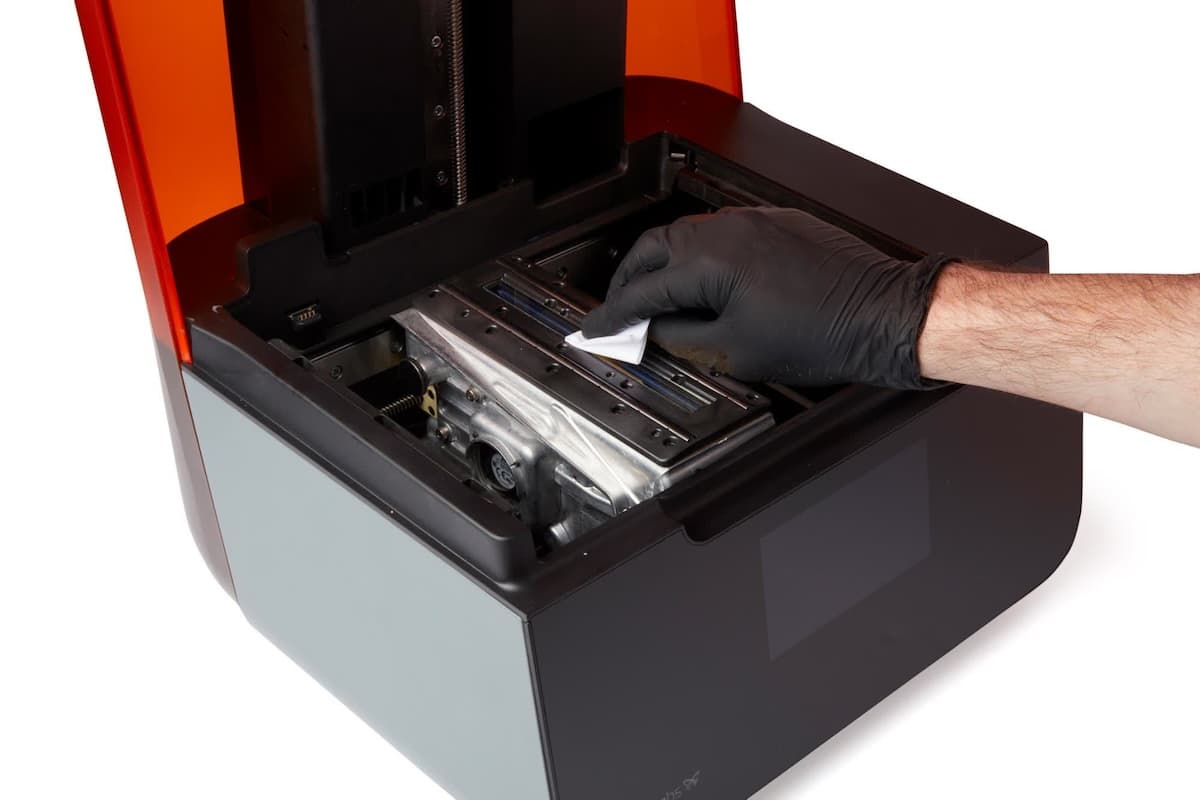
Step 3: Inspect and clean the optical window
Inspect the optical window and the top of the LPU housing for liquid resin. If any liquid resin is present, clean it using a small amount of IPA with a clean microfiber cloth or low-fiber paper towel. Move the cloth slowly to allow the IPA to dissolve the resin. Starting from the far end of the window, wipe slowly, pulling the wipe toward you. Make multiple passes until the entire surface is clean. Allow the surface to dry before using additional IPA with PEC*PADs to wipe the glass surface.
For further information about cleaning the glass optical window, see the support article Cleaning the glass optical window (Form 3/Form 3B).
Step 4: Power on the printer
The LPU must be returned to its home position before continuing with maintenance. Close the printer cover and connect the power cable to the printer and the power supply. The printer will initialize. The LPU will move back to its home position and perform a calibration.
Step 5: Unplug the printer
Once the LPU calibration is complete, disconnect the power cable again before continuing with maintenance. Do not perform maintenance on the printer while it is connected to power. Wait five minutes after disconnecting the printer from power before proceeding.
Step 6: Clean the printer cavity
Open the printer cover. Check inside the printer cavity to ensure that no resin has pooled on the printer floor. Clean any resin inside the printer cavity with paper towels. Dampen the paper towels with isopropyl alcohol if necessary to fully remove the resin. Use a disposable syringe or dropper to remove liquid resin from corners and tight spaces.
DANGER:
IPA is flammable and presents a fire hazard. Keep containers closed, and keep out of the reach of children.
Removing the display assembly
Overview: Unscrew and uninstall the display assembly.
NOTICE:
The Form 3 contains sensitive electronic components. Ground yourself before touching any electronics in the printer by using a grounding strap or touching a grounded piece of metal.
Step 1: Remove the display screws
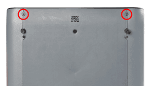
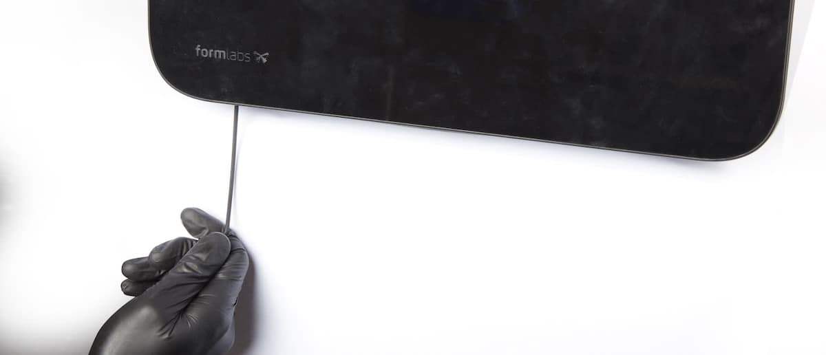
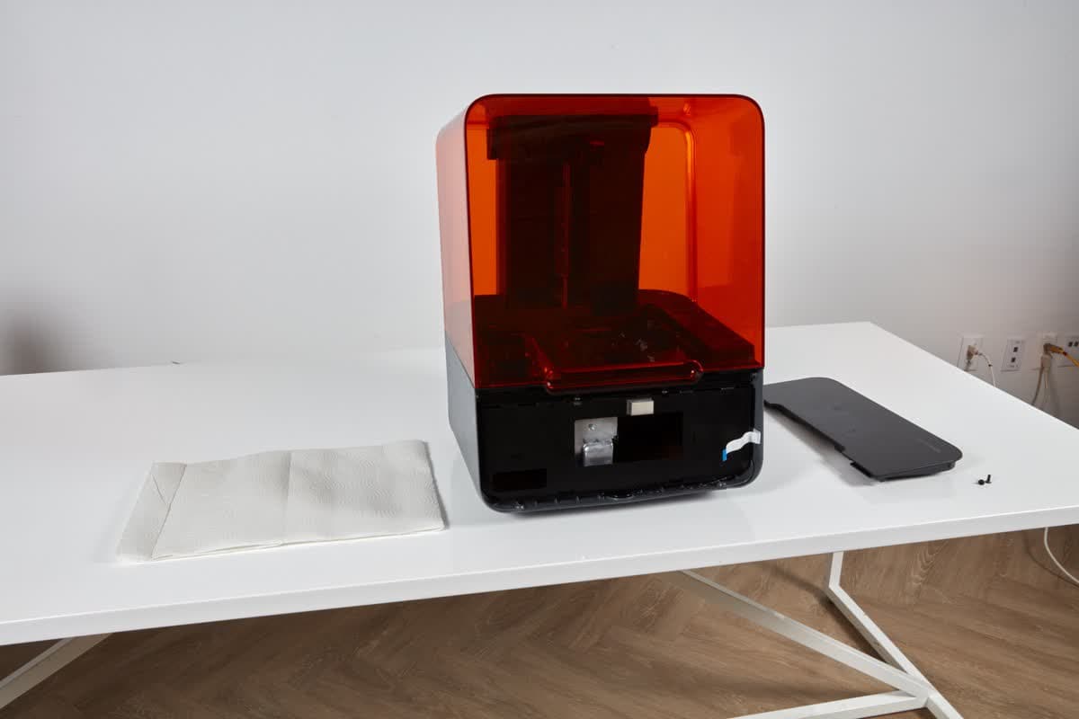
Place the printer at the front of your work surface so that the front edge of the printer overhangs the front edge of the work surface. Locate the two 2.5 mm hex screws at the front of the bottom shell. These screws secure the display to the printer frame. Use a 2.5 mm hex driver to loosen the two screws. Remove the screws and set them aside.
NOTICE:
Once the two display screws are removed, the display assembly is no longer secured to the printer frame. To prevent damage to the display ribbon cable, read the remaining steps in this guide before continuing.
Step 2: Separate the display assembly from the printer frame
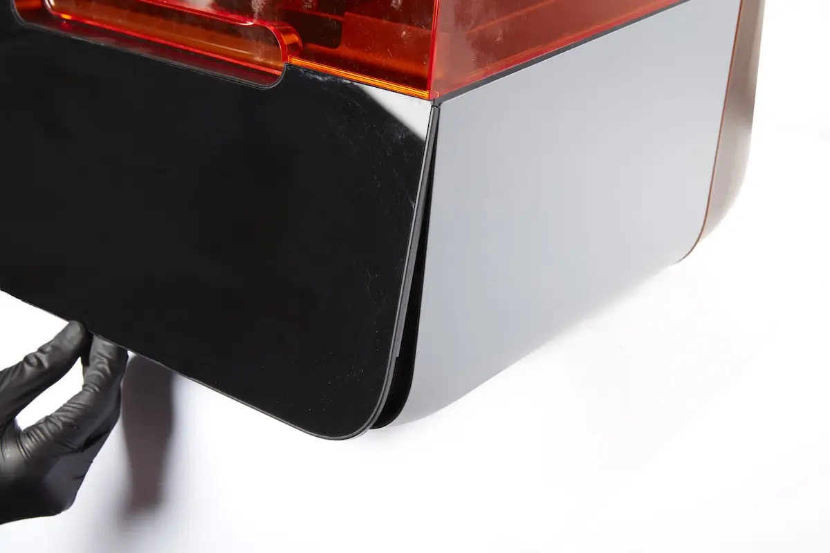
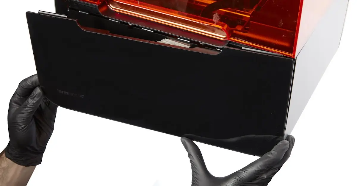
The top of the display assembly is held to the printer frame via a set of plastic tabs. Tilt the bottom of the display assembly slightly away from the printer, then lower the display assembly to separate it from the printer frame.
Step 3: Rotate the display assembly
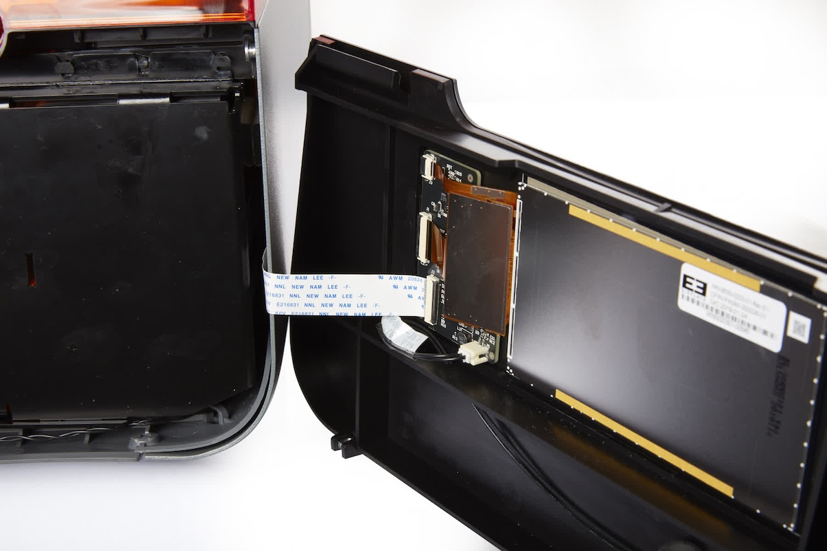
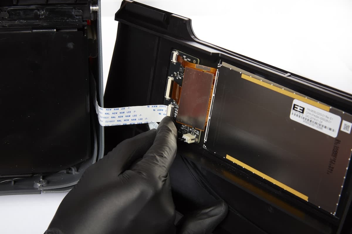
The display ribbon cable connects the display assembly to the printer motherboard. Rotate the display assembly to the right to access the display ribbon cable connector.
NOTICE:
Do not pull on the ribbon cable or pull the display assembly away from the printer. Doing so may damage the display ribbon cable.
The display ribbon cable is secured in the connector with a latch. Lift the latch away from the display assembly to free the display ribbon cable.
Remove the display ribbon cable from the connector and set the display assembly aside.
Draining the printer
Overview: Drain any liquid resin out of the bottom shell of the printer.
Step 1: Prepare the workspace
Place a layer of paper towels or other absorbent material in front of the printer.
Step 2: Drain the printer
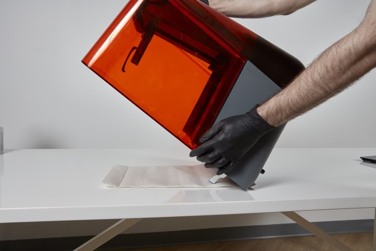
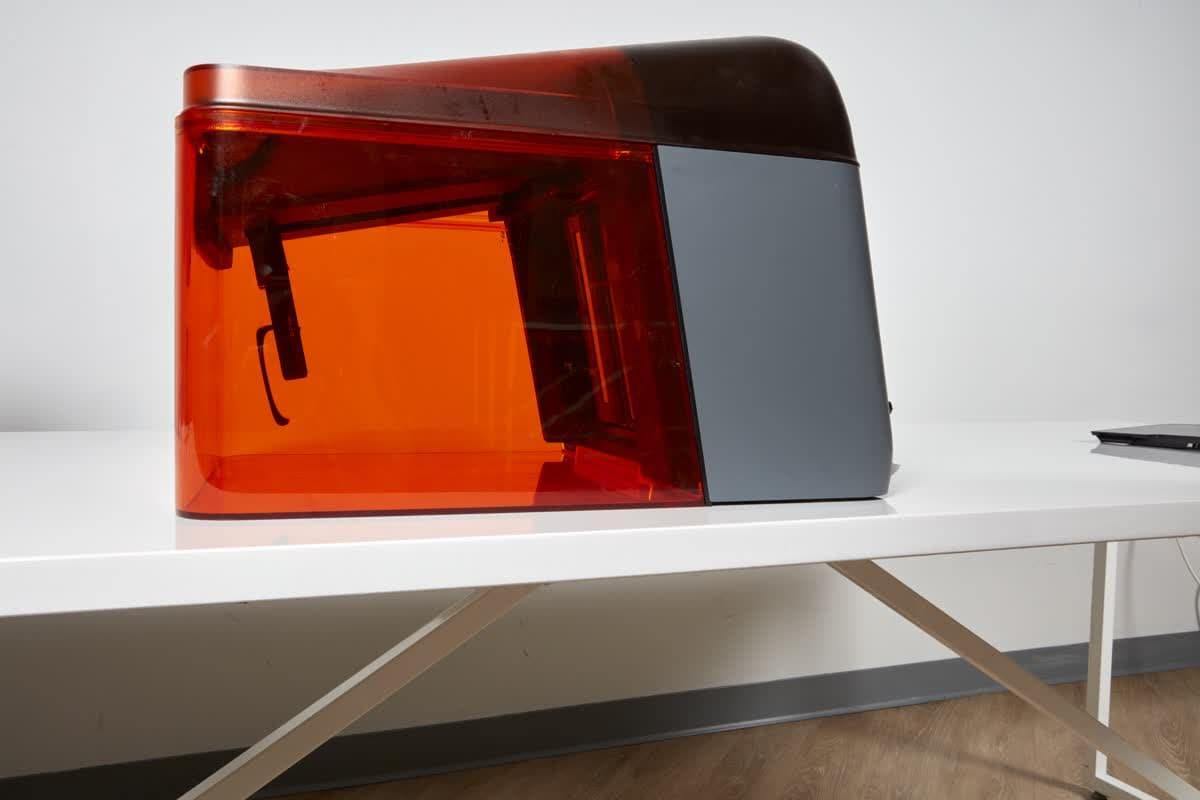
Gently tip the printer forward until it rests face-down on the paper towels. Be sure not to fold or pinch the display ribbon cable and that it is kept away from the paper towels and liquid resin. Leave the printer face-down until it is fully drained.
Step 3: Clean the workspace
Tilt the printer back onto its feet. Collect the paper towels for disposal. Using fresh paper towels, clean any remaining liquid resin on your work surface or the face of the printer.
Always dispose of resin and any supplies contaminated with it according to the SDS. Put the container of soapy water and any soiled paper towels or swabs in a window or other sunny space so that the resin cures in ambient light. Once the resin cures, it can be disposed of with regular household waste.
Reinstalling the display assembly
Overview: Mount and secure the display assembly.
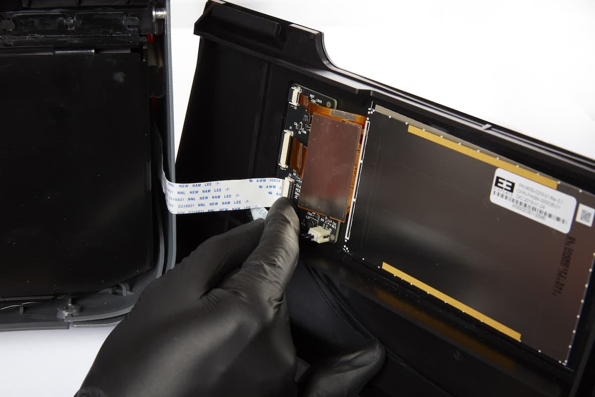
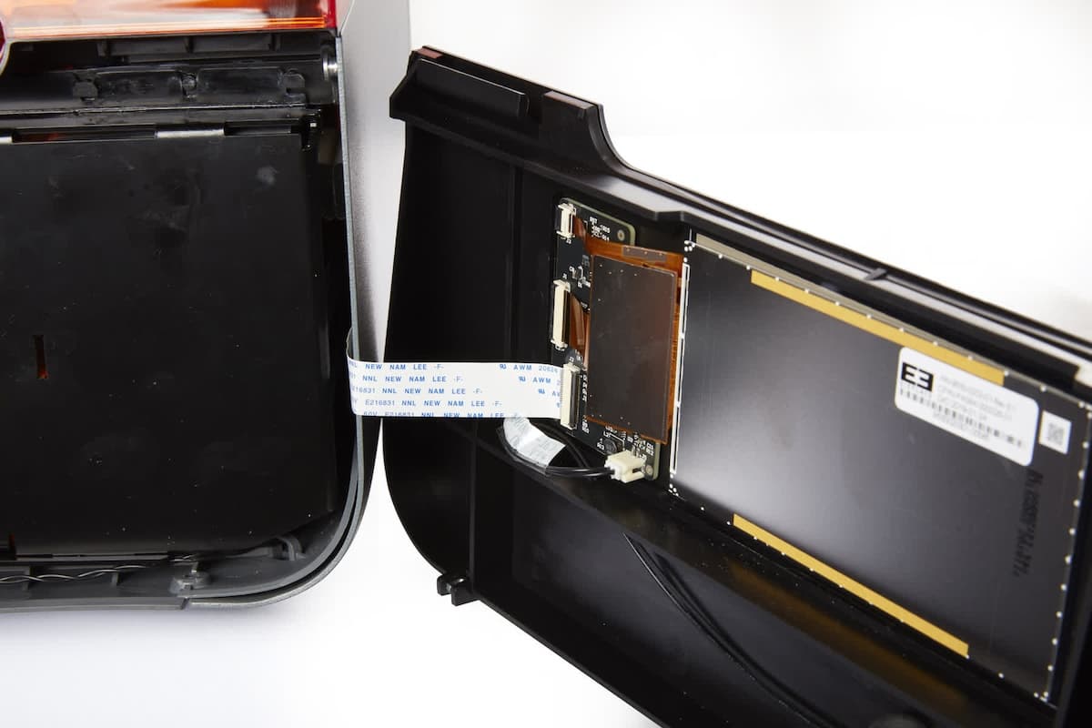
Step 1: Reconnect the display ribbon cable
Insert the display ribbon cable into the connector on the display assembly, ensuring that the ribbon cable is not twisted or folded.
Step 2: Secure the latch
Rotate the latch towards the display assembly to lock the display ribbon cable in place.
Step 3: Install the display assembly
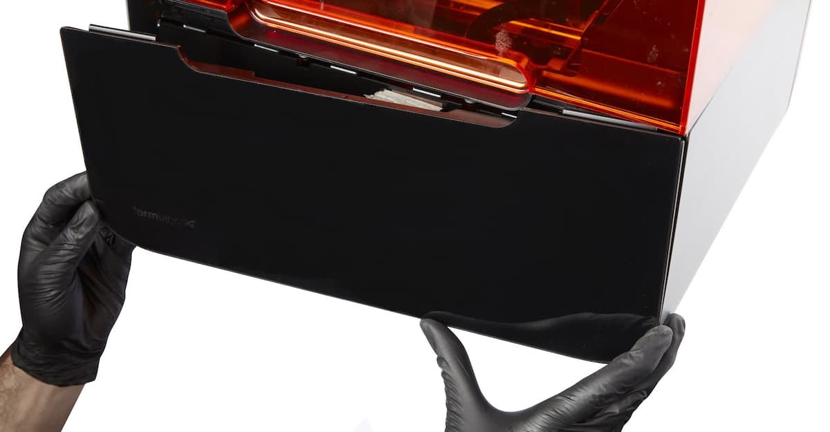
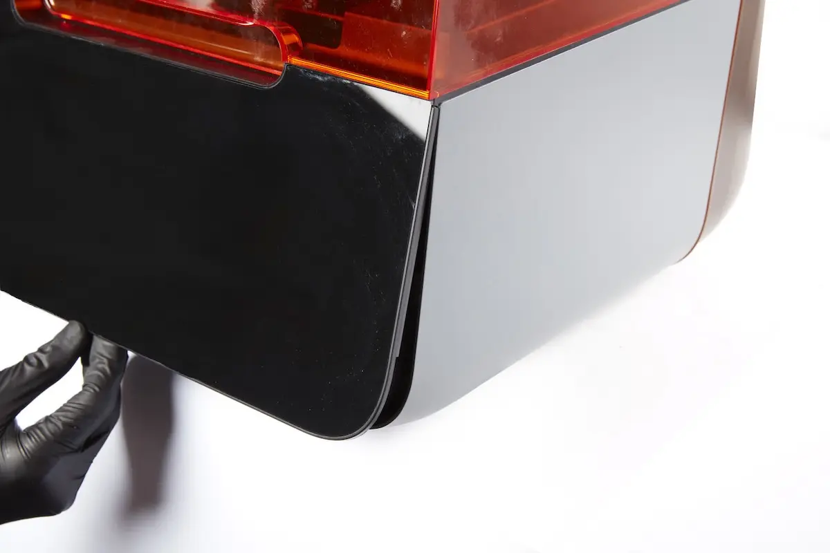
Insert the tabs on the top edge of the display assembly underneath the top shell of the printer. Tilt the bottom edge of the display assembly towards the printer until it lies flush with the bottom shell and side shells. Ensure that the display ribbon cable is not caught between the display assembly and the printer frame.
Step 4: Secure the display assembly
Thread the two 2.5 mm hex screws into the holes at the front of the bottom shell. Use a 2.5 mm hex driver to tighten the screws until snug.
Preparing the printer for shipping (optional)
Overview: If you cleaned your printer in order to ship it safely, pack it according to Formlabs instructions to avoid further damage during shipping.
Step 1: Locate packaging materials
Locate all necessary packaging materials listed in the support article Shipping your Form 3/Form 3B. If the original packaging for the printer is not available, contact Formlabs Support or an authorized reseller to request replacement packaging.
Step 2: Pack the printer for shipping
Pack the printer in the original packaging using instructions in the support article Shipping your Form 3/Form 3B.
NOTICE:
Use the original packaging to avoid further damage to the printer, which can result in additional fees.
Step 3: Affix the shipping label (optional)
Refer to instructions from Formlabs Support or your authorized reseller for shipping policies or labels and know what to expect from the repair or replacement process.
Printing the test print
Overview: If you plan to continue using the printer, power it on and run a test print.
Step 1: Power on the printer
Connect the power cable to the printer and the power supply. The printer will initialize, and the touchscreen will turn on.
Step 2: Download the test print
Download the test print FORM file and open the file in PreForm. Models are available for Clear, Grey, White, and Black Resin. Formlabs recommends printing the optics test with a Standard Resin.
Step 3: Modify the print settings
In the Print Setup window, set the Layer Thickness to be 100 microns with the selected material.
Step 4: Regenerate supports
Open the Supports tool. Click Auto-Generate All to regenerate the supports using default values.
Step 5: Print the test print
Click the orange Print button to send the test print to the printer. Start the job on the printer.
Step 6: Upload diagnostic logs
Once the print is complete, upload diagnostics logs using Formlabs instructions. Formlabs uses diagnostic logs to assess the results of the procedure.
If you are using an authorized reseller, the reseller will contact Formlabs for further diagnostic information.
Step 7: Wash the test print
Wash the test print and allow it to dry while still attached to the build platform.
Step 8: Photograph the test print
Leave the test print parts on the build platform. Variations in print quality across the build area can help Formlabs Support or your authorized reseller locate contamination on the optics.
Take well-lit, in-focus photos and attach them when submitting your support request.
Step 9: Submit a support request
Submit the photos of your test print within a new (or current) support request to Formlabs Support or your authorized reseller, along with the serial name and original order number of your machine.