WHITE PAPER
Formlabs Logo

Preparing models for printing with 3D Packing (SLS)

Preparing models for printing with 3D Packing (SLS)

PreForm allows print jobs to be automatically prepared for Fuse 1 generation printers by using the 3D Packing function. This function automatically finds an optimal position and rotation for models which minimizes the powder used and maximizes packing density. This feature saves large amounts of time and powder over manual print preparation, and can be customized when setting up a print job.

To arrange your models with 3D Packing:

  1. Click Pack on the toolbar to the left of the 3D scene. The Pack panel appears.
  2. Set your desired Model Spacing. Model Spacing lets you select the minimum spacing to preserve between individual models when packing the build volume. No two models will be closer than the selected distance at any stage of the print.
  3. Click Pack All Models. PreForm rotates and translates your models to maximize packing density.

Note:

Models shrink slightly during printing, so you may see some visible gaps between models even when very low model spacing settings are applied. This is because the spacing is applied to the model's larger, mid-print state, before the sintered powder cools and shrinks to its final size displayed in PreForm.

If any models are selected, the 3D Packing feature only packs the selected models and leaves unselected models in their original position. You can also define which models can rotate and move with model locking settings. Read about Locking model orientation (SLS) to learn more.

You can also use the Pack panel to duplicate models and efficiently pack those copies with the Fill Build Chamber and Copy & Fill Gaps tools.

Using the Cage tool

With PreForm version 3.41 or later, use the Cage tool to enclose models inside an automatically generated cage. The feature finds an optimal position and rotation for models inside a generated cage to improve the post-processing experience for batch production of SLS parts.

Group small parts together to simplify post-processing and traceability. The cage is sturdy enough for post-processing with the Fuse Depowdering Kit, the Fuse Blast, and the Fuse Blast Polishing System.

Note:

The Cage tool presets are guidelines. Formlabs recommends experimenting as needed to achieve your desired results.

To enclose models in a cage:

  1. Update PreForm to version 3.41 or later.
  2. Select the models you wish to enclose in the cage.
  3. Click Cage on the toolbar to the left of the 3D scene. The Cage panel appears.
  4. Set your desired settings for the cage.
    1. Cage Label: Click the checkbox to add a label to the cage and enter the name of the label you wish to assign to the cage. The name is engraved on a plaque in a corner of the cage.
    2. Packing Settings:
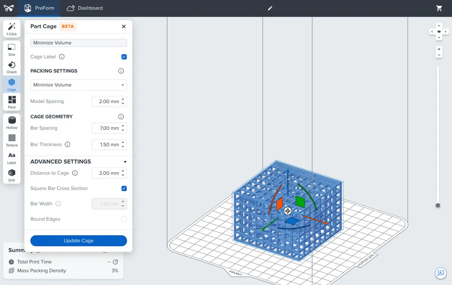
      • Minimize Volume generates a cage that minimizes the total volume. Cages generated with this option generally tumble better in the Fuse Blast than those generated with the Minimize Height option because of the rectangular cage shape.
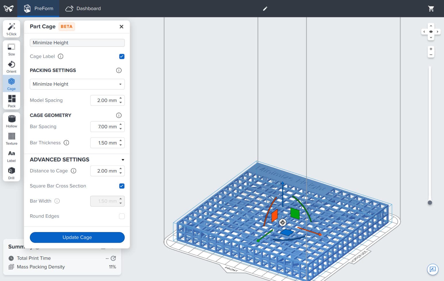
      • Minimize Height generates a cage that minimizes the height for a faster print.
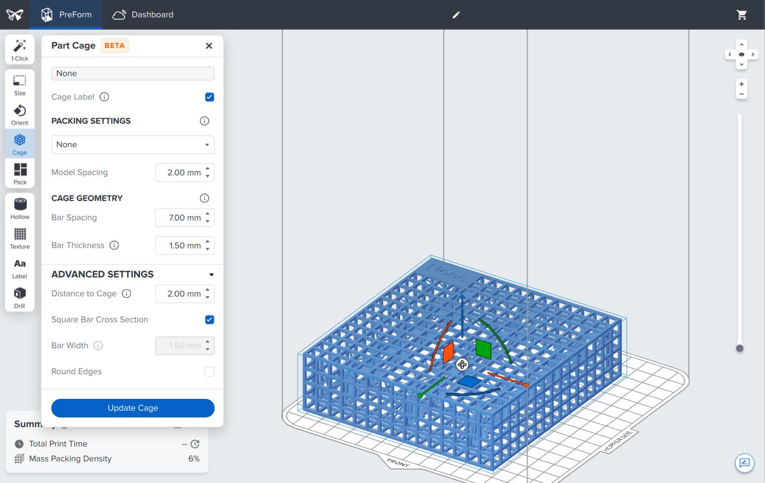
      • None generates a cage with no packing optimizations, letting you manually pack your parts while using part cages.
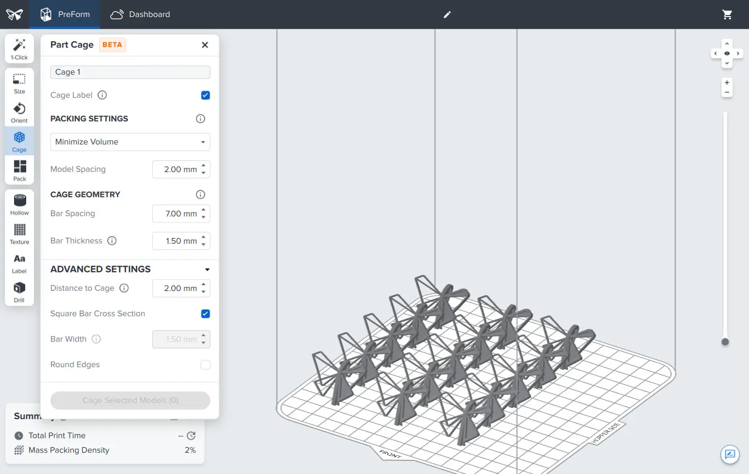
3D scene with models.
Models enclosed in a cage with the Minimize Volume setting.

3D scene with models.

Models enclosed in a cage with the Minimize Volume setting.

Models enclosed in a cage with the Minimize Height setting.
Models enclosed in a cage with the None setting.

Models enclosed in a cage with the Minimize Height setting.

Models enclosed in a cage with the None setting.

  1. Model Spacing: Set the distance between models inside the cage.
  2. Bar Spacing: Select the desired width of the opening between the cage bars. A higher value increases the size of the opening. Ensure that the opening is smaller than any of the parts.

Note:

If you are planning to clean the printed parts while still in the cage in the Fuse Blast, increase the Bar Spacing to above 2.0 mm to prevent blasting media from getting stuck in the cage.

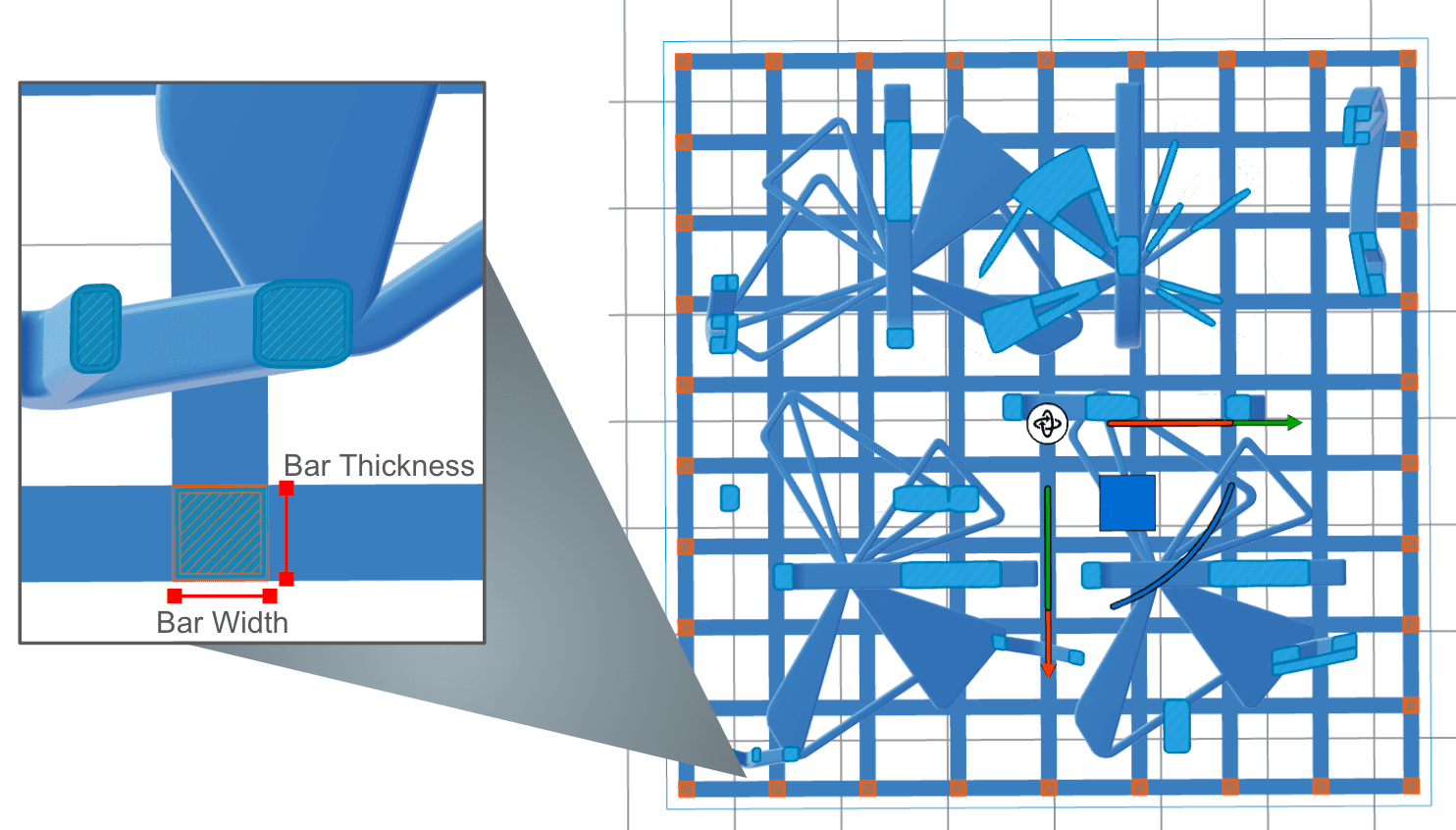
  1. Bar Thickness: Select the desired thickness of the cage bars. A higher value increases the sturdiness of the cage but may increase post-processing time.
  2. Distance to Cage: Select the space left between the models and the cage.
  3. Square Bar Cross Section: Disable this option to set the Bar Thickness and Bar Width to different values. This lets you customize your cage and balance strength with open space for cleaning.
  4. Bar Width: Select the width of the cage bars. This option is only available when Square Bar Cross Section is turned off. If Square Bar Cross Section is enabled, the Bar Width always matches the Bar Thickness.
Bar width and bar thickness.
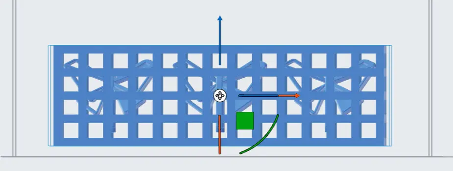
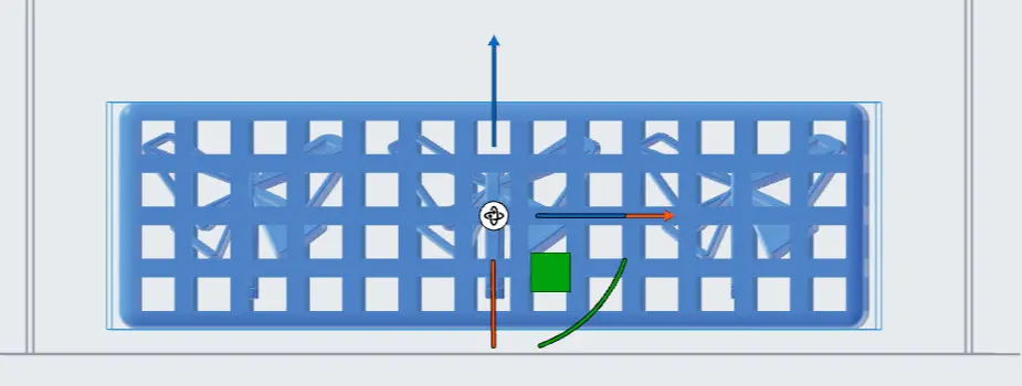
  • Round Edges: Select this option to round the external edges of the cage.
Part cage with straight edges.
Part cage with round edges.

Part cage with straight edges.

Part cage with round edges.

  • Click Cage Selected Models. PreForm encloses, rotates, and translates your models to match the selected values. The selected models are collapsed into a single cage entry in the Model List.

Editing cages

Cages can be renamed or deleted by selecting them from the Model List.

  1. Select the cage in the 3D scene.
  2. Click Cage on the toolbar to the left of the 3D scene. The Cage panel appears.
  3. Edit the cage values.
  4. Click Update Cage. PreForm updates the cage according to the selected changes.

Removing parts from a printed cage

To remove parts from a printed cage, wait for the build chamber to cool before extracting the printed cage from the powder cake.

Clean and media blast the printed parts while still in the cage with the Fuse Blast or Fuse Blast Polishing System. Once the parts are clean, break open the cage with pliers or a small saw, taking care to avoid shards. Continue to post-process parts as needed.