

Desktop Millifluidics With SLA 3D Printing
This report delves into the implementation of millifluidic geometries using stereolithography (SLA) 3D printing. SLA printing enables chip geometries not possible with traditional lithographic techniques, which rely on laminated layers of 2D devices. 3D printed chips offer improved performance, while reducing the cost of customized design.
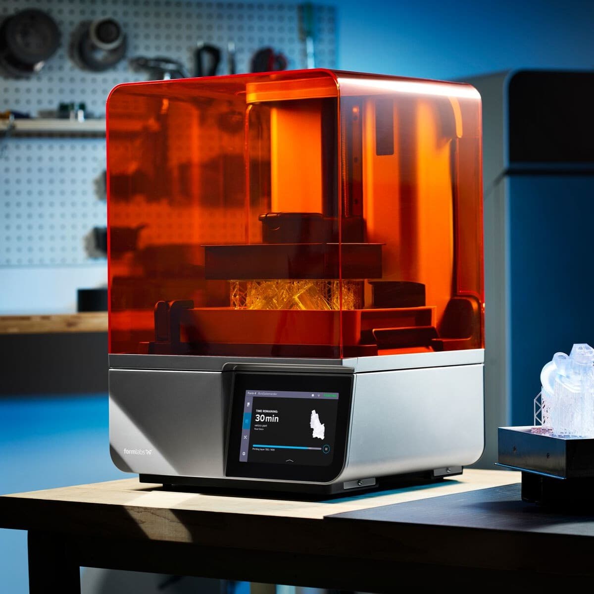
Read on to learn best practices for fabricating millifluidic chips in-house on the Form 4 SLA 3D printer, with example prints and test results. The report outlines best practices, design considerations, and unique applications.
Desktop Millifluidics With SLA 3D Printing
Download as PDFThis report delves into the implementation of millifluidic geometries using stereolithography (SLA) 3D printing. SLA printing enables chip geometries not possible with traditional lithographic techniques, which rely on laminated layers of 2D devices. 3D printed chips offer improved performance, while reducing the cost of customized design.
Read on to learn best practices for fabricating millifluidic chips in-house on the Form 4 SLA 3D printer, with example prints and test results. The report outlines best practices, design considerations, and unique applications.
Introduction
With their high accuracy and ability to produce watertight parts, resin 3D printers are on the leading edge of a new way to fabricate miniaturized fluid transport systems, known as millifluidics. Complex chips of networked channels smaller than a millimeter in diameter are designed to efficiently mix fluids, separate suspended materials, and many other functions within experimental scientific equipment. Millifluidic chips have applications in biotechnology, chemical engineering, and pharmaceutical engineering. This also makes them vital for educational institutions training the next generation of scientists and doctors.
Globally, most millifluidic channels are manufactured using lithography masking, where troughs are selectively etched onto glass plates in a 2.5D pattern. Outsourcing the custom fabrication of fluidic designs using this process typically comes at a high cost (bringing a traditional photolithographic technique into your own lab is also costly) that is not always economical or time efficient. Additive manufacturing offers a solution for rapidly producing functional millifluidic chips on demand. Without any additional cost for complexity, a custom chip can be made at the same cost as a generalized one. With an SLA 3D printer from Formlabs, chips can be manufactured as needed and in only a few hours, removing the need of dealing with bulk purchases and shipping times.
The Formlabs resin library has specific material solutions for many of the fields that implement millifluidics with a selection of biocompatible, temperature resistant, and optically clear resins.
Microfluidics is another term used for these applications, but it refers to smaller sized channels than covered in this report.
Book a Consultation
Get in touch with our 3D printing experts for a 1:1 consultation to find the right solution for your business, receive ROI analyses, test prints, and more.
Millifluidics With SLA 3D Printing
Critical Properties of a Chip Material
Across all fields that implement millifluidic workflows, there are certain properties of a chip material that are necessary to conduct useful experiments.
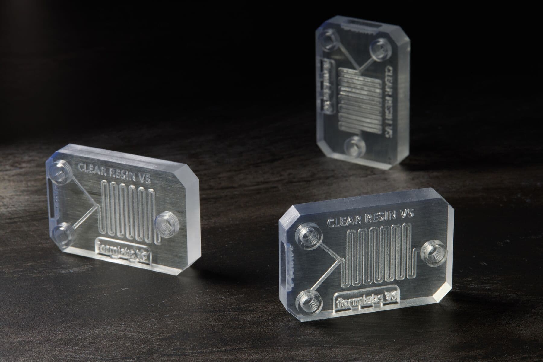
- Optical clarity enables visual confirmation and assessment of fluid behavior and channel performance. Internally, the material must be optically clear, and the surface should be easily polished. Form 4 Series 3D printers print incredibility translucent parts in Clear Resin, which guarantees visibility into the mixing channels.
- Biocompatibility is an important factor in biology and medicine, where a chip needs to be inert and non-toxic. BioMed Clear Resin is a clear biocompatible material that can be printed with Formlabs SLA 3D printers and used for millifluidic chips.
- High precision is a necessity to render sub-millimeter channels embedded in a chip. Certain types of 3D printing, and even low-end SLA printers, are often not capable of printing sub-millimeter channels. Even of capable devices such as a Formlabs SLA printer, print orientation can be vital to guarantee channels do not cure solid.
- Tough enough to withstand connecting and disconnecting standard connector hardware. Dozens of different systems and platforms exist for conducting millifluidic research, which also means dozens of different adapters and connectors. Ensuring that the correct chips are purchased with the right connector for your setup is frustrating and potentially limits which chips you can use. By printing your own chips, you can design your own connector and ensure any design you make will interface with your system.
Optical clarity can be achieved on certain printers with certain resins, including Form 4 Series 3D printers and Clear Resin.
Benefits of 3D Printed Chip Fabrication
Additive manufacturing provides a number of benefits over traditional chip production methods. The first and most significant is cost savings associated with in-house 3D printing. Getting a custom-made millifluidic chip normally incurs an exorbitantly high cost and can take up to two months before having a prototype in-hand. Instead, SLA 3D printers can print any geometry needed right in your lab and have it ready in hours, not months.
Standard etched-glass millifluidic chips that perform basic functions can cost $70 or more. But in many situations, 3D printing can cost an order of magnitude less. Print one millifluidic chip on Form 4 in ~1 h 20 min (depending on size and orientation) with 24.86 mL of Clear Resin. For thinner and smaller parts, print times will be even lower.
|
TECHNOLOGY |
COST PER PART |
LEAD TIME |
|
SLA |
~$2* |
<2 h including post-processing |
|
Lithography |
$73.75 |
2+ days |
*Cost of materials per part if using Clear Resin V5. Bulk materials pricing is available and can decrease the cost per part.
Print Highly Precise Parts With 99% Print Reliability
Millifluidic chips require precision. Form 4 delivers a 50 µm XY resolution with parts that have with ±0.15% XY dimensional tolerances, with consistency across the build platform.
Having a reliable method of production ensures millifluidic chips are produced on the timelines you need and to the specifications you require. A failed print can mean disruptions to work, wasting time and resources. In tests by a an independent global leader in product testing, Form 4 was measured to have a 98.7% print success rate, while the benchmark printers tested have 10x-20x the failure rate of Form 4. For professionals who require parts to be printed reliably, accurately, and without manual labor overhead, reliability matters, and Form 4 can save in resin and consumables, time, and labor, as well as headaches and missed deadlines.
Test Part Results
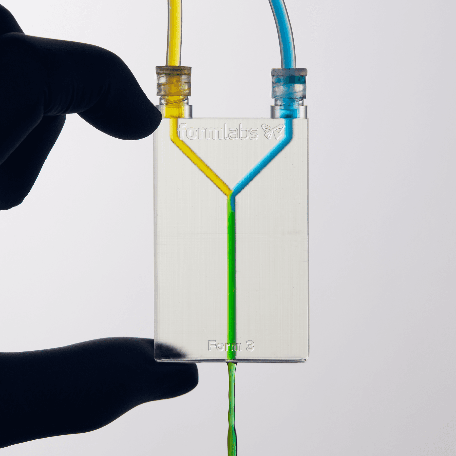
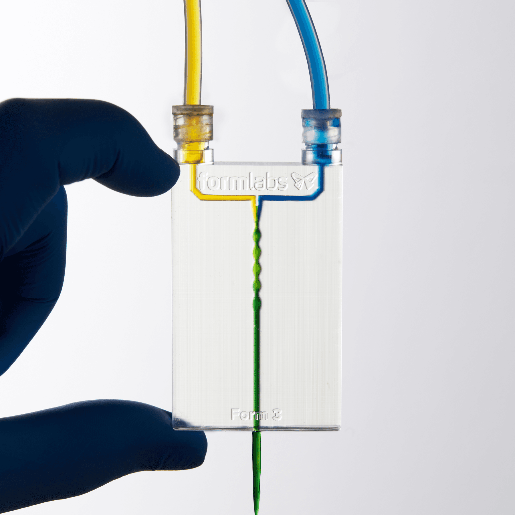
The Formlabs Engineering team designed, printed, and tested two basic millifluidic geometries. Mixers were tested using standard food dye dissolved in tap water. One syringe was filled with yellow, the other blue. Each color was injected into a mixing port. Then the mix was projected onto a white surface where the uniformity of the mix could be observed.
In this experiment, laminar vs. turbulent flow can be observed. In narrow channels, the colored liquids tend to flow side by side, via laminar flow, in the direction of the channel; mixing gradually occurs due to diffusion of the pigment. As the channel cross section increases, eddies and currents running perpendicular to the channel cause chaotic or turbulent mixing.
In our experiments, we found that different mixer geometries influenced the mode of fluid mixing.
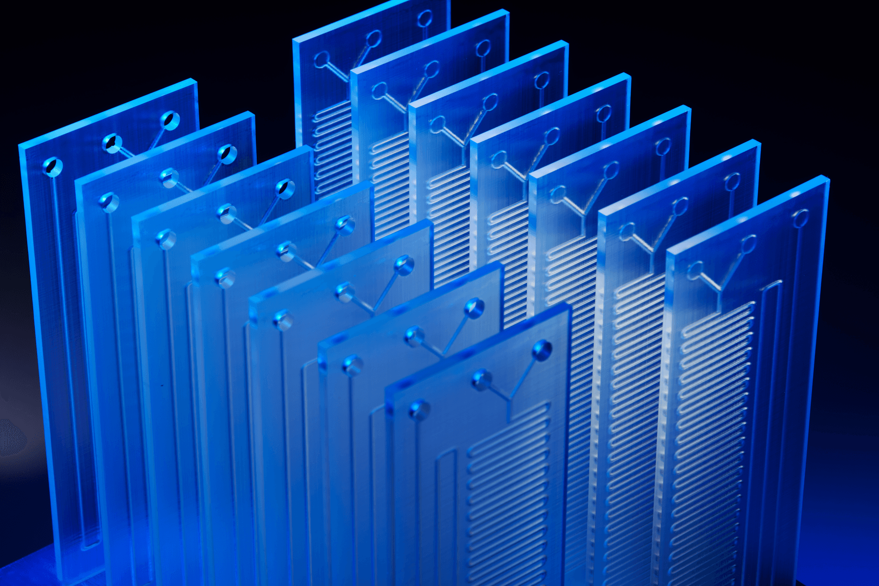
Y-Mixers
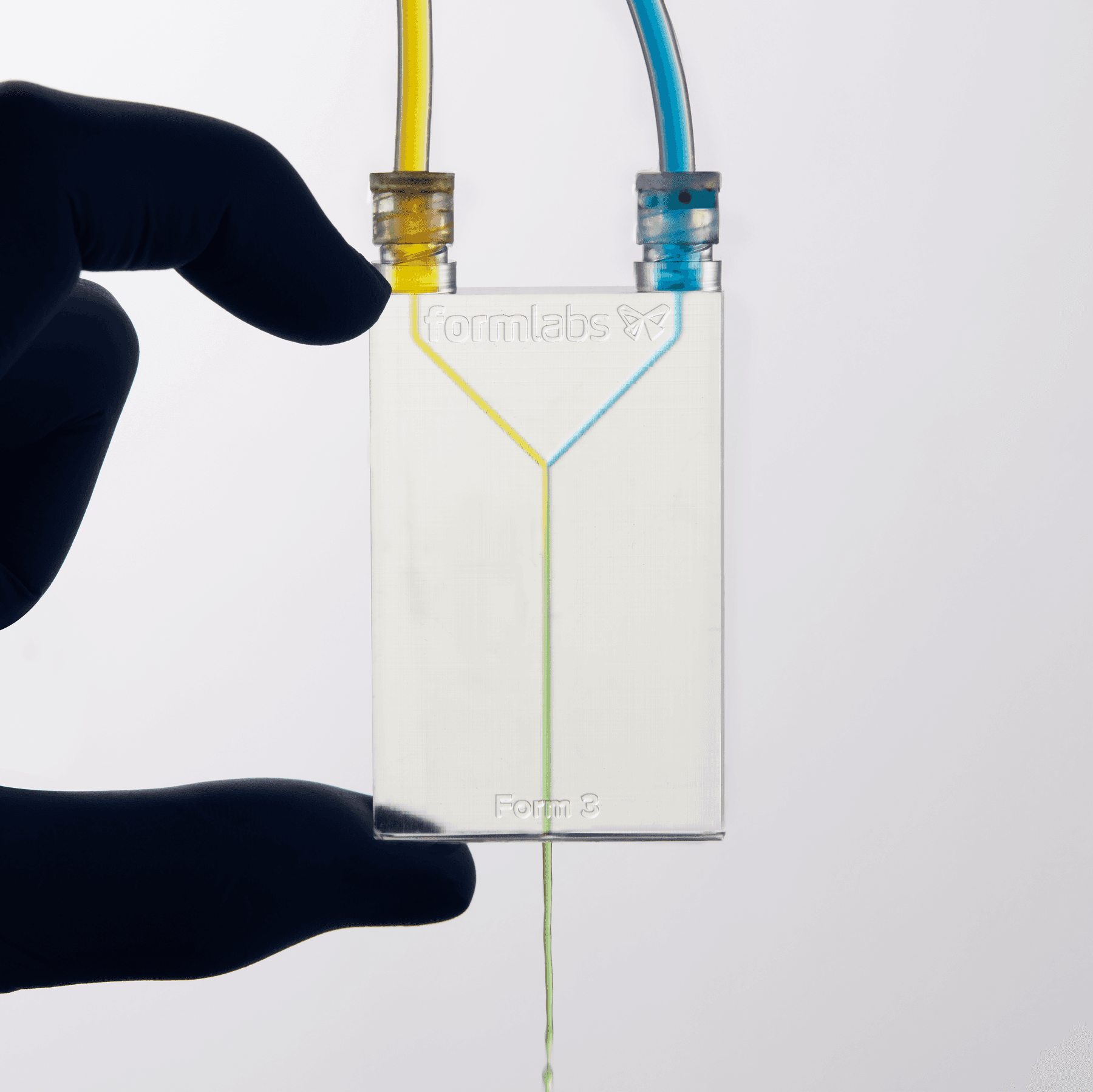
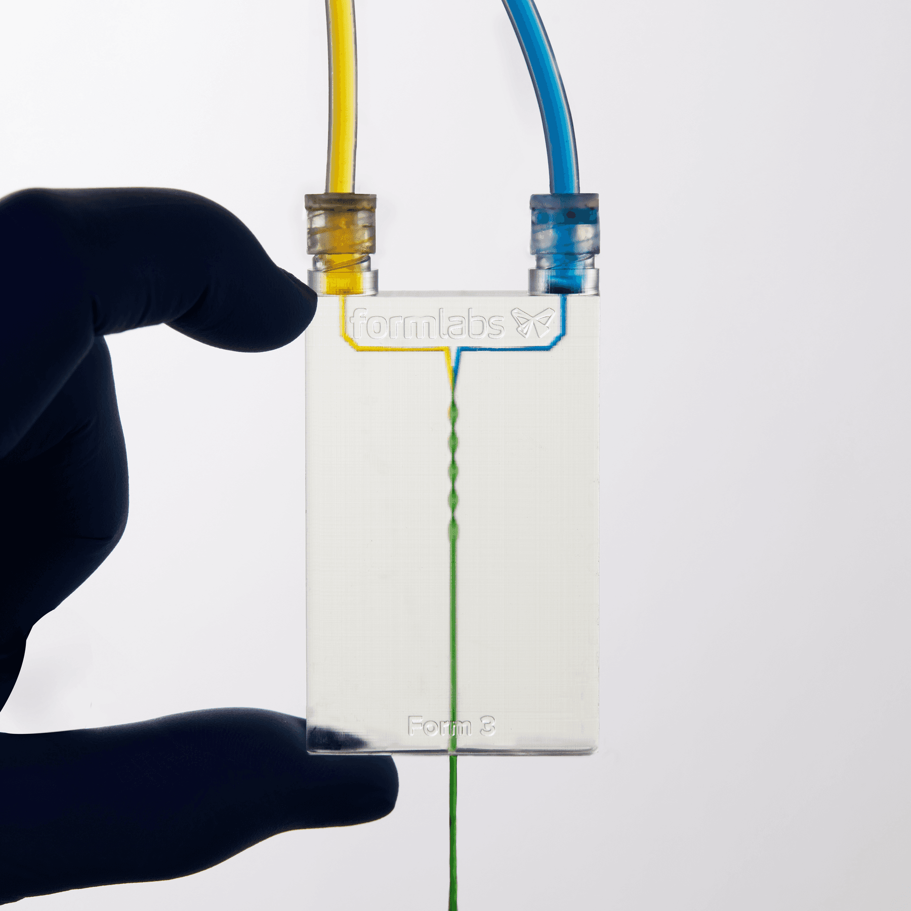
Both the large and small channel Y-mixer produced excellent results, with both liquids adequately mixing. The food dye allows us to see when, where, and how thoroughly the liquids in the channel mix.
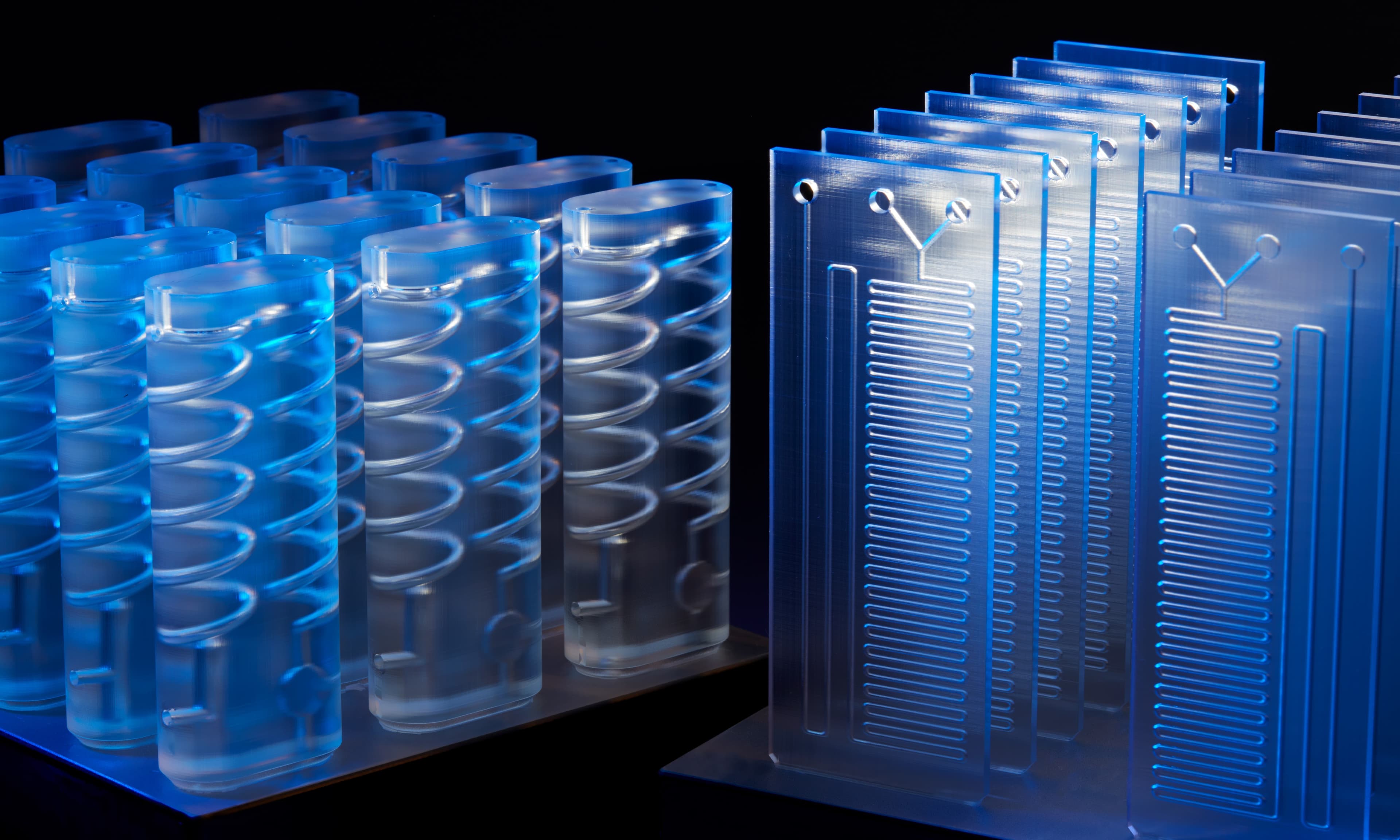
On the left, a Y-mixer with 2.5 mm channels. On the right, a Y-mixer with 1.1 mm channels.
In both Y-mixers, the channels were clear, and fluid mixed as desired. The wide channels caused liquids to mix immediately, producing a thoroughly mixed green fluid. The thinner channel version caused a more gradual mixing of the two liquids. Mixing models can easily be made shorter or longer, and have the channel sized changed, depending on the results desired.
Both Y-mixers were printed upright directly on the build platform. After removing the build platform from the printer, isopropyl alcohol (IPA) was pumped directly through the channels. Then, the parts were removed from the build platforms and washed for 10 minutes in a Form Wash.
This process guaranteed at least half of the prints were successful and were able to mix liquid. We recommend printing at least two models of any chip to guarantee a successful print.
3D Channels
3D channels highlight a unique and powerful feature of 3D printing in-house millifluidic models. Sharp 3D features disrupt laminar flow in narrow channels and allow the designer to control when and how fluids mix.
Design Features
When creating your own chips in-house, there are a few design tips to be aware of.
Efficient Mixers
In 3D printed millifluidic chips, channels can take any three-dimensional path. By comparison, etched glass channels are restricted to a two-dimensional plane and a rectangular cross-sectional shape.
Due to the low cost of printing a single chip, in-house millifluidic prints present the opportunity to experiment with 3D channels.
Embossed Labels
Differentiating between prototype revisions by eye can be a challenge when features are very small, which means that labeling is crucial. The possibility of mixing up different versions of chips and not being able to easily tell them apart is real, potentially costing significant engineering time. If labels are integrated directly into the print, ambiguity and error can be reduced. Labels can be embossed directly in PreForm, Formlabs' free print preparation software. Learn more about adding embossed labels here.
Connectors
Regardless of the existing millifluidics system you have, custom connectors can be printed directly into the chip itself, eliminating the need for adhesives and binders which risk delamination during use. Provided correct tolerancing and design considerations, these connectors can last hundreds of connecting cycles with your system.
Standardized fluid transfer connectors are mainly used in the medical field. Syringes can be found with common connectors which are useful for testing chips manually. For non-standard connectors, a 3D scanner can pull the design into your CAD software, and then easily touched up and printed.
Many millifluidic chip systems implement a clamp in conjunction with an O-ring to connect to chips with an open port on the top surface of the chip. 3D printed chips can easily mimic this port style to interface with those existing systems, and even create added geometry to the port face to better receive the O-ring and clamping head.
Channel Cross Section
With the full geometric freedom that comes with 3D printing, millifluidic chip designers have the ability to create any three-dimensional channel shape with no added cost.
Testing shows that circular channels consistently resolve with a 700 μm diameter, and optimal chip designs can see good results at 500 μm. Following suggested post-processing procedures will help prevent residual liquid resin in the channels from curing.
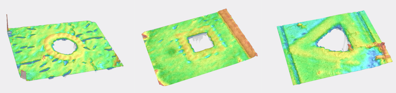
Channel cross-sectional shapes. Circular profiles are most likely to resolve in more orientations compared to other profile shapes.
Further testing shows that channels with a circular profile will be much more likely to print correctly than channels with sharp edges and tight corners, such as triangular cross sections. When designing your chips for SLA, try to keep your channels as circular as possible at small diameters. If a unique profile is needed, print larger to ensure success.
Request a Free Sample Part
See and feel Formlabs quality firsthand. We’ll ship a free 3D printed sample part to your office.
Printing Guidelines
With a technology as robust as SLA, there are a tremendous number of variables that can be tuned to get the ideal properties from a millifluidic chip. In our tests, we determined optimal materials, print settings, and wash and post-cure procedures that result in the highest performing chips. These can be used with Form 3 and Form 4 series 3D printers.
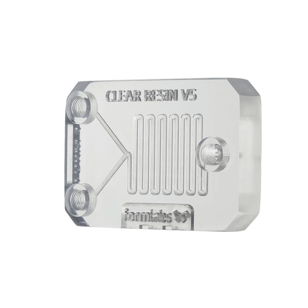
To perform our tests, we designed a model with four millifluidic channels, each of a decreasing diameter: 900 microns, 700 microns, 500 microns, and 300 microns. Best practices were determined by which methods resulted in smaller diameter channels resolving and allowing fluid flow.
Layer Height
Our test chips were printed at both 100 μm and 50 μm layer height, all in Clear Resin. The results are as follows: we recommend printing at a 50 μm layer height to resolve channels down to 700 μm wide in most orientations.
Resin Choice
Formlabs offers several options for optically clear resins. While Clear Resin (a General Purpose Resin) is great for prototyping, BioMed Clear Resin and High Temp Resin can also provide the required properties for common millifluidics applications:
- BioMed Clear Resin is an autoclavable biocompatible material that is hard, strong, and wear-resistant. BioMed Clear Resin can also print with a 50 μm layer height for super precise channel geometry.
- High Temp Resin can handle the high temperatures of cooling applications (like a thermoforming buck with integrated cooling channels), and can be printed with a 25 μm layer height for the smoothest channel profiles.
Post-Processing
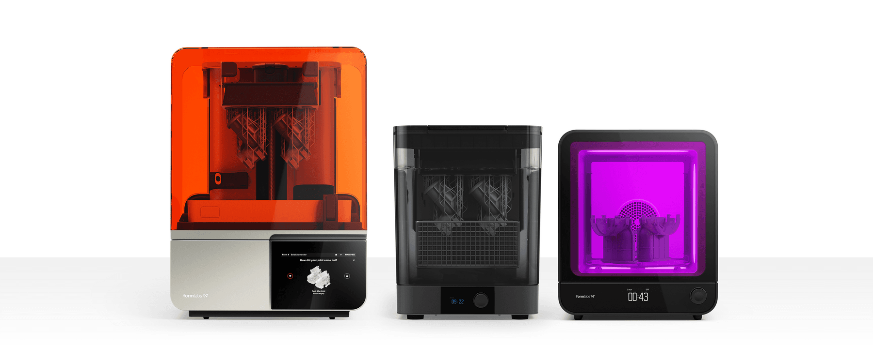
Form 4 with a Form Wash and Form Cure (2nd Generation).
We tested dozens of different post-processing techniques to find the optimal procedure for resolving tiny channels in millifluidic chips. These steps will set you up for success when printing narrow channels:
- Remove the Build Platform from the printer and immediately bring it to your Form Wash. Take a syringe filled with IPA and wash out the channels.
- Place the parts into a Form Wash with new or very clean IPA for a 10 minute wash cycle. Even minimal exposure to light at this stage poses a significant risk of sealing up the channels.
- Use a syringe filled with IPA to once again flush and thoroughly clean the channels. We had good results allowing at least 50 mL of fluid to flow through the channels less than 1 mm in diameter.
- Upon completion, immediately use a clean syringe to siphon out the remaining resin inside the channels.
- Remove the chip from the Build Platform and put it in a wash cycle again for 10 minutes.
- Push air through the cleaned channels with a syringe until the channel is visibly clear and has no fluid remaining inside.
Orientation
As with the majority of additive manufacturing processes, SLA can sometimes produce parts that warp very slightly after printing. But with a field as precise as millifluidics, dimensional accuracy is a crucial component for success. Orientation of your chip on the build platform plays a large roll in how your part cools and warps.
Testing shows that printing millifluidic chips vertically results in the least amount of warping. Users may need to print a few different versions of their chip to find which one creates the best channels for their geometry. Light touch supports mean minimal damage and residue to the chip surface when printing on an angle.
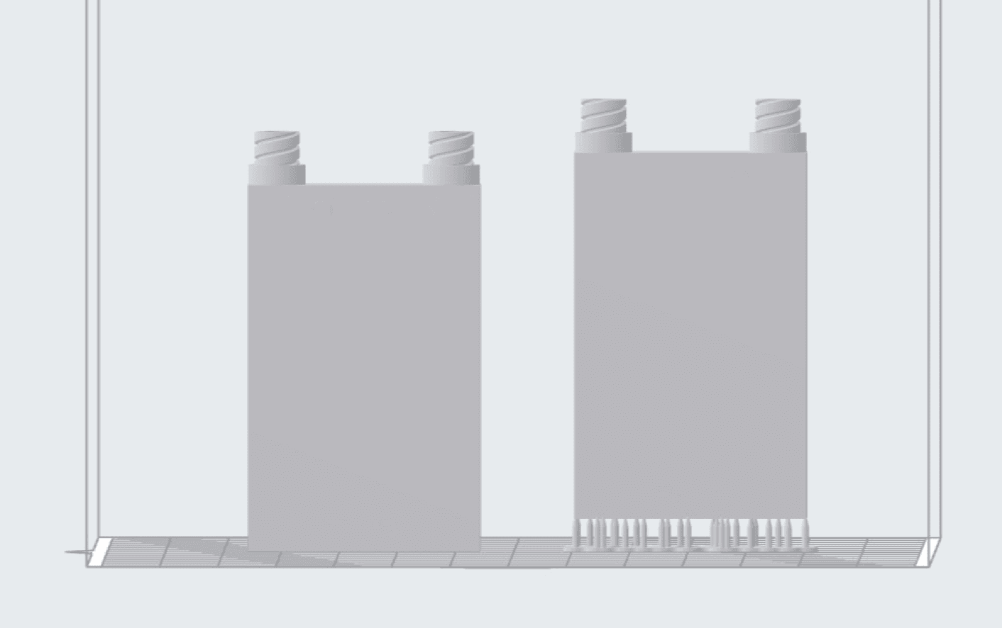
We saw print success with vertical prints, both directly on the build platform and on supports. Printing directly on a Build Platform Flex will make the part easier to remove.
Clear Coat
After chips are printed, achieving optical clarity is crucial for observing experiments and operating the chip in many applications.
Excellent surface finish is best done with a combination of sanding and coating. Start sanding the surface of your part with 220 grit sandpaper, and gradually work your way up to 1000. Putting your sandpaper on a flat surface and sanding your part against it is a great way to ensure the part stays flat.
After sanding, we recommend three coatings should you choose to go that route: Rustoleum 2X Glossy Clear coat, SprayMax Automotive Clear coat, and a layer of uncured resin. Clear coating may be necessary on older SLA printers, such as the Form 2.
All three coatings improved the optical clarity of the part to varying degrees, with resin coating providing the smoothest, and therefore clearest surface. However, there may be some distortion around the edges of the chip due to the meniscus.
Curing a resin coating also requires extra steps: the part must undergo a second cure cycle. Excessive post-curing can increase brittleness which may be detrimental to the strength of connectors and ports. Due to the optical clarity of Clear Resin prints on Form 4 and Form 3, it is often not necessary to coat the chip before use.
Conclusion
For a small startup or a research lab, the high cost for customized millifluidic chips is significant. 3D printing allows researchers to create custom geometries on demand, eliminating the bottleneck of outsourced chip manufacture. Form 4 is more than capable of handling a range of millifluidic chip geometries, printing each at a fraction of the cost.
With Form 4, desktop 3D printing has never been easier. Request a free sample part to evaluate the results for yourself or contact sales to learn more.