
You can 3D print parts larger than the build volume of your desktop 3D printer in a number of ways. Split parts into smaller sub-assemblies and fasten them using a bonding agent, or add screw threads and pockets for a robust mechanical connection for functional engineering parts.
For experienced—and experimental—CAD designers, integrating space-saving design elements like hinges, extending features, and moving parts into your 3D model can enable large parts to print in a single build, with no assembly required. These complex features, overhangs, and cavities can push utilization of a 3D printer's build volume to the maximum.
Design methods for creating space-saving design elements include:
- Foldable features: Hinges attach different parts of an assembly that can be unfolded after printing, similar to foldable tables or collapsing chairs.
- Extending or retractable features: Commonly found in headphones, umbrellas and other products to change the size during use or ensure a secure fit.
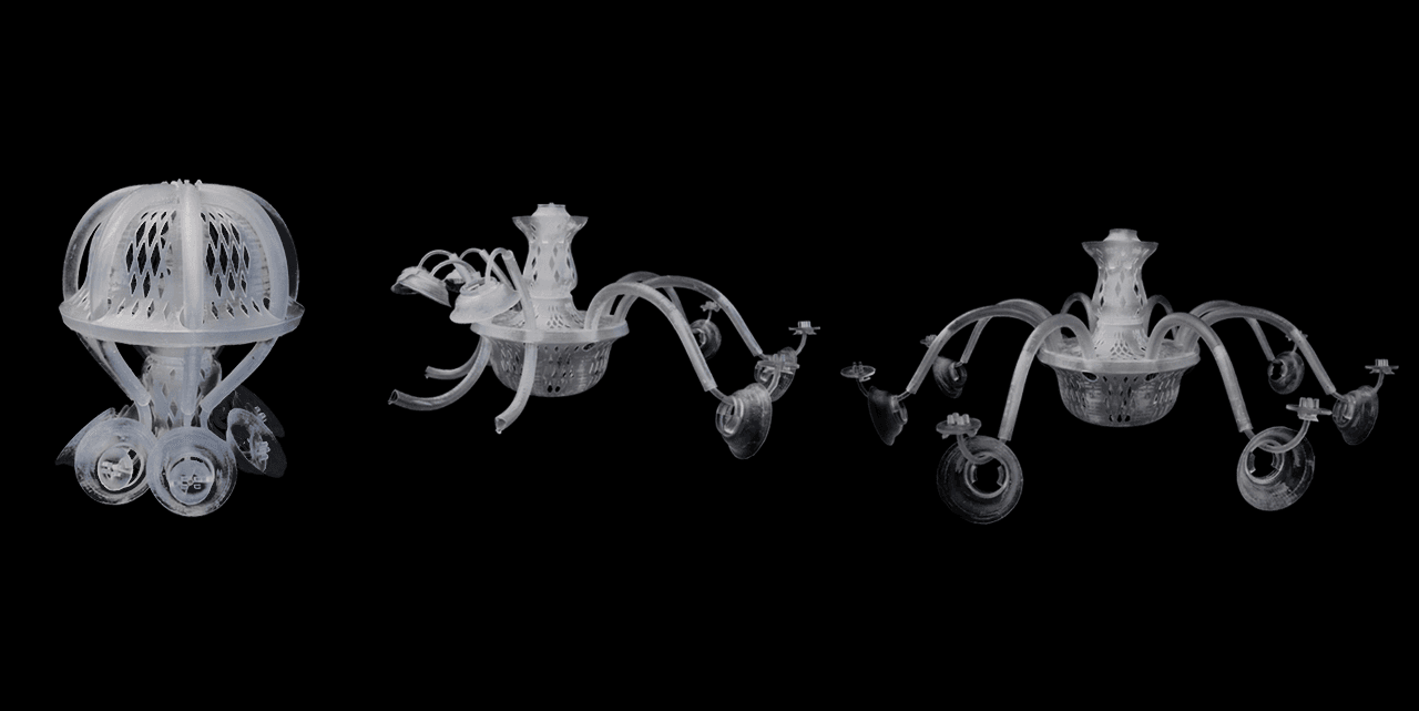
In this guide, designer and light artist team Studio Waldemeyer showcases two stunning chandelier designs that demonstrate design guidelines and optimizations for creating complex models. Explore foldable, retractable design elements that can be printed with stereolithography (SLA) 3D printing.
Note: This walkthrough is tailored to advanced CAD users with experience in 3D printing.
See how Studio Waldemeyer created their unique chandelier design.
Testing the Limits of SLA 3D Printing
Studio Waldemeyer developed the chandelier project to test pushing the Form 2 SLA 3D printer's build volume to its maximum.
During the design phase, the team had to consider the load-bearing capacity of the connection points, which depended on the parts’ intended functionality.
Studio Waldemeyer printed the chandeliers in Standard Black and Clear Resins and with an Engineering Resin, Rigid Resin. These materials offered sufficient rigidity and strength for thin features and could support the weight of the LED lights.
The designers did everything they could to minimize the support structures required to 3D print the design as well. This saved space during printing and reduced the post-processing required to remove the support structures after printing.
In the first, experimental phase, the designers sought an appropriate surface structure for the chandelier design—one that was both aesthetically pleasing and self-supporting during printing.

After experimenting with Voronoi patterns and hexagons, a diamond pattern prevailed as an aesthetic and functional solution for a form with the fewest possible support structures.

Formlabs’ PreForm print preparation software highlights areas that are not supported sufficiently in red. As long as no isolated areas, or so-called “islands,“ remained during printing and self-supporting structures had a wall thickness of at least 1 mm, the studio found that larger red areas could also be printed.
Learn more about optimal alignment and support of your model.


Design Guidelines
Hinges for Foldable Features

Uncured liquid resin in cavities can prevent hinges from moving after the part is post-cured. The designers found that a 0.5 mm clearance is required to thoroughly clean resin out of the joints.
Chandelier With 3D Printed Hinges
Studio Waldemeyer’s hinged chandelier design has eight arms that unfold with hinges, three extendable elements, and a main body. The entire model fits in the build volume of the Form 2 (145 x 145 x 175 mm) and unfolds to a full size of 447 x 447 x 447 mm.

Extending Features

Extending features must be designed with sufficient tolerance for cleaning and functionality.
The extending arm (marked with violet on the technical drawing above) shows the margins around the arms with varying tolerances between 0.7–1.4 mm. The gap for the extending arm (marked with 0.7 mm clearance) must be narrower than the widest diameter of the extending feature (marked with 0.8 mm clearance) to provide an interference fit that locks the parts together upon extension.
The internal cavity has a greater clearance of 1.4 mm to allow the arm to extend and the uncured resin to be easily washed away after printing.

Chandelier With 3D Printed Extending Arms
The chandelier with extending arms, Studio Waldemeyer’s largest design, features eight extending arms, three further extending elements, and the main body. The design unfolds to a full size of 529 x 529 x 374 mm.

Latching Mechanism

For the LED light holders, the shell (blue) and the holder (red) are printed separately to save space. After printing, they can be attached with a simple rotation. This design has less than 0.5 mm margins to provide an interference fit.
Results and Learnings

The team at Studio Waldemeyer had no prior experience with the desktop stereolithography or the Form 2 3D printer and spent about three months on the initial design, subsequent iterations, and completion of two variants on their bespoke design.
Both designs demonstrate how to expand desktop 3D printer’s build volume with some creativity and CAD expertise. The first design with hinges has a bounding volume 24 times larger than the build volume of the Form 2, while the second design with extending arms is an impressive 28 times larger.
We would like to thank Studio Moritz Waldemeyer (@moritzwaldewayer) for sharing their insights on their unique chandelier designs. Tweet at @formlabs or tag us in your posts on Instagram (@formlabs) to share your work.