
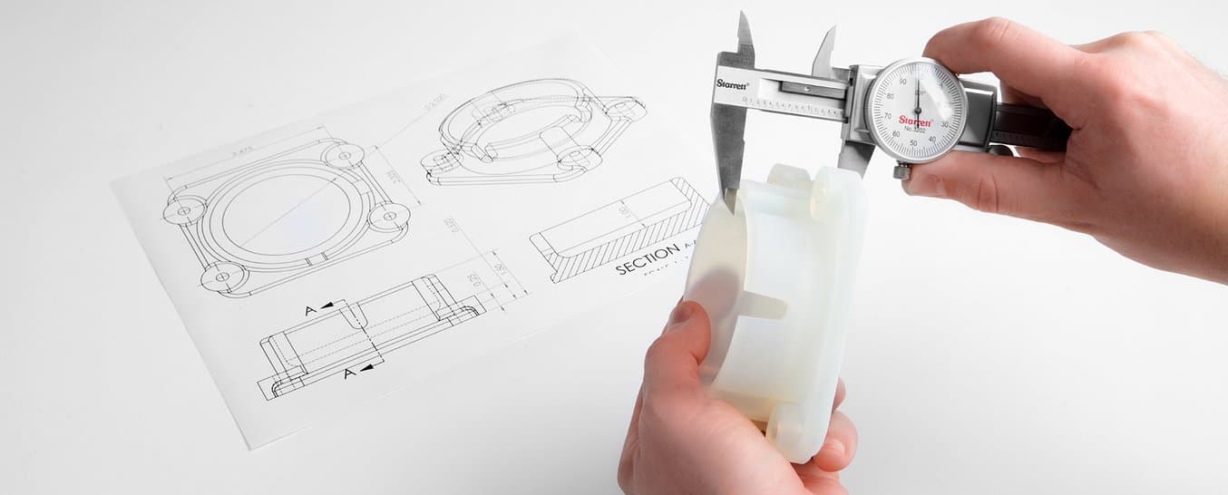
3Dプリンタの仕様に「高解像度」とあっても、造形品が正確かつ高精度になるとは限りません。
3Dプリントであらゆる用途で意味のある結果を出すためには、精度、精密さ、公差を正しく理解することが大切です。この記事では、これらの用語の意味を整理し、3Dプリントの文脈でどう捉えるべきかを説明します。そのうえで、各種3Dプリント方式で期待できる公差範囲を比較し、3Dプリント製アセンブリの公差設計について詳しく解説します。
具体的な造形結果については、FormlabsのFormシリーズSLA光造形プリンタおよびFuseシリーズSLSプリンタの精度調査の詳細をご覧ください。
精度、精密さ、公差の定義
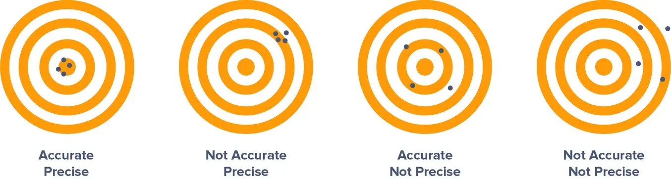
まずは言葉の定義から始めましょう。精度、精密さ、そして公差の違いは何でしょうか?各用語について、理解しやすいよう射撃を例にしながら視覚的に説明します。
精度
精度とは、測定値が真の値(理想値)にどれだけ近いかを示す指標です。射撃に例えると真の値は的の中心(ブルズアイ)のことです。中心に近ければ近いほど、射撃の精度が高いということになります。3Dプリントの世界では、真の値はCADで設計した寸法です。実際に3Dプリントした造形品が、デジタル設計とどの程度一致しているかがポイントになります。
精密さ
精度は、測定の再現性、つまりどれだけ一貫して同じ結果を得られるかを示す指標です。射撃の例では、毎回同じ場所に命中するかどうかを見るのが精密さです。毎回同じ場所に当たることが大切であり、それが必ずしも的の中心である必要はありません。3Dプリントの文脈では、最終的に信頼性につながる重要な要素で、プリンタが毎回期待通りの結果を出してくれるかどうかを左右します。
公差
では、どの程度精密であれば良いのでしょうか?それはユーザーが定義する公差によって決まります。想定の用途によって、どの程度の誤差が許容されるかが変わります。精密さの測定値に対してどの程度のばらつきなら許容範囲に収まるのかはプロジェクトによって異なり、例えば動的な機械的アセンブリを含む部品とシンプルなプラスチック製のエンクロージャとでは、前者の方がより厳しい公差が求められます。
公差を定義する場合には精度も重要視されるはずですので、ここでは的の中心を狙った場合の射撃の精密さを測定すると仮定します。先ほど、右側の図の射撃は「精密ではない」と定義しました。

しかし、公差範囲、つまり許容されるばらつきの範囲が広い場合には、右の図でも問題にならないことがあります。左の図ほど弾の位置が的の中心に集まっていないとしても、仕様として精密さの許容範囲が±2.5リング以内であれば「仕様内に収まっている」と言えます。
一般的に、より厳しい公差を達成・維持するには、製造コスト・品質保証の基準ともに高くなります。
無料相談セッションのご予約
3Dプリントのエキスパートに一対一でご相談いただける相談セッションをご用意しています。ROI 分析やテスト・プリントなどを通して、お客様のビジネスに最適なソリューションを一緒に考えましょう。
3Dプリントの公差、精度、精密さに影響を与える要因
3Dプリントにおける精度と精密さを考える際は、様々な要因を考慮する必要があります。プリンタが商品説明通り一貫した動作を続け、ユーザーが求める公差内で期待される品質を達成できるとわかっていること。これが、成功体験を得るために極めて重要になります。
3Dプリントの精度と精密さを決める4つの大きな要因は、以下のとおりです。
造形方式
3Dプリントは積層造形プロセスであり、パーツは一層ごとに形成されます。そのため層ごとに誤差が生じる可能性があり、層を形成するプロセスは各層の精度や再現性(精密さ)に影響を与えます。一般的なプラスチックを使った3Dプリント方式の場合、典型的な公差は以下の通りです。
- SLA光造形およびDLP(デジタルライトプロセッシング):フィーチャーの大きさが1〜30mmで±0.15%、31〜80mmで±0.2%、81〜150mmで±0.3%。下限は±0.02mm。
- 光造形では、液体レジンに光源を選択的に照射し、非常に薄いプラスチックの固体層を形成して積み重ね、ソリッドオブジェクトを作ります。高密度な光源のおかげで細部まで丁寧な表現が可能で、一貫して高品質な結果を得ることができます。複雑な形状や大型モデル、または薄肉構造など、モデルの形状によっては寸法精度を確保するためにサポート材が必要になる場合があります。
- SLS(粉末焼結積層造形)およびMJF(マルチジェットフュージョン):±0.5%または0.3mmのいずれか大きい方
- 粉末焼結方式の3Dプリンタも光源の精度(SLSではレーザー、MJFではヒューズ型ランプ)に依存しており、粉末材料を融合させてソリッドパーツを作ります。造形中は未焼結パウダーが造形品を支えるため、専用のサポート材が必要ありません。内部構造やアンダーカット、薄壁や凹面等、複雑な形状の造形に最適です。
- FDM(熱溶解積層):±0.5%(下限:±0.5 mm)
- FDM 3Dプリントでは、熱可塑性フィラメントをノズルから押し出して層を形成します。他の3Dプリント方式に比べ、細かいディテールを実現する制御力や能力に欠けます。造形品が異なる速度で冷却されることで反りや収縮が生じやすく、内部応力によって変形が生じやすい傾向にあります。高価格帯の工業用プリンタではこれらの問題が軽減されていますが、その分機器のコストも高くなります。
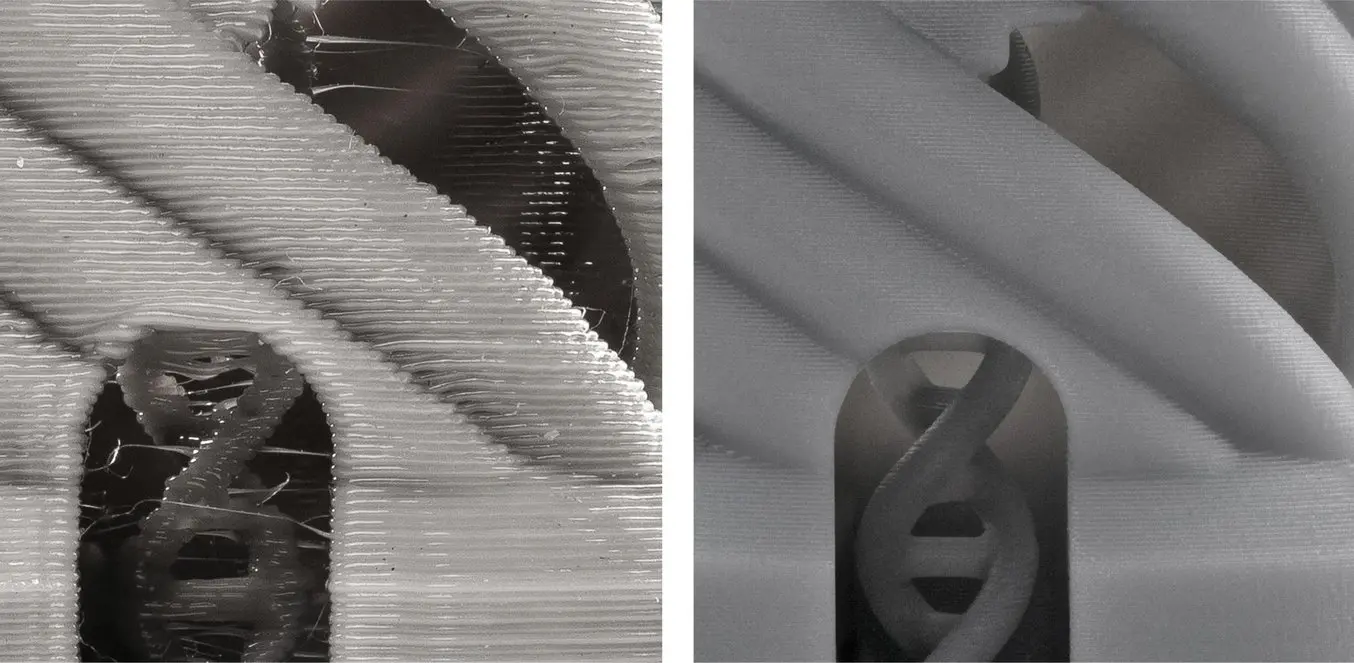
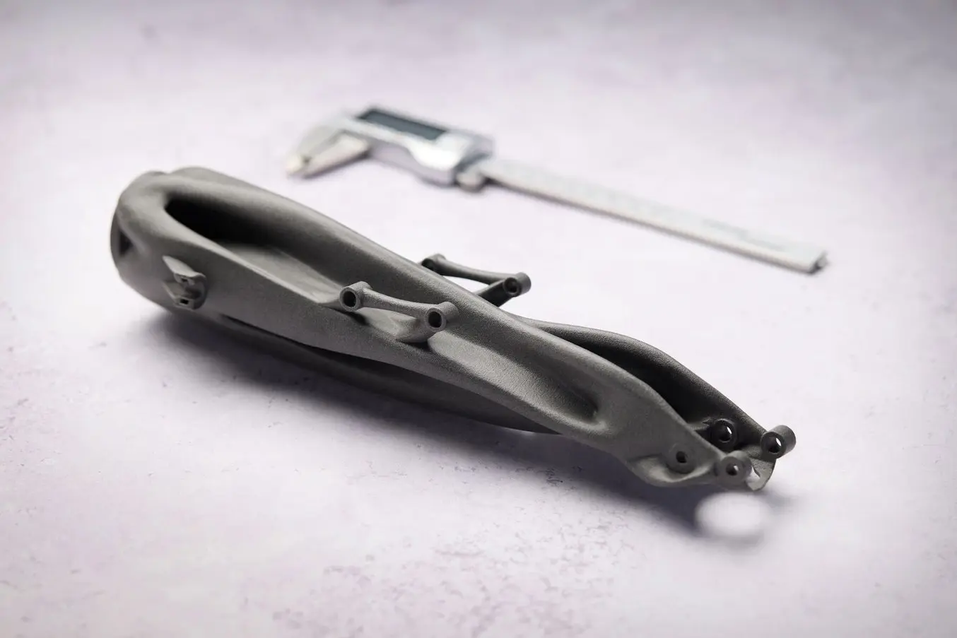
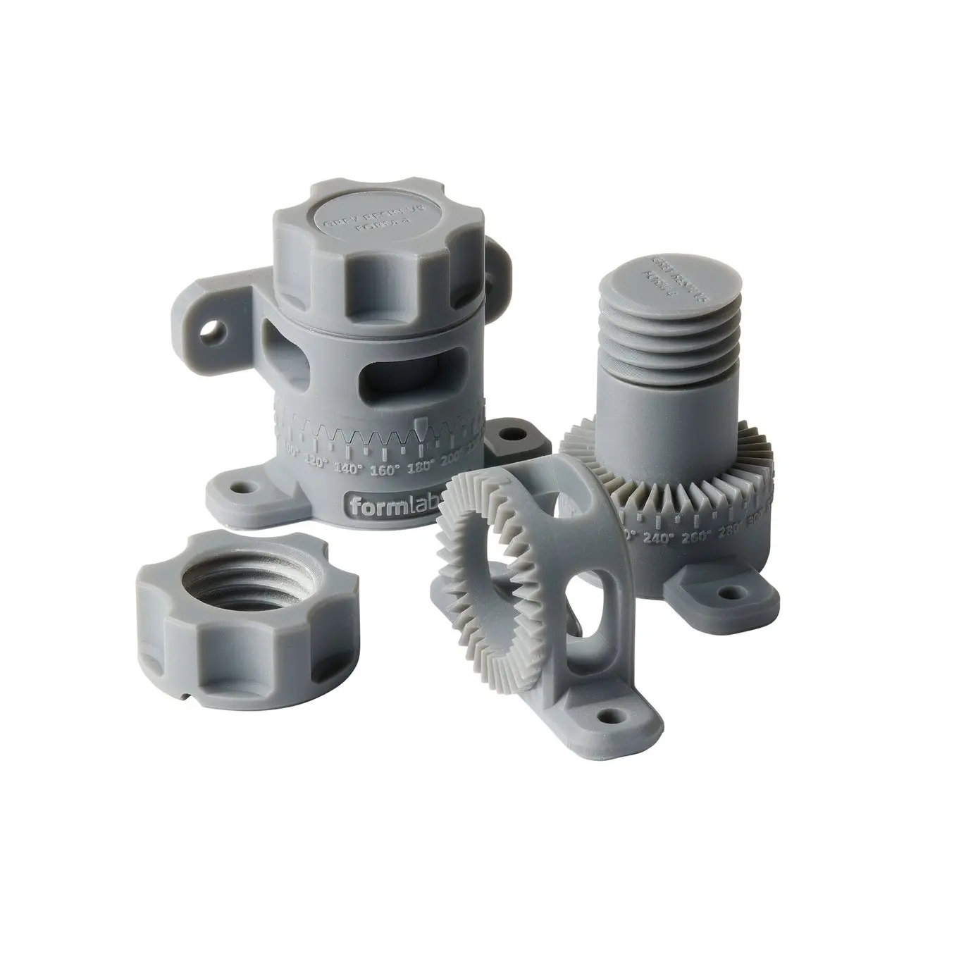
FDMではフィラメントを押し出してレイヤーを形成するため、複雑な形状では正確さが低下する可能性がある(左がFDMで造形したパーツ、右がSLA光造形で造形したパーツ)。
3Dプリンタの仕様だけでは、最終的な寸法精度を正しく表現することはできません。様々な3Dプリント方式でXY解像度やZ解像度(積層ピッチ)が寸法精度として表記されていますが、これはよくある誤解です。
これらのデータは造形品がどれほど正確になるかを示すものではありません。これ以外にも造形品の精度に誤差を発生させる要因は様々ありますが、以降のセクションで説明していきます。
結局のところ、実際の造形品を確認することが最も正しく3Dプリンタを評価できる方法と言えるでしょう。

材料
精度は、使用する材料によっても変わります。また、その材料の機械的特性が造形品の反りやすさにも影響します。
SLA光造形用のFormlabsRigid 10Kレジンは、グリーンモジュラス(二次硬化前の剛性)が高く、薄く複雑なフィーチャーを持つモデルのプリントが可能。
SLS用のNylonパウダーは、サポート材が不要で優れた機械的特性を持つため、公差要件の厳しい複雑形状のプリントに最適。
光造形3Dプリンタでは、材料のグリーンモジュラスが高い場合、非常に薄い構造のモデルを精密に造形でき、造形失敗の可能性も低くなります。
FDM方式の場合、高温で押し出される材料は他の材料よりも反りやすい傾向があります。例えば、ABSは冷却時により収縮するため、PLAよりも反りやすいことが知られています。
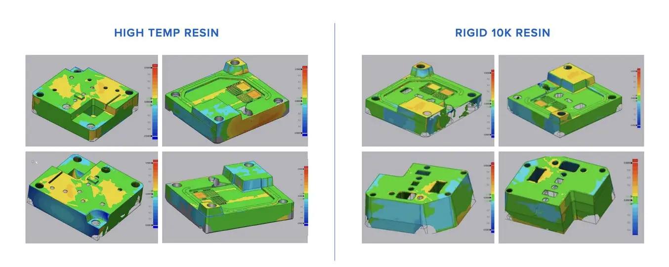
3Dプリント製の成形型を使った射出成形に対する技術研究を行うために取得した、3Dプリント製成形型のスキャン。75%以上の造形品で寸法誤差が±0.05mm以内に収まっている。
後処理
ほとんどの造形品は、プリント後に何らかの後処理が必要です。
- SLA光造形およびDLP:洗浄、二次硬化(オプション)、サポート材の除去(必要な場合)、サンディング(オプション)
- SLSおよびMJF:余分な粉末の除去、ブラスト処理またはバレル研磨
- FDM:サポート材の除去(必要な場合)、サンディング(オプション)
これら後処理工程の中には造形品の寸法や表面に影響を与えるものもあり、結果として精度や公差の変動にもつながります。設計時や造形準備中に考慮・対策が可能なものもありますが、造形品ごとに変動する場合もあります。
例えば、光造形3Dプリントでは造形後に二次硬化が必要なことが多く、この二次硬化によって収縮が生じます。これはレジンベースのSLA光造形またはDLP方式でプリントした造形品では普通のことで、プリンタによっては設計時に考慮が必要な場合があります。Formlabsの無償造形準備ソフトウェアPreFormでは、この収縮を自動的に補正し、二次硬化後の造形品が元のCAD設計と寸法的に一致するようにしています。
一方、FDM方式の造形品は、サポート痕や積層痕を除去して表面品質を向上させるためにサンディングが必要な場合がありますが、このプロセスは部品の寸法をわずかに変化させ、設計と完成品の間のばらつきを増加させます。
エコシステムとキャリブレーション
正確で精密な3Dプリントを行うには、プリンタ本体だけでなく、プロセス全体を考える必要があります。
造形準備ソフトウェア、プリント方式、プリンタとその構成部品の品質とキャリブレーション、3Dプリント材料の品質、後処理のツールや方法など、すべてが最終結果に影響を与えます。
一般的に、統合型のシステムはより信頼性の高い結果を生み出します。例えば、Formlabsの新しいSLA光造形およびSLS用3Dプリント材料は、リリース前に対応する各プリンタで一連の検証テストを行い、信頼性、一貫性、正確さを確実に実現できるようにしています。必ずしも汎用プリンタや市販の材料が良い結果を出せないということではありませんが、導入後にユーザーによる試行錯誤やキャリブレーションが必要となる可能性があります。
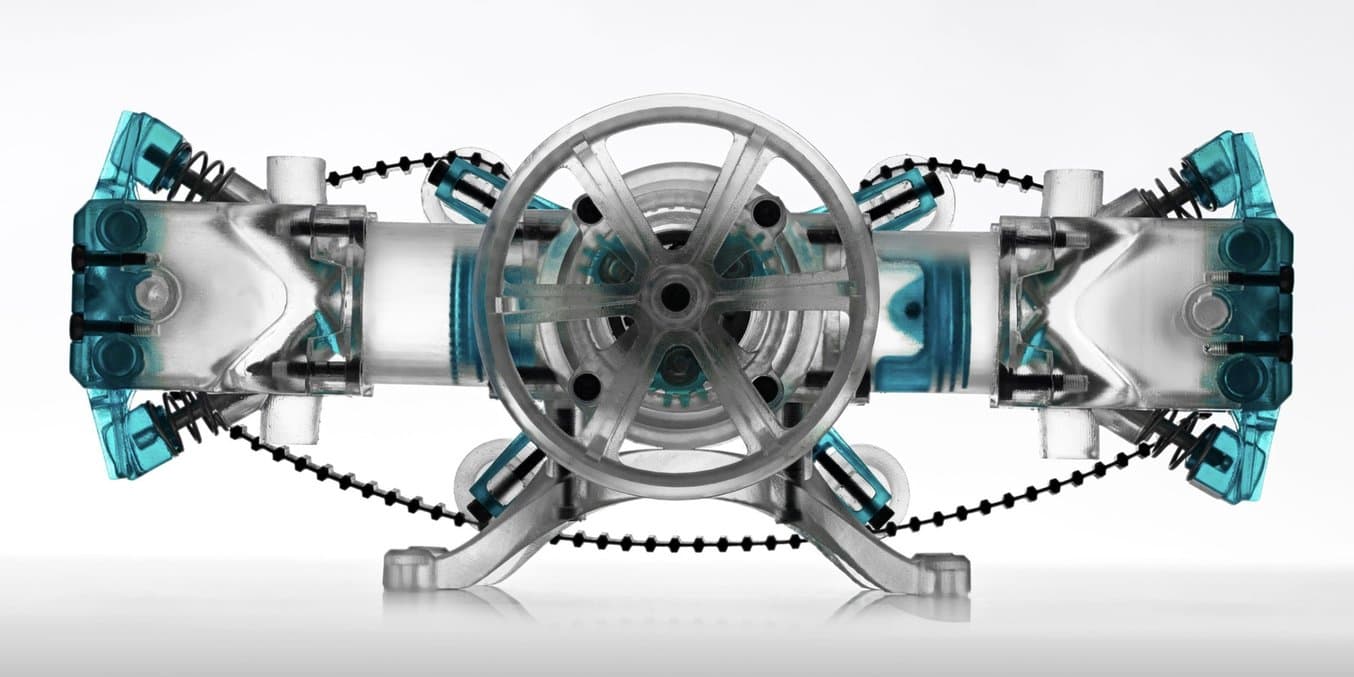
Formlabsレジンを使ってプリントし、鉱物油で潤滑された空気駆動の水平対向2気筒内燃機関エンジンの機能的なスケールモデル。
3Dプリントにおける公差の設定
従来の機械加工では、より厳しい公差を達成するにはコストが大幅に増加してしまいます。厳しい公差は追加の加工ステップや時間を要するため、機械加工部品は可能な限り公差を広く取って設計される傾向があります。
一方、3Dプリントでは自動化された単一の生産ステップで製造が完了します。公差を厳しく設定すると、設計段階ではより多くの労力が必要になりますが、試作品製作や実際の製造時には時間とコストを大幅に削減できます。
また、CNC加工のように複雑な形状がコスト増につながるのに対し、3Dプリントでは複雑さは基本的に自由に設定できます。ただし、3Dプリンタの性能を超えて造形品の公差を精密化することはできません。3Dプリントは、アンダーカットや複雑な表面などの高度な複雑性が必要で、±0.005インチ(標準的な機械加工)以上の表面精度は不要な場合に最適な選択肢となります。標準的な機械加工の公差を超える場合は、3Dプリント部品でもCNC部品でも、手作業や機械加工による削り出しが必要です。
全体的に、光造形方式(SLA光造形およびDLP)と粉末床溶融結方式(SLSおよびMJF)は、市販のプラスチックを使った3Dプリント方式の中で最も公差要件への対応性が高い方式です。レジンおよびパウダーを使った3Dプリントの公差は、標準的な機械加工と精密加工の中間に位置すると言えます。
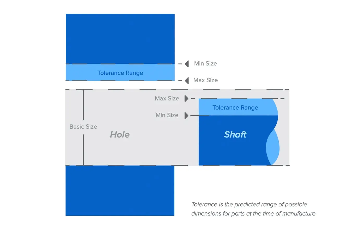
公差とは、製造時に予測される部品寸法の許容範囲のこと。
Form 4シリーズデザインガイド
3Dプリントの成功の秘訣は、モデルを適切に設計することにあります。以下にベストプラクティスをご紹介します。設計の最適化やプリント失敗を最小限に抑えるヒントとしてお役立てください。
Fuseシリーズデザインガイド
本デザインガイドでは、Fuseシリーズを使ってSLS方式の3Dプリントをする際に考慮すべき重要なポイントをご紹介するとともに、このポイントを実際に活用してプリントを成功させる方法を解説しています。
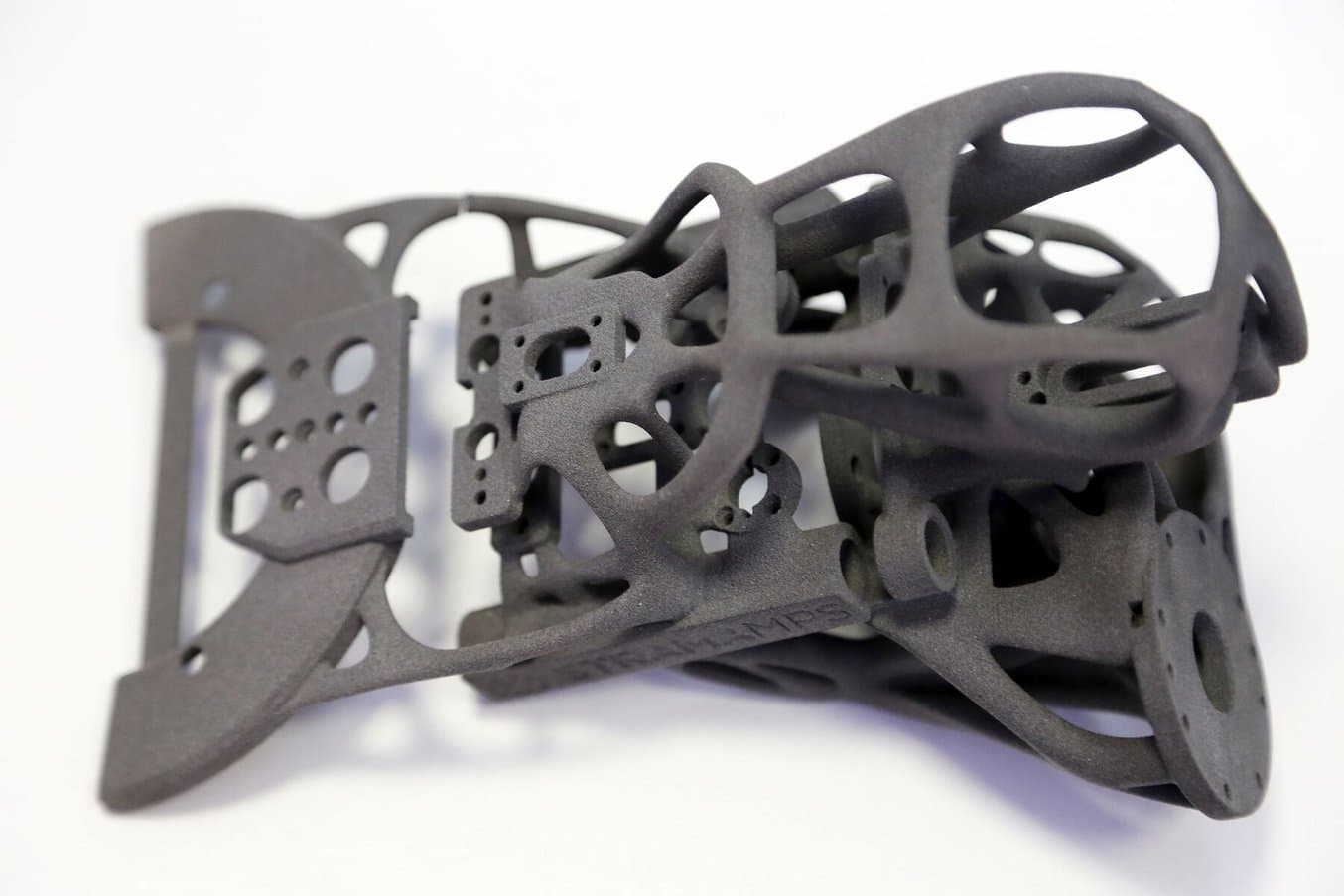
3Dプリント製の大型アセンブリや小型部品のための公差設定
機械的アセンブリを設計するエンジニアにとって、公差とはめ合いは重要な概念です。公差を考慮した設計により、プロトタイピングと生産プロセスの両方を最適化し、試作・検証プロセスにかかる材料費の削減、後処理時間の短縮、部品の破損リスクの低減が可能になります。3Dプリントは、特にカスタム部品のプロトタイピングや小ロット生産においてコスト効率の高い方法です。
一般的に、より柔軟性の高い3Dプリント用材料は、より硬質な材料よりも公差が広くなります。特にアセンブリ用の部品をプリントする場合、公差とはめ合いを適切に設計することで、後処理時間の短縮や組み立ての簡素化、試作・検証プロセスにかかる材料費の削減が実現できます。
3Dプリント製アセンブリの後処理には、洗浄、サポート材の除去・サンディング、潤滑などが含まれます。一点ものの場合、後処理でアクティブサーフェスをサンディングして適切なはめ合いを実現するのが設計段階での公差設定作業が少なく済む合理的な方法です。しかし、大型アセンブリや複数の部品を製作する場合には、設計時に適切な寸法公差を設定することが重要になります。
このセクションではエンジニアリングで使われるはめ合いの種類を順に見ていき、クリアランスフィット、トランジションフィット、インターフェアランスフィットの基本と、アセンブリ設計でどのような場合にそれぞれを選択すべきかを説明します。
エンジニアリングで最適なはめ合いを選ぶ
最適な3Dプリントの公差を理解し設計に反映させるには、アセンブリに最も適したはめ合い種別を見極めることが重要です
アセンブリに求める機能性が、部品同士のはめ合い方法を定義します。
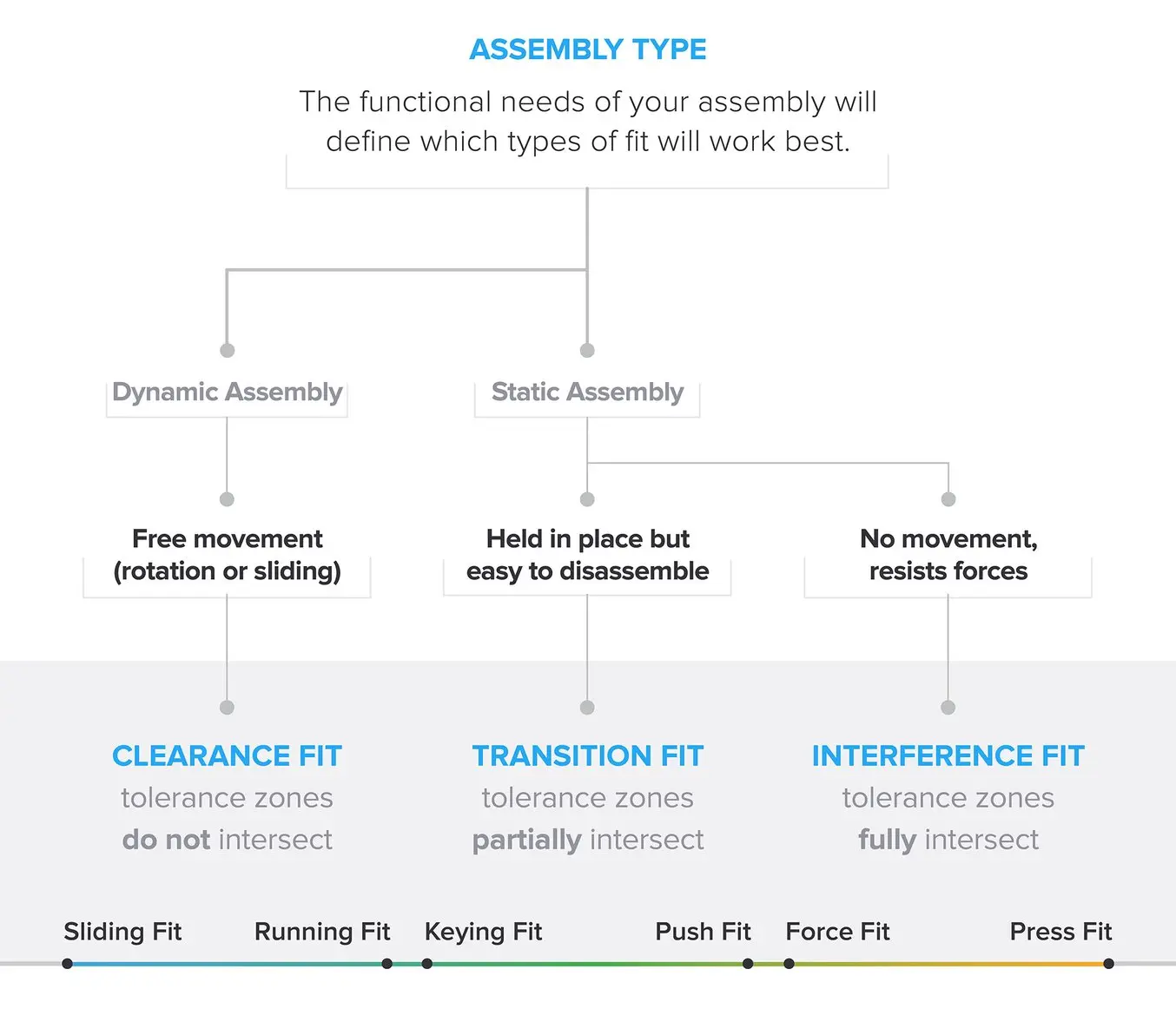
エンジニアリングにおけるはめ合いの種類は、クリアランスフィット、トランジションフィット、インターフェアランスフィットの3つのタイプに分けられ、その中でさらに2つの主要なサブカテゴリーに分類できる。
製造方法の違いや使用する3Dプリント方式によって公差にばらつきがあるため、はめ合いはそれぞれが完全に分離された段階ではなく、連続的なものとして考えるのが良いでしょう。例えば、クリアランスフィットがより大きい場合には精度と動きの自由度がトレードオフになります。トランジションフィットがより狭い場合は強度が増しますが、接続部の摩耗しやすくなります。より大きな力を必要とするインターフェアランスフィットは、分解が難しくなります。
クリアランスフィット
部品が自由に動けるようにするためには、アクティブサーフェスにクリアランス(空間)が必要です。アクティブサーフェスの公差ゾーンが重ならないようにすることで、クリアランスを実現できます。
アクティブサーフェスとは、2つの表面が接触し、互いに動いたり静的にはめ合ったりするモデル上の領域のことです。
サブカテゴリー:
- すべりばめ(スライディングフィット)は横方向にある程度遊びがありますが、すきまばめ(ランニングフィット)はほとんど遊びがありません。
- すきまばめ(ランニングフィット):わずかに摩擦が増えますが、動きをより正確に制御できます。
遊びとは、機構内で意図しない方向への動きを許すための空間のことです。
トランジションフィット
部品間の動きが必要ない場合、トランジションフィットにより組み立てや分解が容易になります。トランジションフィットは、公差ゾーンが部分的に重なります。
サブカテゴリー:
- キーイングフィット:部品が他の部品の中や周りに正確に挿入され、軽い力で取り付け・取り外しができます。
- プッシュフィット:部品の結合・取り外しにより多くの力が必要ですが、手で接続できます。
インターフェアランスフィット
インターフェアランスフィット:剛性の高い強力な結合が可能ですが、組み立て時により多くの力を必要とします。インターフェアランスフィットでは、公差ゾーンが完全に重なります。
サブカテゴリー:
- フォースフィット:ハンマーなどの工具を使ってかなりの力で取り付ける必要があり、永久的な結合を目的としています。
- プレスフィット:ハンドプレスなどの工具を使用して、より多くの力をかけて取り付ける必要があります。
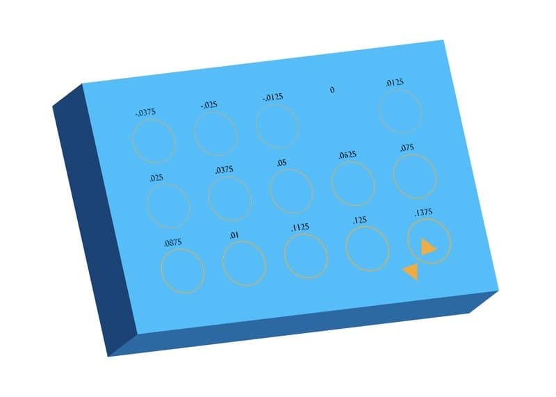
公差の測定と適用
はめあいの種類に応じて求められる実際の公差を把握するには、以下のような代表的な形状を評価するとよいでしょう。
穴とシャフト
必要な精度に応じ、通常はすべりばめからランニングフィットまでのクリアランス条件が想定されます。すべりばめでは、自由な動きを出すために十分な潤滑が必要です。
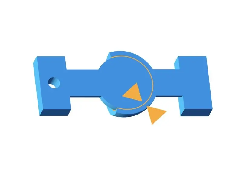
ボールとソケット
ボールがソケット内で自由に回転できるよう、クリアランスが必要です。ただし、ボールの半径とソケット開口部の間には大きな干渉が生じます。開口部は、ボールを押し込める程度には変形可能でありながら、通常使用ではボールが中から出てこないようにする必要があります。
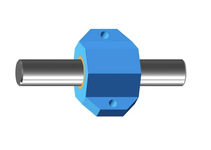
ロッドとブッシュ
ブッシュはプレーンベアリングの一種で、ロッドに沿って滑らかかつ自由な動きを可能にする設計になっています。ロッドとブッシュの間にはすきまばめが必要で、用途によって必要なクリアランスの大小が変化します。
摩擦
2部品間の摩擦の大きさは、はめ合いの接触表面にかかる荷重(フィット感に直接関連)と、材料固有の定数(摩擦係数)の積で決まります。摩擦係数は、部品の動きや摩耗に連動してどの程度の摩擦が発生するかを予想したり、Formlabsレジンが他の一般的な材料と比較して相対的にどの程度の性能を発揮できるのかを把握するのに有用です。

Formlabsでは、重量そり・トラック・荷重計を用いて摩擦係数を測定します。
Tough 1000レジンのように潤滑性の高い材料は、摺動摩擦が低くなります。摩擦係数が低い材料は、運動アセンブリで相互に作用する可動部品に適しています。
レール、ピストン、ロッドなどの摺動部では、2つのはめ合い面の接触面積を減らすことで摩擦力が低下します。これは、レイヤーの「木目」(積層パターン)が部品間で垂直になるようようにPreFormでモデルの向きを調整することで実現できます。積層方向を平行にすると、レイヤーの溝が噛み合い、表面積が増えて静摩擦・動摩擦が大きくなります。
表面の方向と摩擦力の関係を示す簡略図

左:静摩擦・動摩擦とも最大。中央:静摩擦が大きく動摩擦は中程度。右:静摩擦・動摩擦とも最小。
静的・動的いずれの試験でも、垂直向きの方が摩擦係数が低くなりました。静摩擦係数は、積層方向の影響をより強く受けます。表面の摩耗が進むにつれ、部品間の摩擦は低下します。これは運動アセンブリに有利に働くことが多く、サンディングや研磨は意図的に摩耗させる手法の一例です。ただし、過度の摩耗は部品間のクリアランスを増大させる原因になります。長期的な摩耗を抑えるには、潤滑が最善の方法です。
ローラーやホイール、ロボットグリッパなど、ものによっては摩擦が大きい方が有利な用途もあります。その場合は、摩擦係数が高く潤滑性の低い材料を選定してください。
潤滑
運動アセンブリで部品をスムーズに動かすには、潤滑剤が不可欠です。SLA光造形品には、安価で入手しやすい潤滑剤として鉱油がよく使用されます。Super Lube® などのシリコンオイル系潤滑剤も有効で、べたつきにくく長持ちします。
接着部品
造形部品を接着剤で接合する場合は、クリアランスが狭いことが理想です。シアノアクリレート系(瞬間接着剤)は低粘度のため、薄い隙間も埋めることができます。UVまたは青紫色(波長405nm)のレーザーペンでレジンを局所硬化させ(使用時にはUV用の保護ゴーグルを着用してください)、部品同士を「溶接」させて突合せ接合することも可能です。
造形品の加工
3Dプリント製のアセンブリの仕上げ処置には、サンディング・研磨・潤滑が最も一般的です。必要公差が0.025mm未満にする必要があるなど厳しい要件が求められる場合や、造形後に形状を変更したい場合などは、プラスチック部品を後から加工することがあります。
プリント中に設計変更が必要になり、必要なツールをすぐに使用できる場合には、ドリルで穴あけしたり、タップでねじ山を切る方が、プリントをし直すより迅速で効率的な場合があります。Tough 1000レジン、Tough 1500レジン、Tough 2000レジンを含むToughレジンファミリーは、強度と伸び率が高く、Formlabs材料の中でも群を抜いて加工への耐性があります。その他のFormlabsレジンも加工自体は可能ですが、より保守的な加工方法や高速なツールが必要になります。
用途に最適な3Dプリント用材料を探す
製品設計の実務においては、材料特性と機能要件に基づいてはめ合いを定義することが不可欠です。上記で示した代表的な形状の適合範囲は、多くの設計に幅広く適用でき、試作・検証の回数を抑えながら機能確認用試作を作ることができます。精度をさらに高め、部品の組み付き具合を直感的に把握するには、幅広い材料でテストモデルを造形し、各部品の挙動を確認します。
こちらでご紹介したポイント以外にも、3Dプリンタを評価する際に考慮すべき点は多数あります。部品は等方的である必要があるか、どのような機械的特性が求められるのか、など、機能的な部品製作には用途と要件に合った材料選定が欠かせません。Formlabsの材料は、それぞれ引張強さ・伸び率・耐摩耗性が大きく異なります。
お客様用途に最適な材料の確認には、Formlabsの材料比較ページを参照いただくか、各材料の品質確認には無償サンプルパーツをお申し込みください。