WHITE PAPER
Formlabs Logo

Build platform flashing or elephant’s foot

Build platform flashing or elephant’s foot

Build platform flashing, also known as an elephant's foot, refers to a print defect in which extra cured material splays out from a part where it contacts the build platform. This extra material helps promote adhesion to the build platform, particularly for large parts whose shrinkage can cause them to pull away from the build platform. Formlabs settings are generally tuned to minimize excess flashing while keeping the adhesion high enough to print any model you choose. If your parts do not need extra adhesion or you want to reduce post-processing, you can use the Print Settings Editor to reduce build platform flashing.

Visual symptoms

  • Base of part is wider than intended
  • Extra cured material around the base of a part
  • Parts are overadhered to the build platform and become difficult to remove
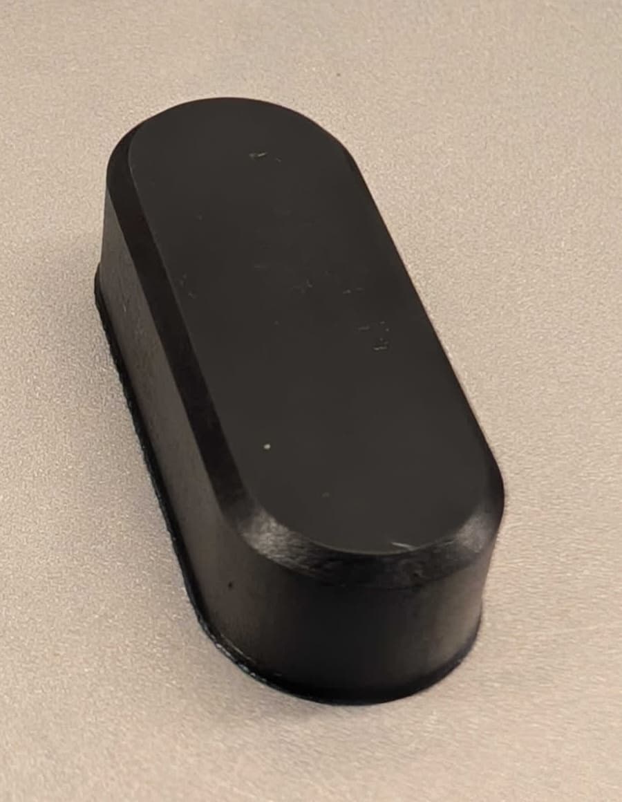
Example of build platform flashing on a part printed in ESD Resin

Common causes

  • Early layer parameters improperly tuned for your models or print workflow
  • Overcompression

Troubleshooting steps

Note:

Make sure that your firmware and PreForm versions are up to date. To check your printer's firmware version, refer to the support article Checking the firmware version for Formlabs SLA printers. To update your PreForm version, refer to the FAQ article How do I update PreForm?.

Check for and correct overcompression

If your parts are shorter than intended, the build platform flashing may be the result of overcompression. Fine tune your printer's Z-axis to correct any overcompression.

Adjust early layer parameters with the PreForm Print Settings Editor

To reduce build platform flashing, Formlabs recommends creating a custom print setting with the Print Settings Editor.

There is one main parameter that influences the amount of extra material that cures on the build platform: Early Layer Exposure and Offset.

Large offsets may cause undesirable artifacts, such as unexpected shrinking around irregular geometries. Small parts may also fail to print entirely; for example, a part that is 2 mm in width with an offset of over 1 mm would be deleted by the offset, causing any subsequent layers to fail to adhere to the build platform.

To avoid this, you can also reduce build platform flashing by reducing exposure. This approach can result in a somewhat robust connection to the build platform that won't over-erode parts, but larger parts that may warp or fall off of the build platform.


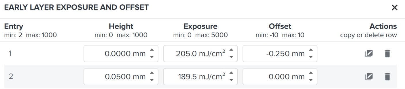
Early Layer Exposure and Offset entry in the Print Settings Editor

This parameter is a full array field, with three main fields:

  1. Height: the distance from the build platform that the listed exposure and offset will be applied
  2. Exposure: the exposure at the given height. Note that exposure = irradiance x time, if you are more familiar with time-based parameters in other slicing software.
  3. Offset: the amount that the layer exposed by the Light Processing Unit and Backlight Unit is enlarged or reduced to account for the extra material cured beyond the target dimensions
Editing Early Layer Exposure and Offset in the Print Settings Editor

If entries are set more than a single layer apart, PreForm interpolates linearly between the entries to ensure a smooth transition. For example, if the initial height is 0.00 mm with an exposure of 200 mJ/cm2 and the second entry has a height of 0.20 mm with an exposure of 100 mJ/cm2, the following layers will be exposed for a print with 50 micron layers:

  1. 0.00 mm: 200 mJ/cm2
  2. 0.05 mm: 175 mJ/cm2
  3. 0.10 mm: 150 mJ/cm2
  4. 0.15 mm: 125 mJ/cm2
  5. 0.20 mm: 100 mJ/cm2

Both Exposure and Offset can reduce overcuring and therefore build platform flashing. Formlabs recommends modifying the Offset values, as they can generally be calculated directly from a single test print. Additionally, Exposure is more crucial to ensuring good adhesion to the build platform, so lowering it too far can result in parts peeling off of the build platform or failing to adhere at all.

To reduce build platform flashing by adjusting the early layer offset:

  1. Measure the width of the flashing around the base of the part.
  2. Measure the width of the part above the flashing.
  3. Subtract the part width from the flashing width.
  4. Add half the value from step 3 to any preexisting offset in the first entry in the Early Layer Exposure and Offset array field.

For more information, see the example below.

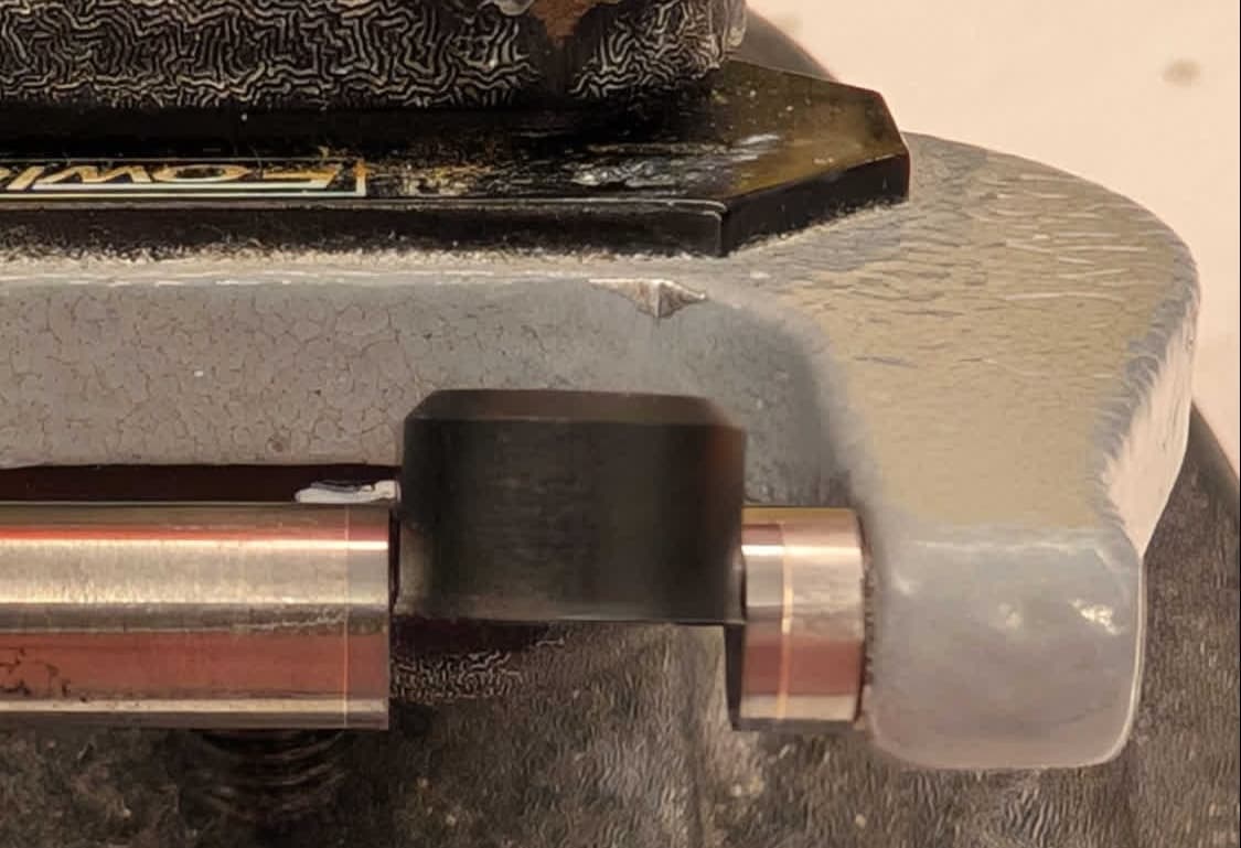
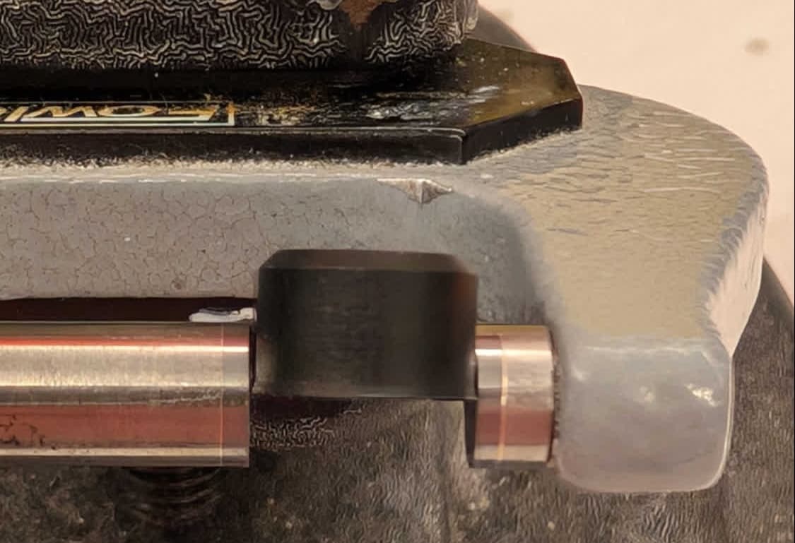
Measuring build platform flashing on a printed part

Tip:

For best results, Formlabs recommends using a precise and accurate measurement tool, such as a micrometer or calipers.

Form 3 and Form 3L generation


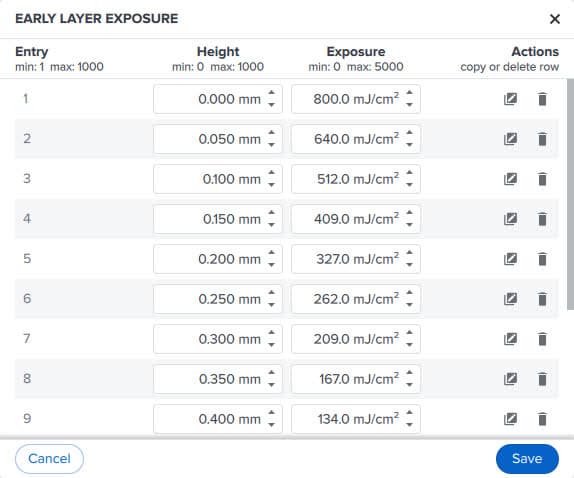
On Form 3 and Form 3L generation printers, you can adjust the Early Layer Exposure array to reduce build platform flashing. The required change cannot be measured directly from a finished print, so reduce the Exposure value listed in the first entry by small steps, running a small test print in between each change. Reducing early layer exposure too far will affect the overall adhesion of your printed parts to the build platform.

Editing Early Layer Exposure in the Print Settings Editor

Caveats, risks, and further adjustments

Large offsets may cause undesirable artifacts, such as unexpected shrinking around irregular geometries. Small parts may also fail to print entirely; for example, a part that is 2 mm in width with an offset of over 1 mm would be deleted by the offset, causing any subsequent layers to fail to adhere to the build platform.

To avoid this, you can also reduce build platform flashing by reducing exposure. This approach can result in a somewhat robust connection to the build platform that won't over-erode parts, but larger parts that may warp or fall off of the build platform.
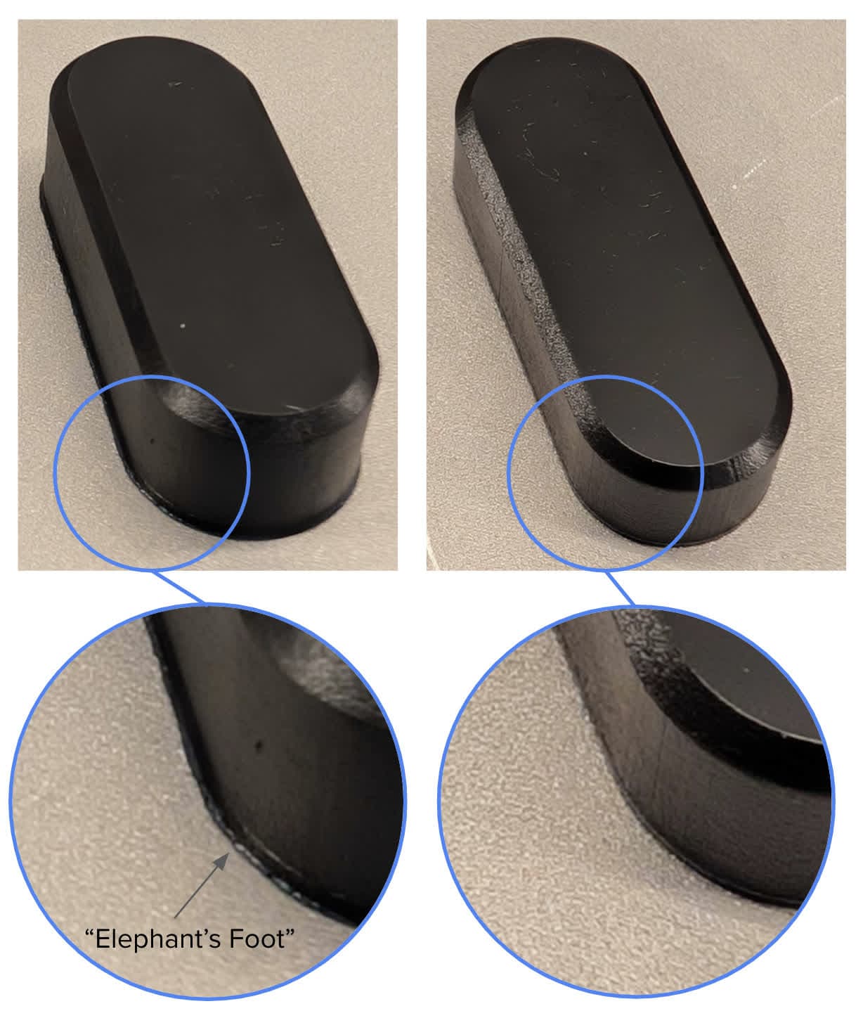
Example: Removing build platform flashing from parts printed in ESD Resin on a Form 4

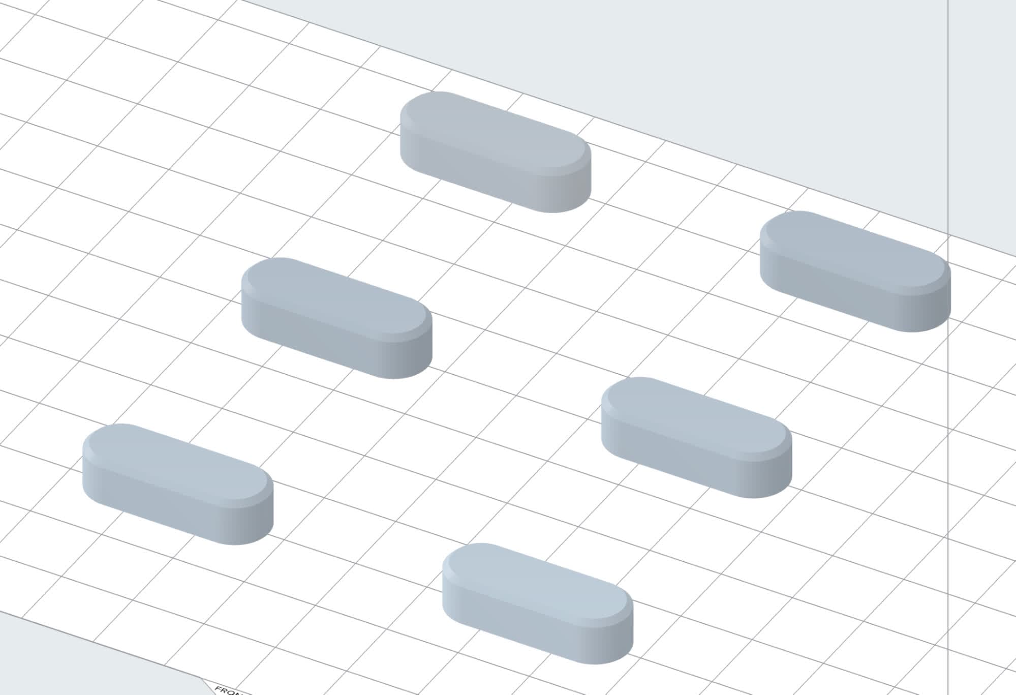
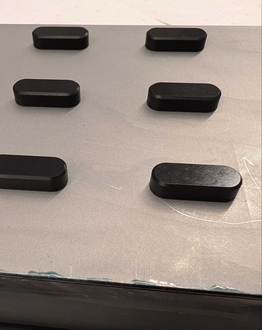
Many parts printed in ESD Resin have a small brim at the edges caused by high exposure at the first layer. However, small parts, such as the blocks shown below, do not have a large buildup of curing-related stresses that can cause them to shrink and peel off of the build platform. Build platform flashing can also cause issues with fitment if your printed parts are part of a larger assembly.
Set of models to be printed in ESD Resin shown in PreForm

For this example, a single print was done with the blocks shown above. After printing, they showed a small amount of flashing along the build platform. This can be corrected using the Early Layer Exposure and Offset array field in the Print Settings Editor based on the amount of excess material around the base of the part.

Once the part was cleaned, removed from the build platform, and post-cured according to Formlabs recommendations, the flashing was measured along the part with a micrometer. In this case, the body of the part was 9.53 mm in width, while the flashing measured 9.821 mm in width.

Part printed in ESD Resin
Measuring build platform flashing on a printed part

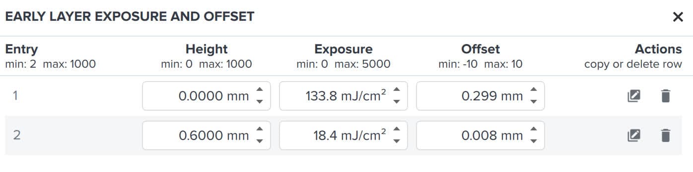
To get the desired offset, subtract the desired part width from the width of the flashing. Here, 9.821 mm - 9.53 mm = 0.291 mm. Add this to any preexisting offset in the first entry in the Early Layer Exposure and Offset array field. Here, the default offset was 0.008 mm, so the new offset is (0.291 mm / 2) + 0.008 mm = 0.154 mm. The field accepts offset values with up to three decimal places, so round the result if necessary.

Adjusting Early Layer Exposure and Offset based on test print measurements

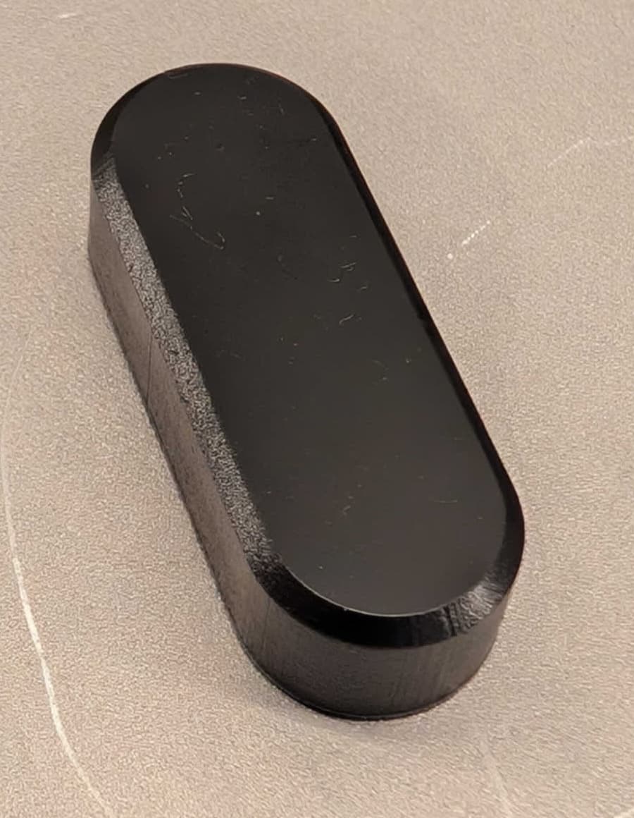
After reprinting with the new print setting, the parts showed nearly no flashing along the build platform, greatly reducing post-processing times.

ESD Resin part reprinted without build platform flashing