
Low-Volume Rapid Injection Molding With 3D Printed Molds
This white paper provides methods and guidelines for using stereolithography (SLA) 3D printed molds in the injection molding process to lower costs and lead time. Through the real-life case studies with Braskem, Holimaker, and Novus Applications, you’ll learn how this hybrid manufacturing process enables on-demand mold fabrication to quickly produce small batches of thermoplastic parts.
Introduction
Injection Molding
Injection molding is one of the leading processes for manufacturing plastics. It is widely used for mass-producing identical parts with tight tolerances. It is a cost-effective and extremely repeatable technology that yields high-quality parts for large series. It can produce volumes from 1,000 to 100,000+ parts at very low unit costs. Injection molding has a short cycle time, with each machine capable of building new parts every 15 to 60 seconds. It is a fast, intensive process where high heat and pressure are involved to melt thermoplastic and force it inside a mold.
Because of these extreme molding conditions, the tools are traditionally made out of metal by CNC machining or electric discharge machining (EDM). These are expensive industrial methods that require specialized equipment, high-end software, and skilled labor. As a result, the production of a metal mold typically takes four to eight weeks and costs anywhere from $2,000 to $100,000+ depending on the shape and the complexity of the part.
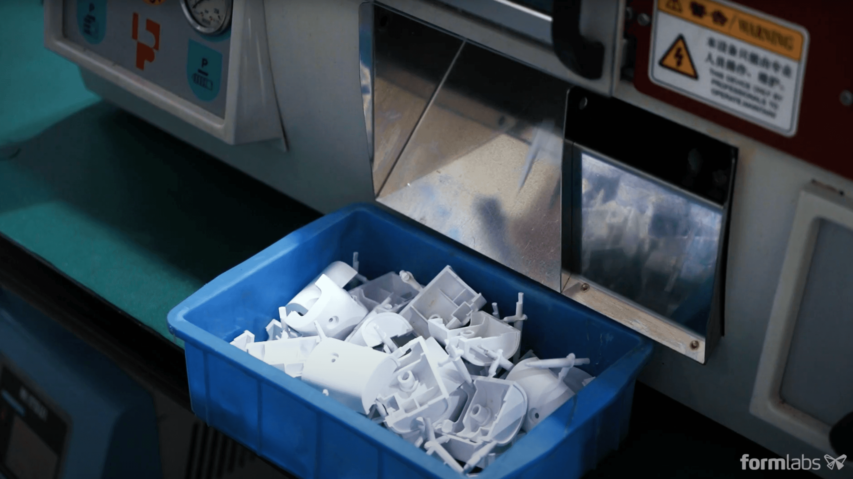
For smaller part quantities, the cost, time, specialized equipment, and skilled labor required to fabricate the mold out of common tooling metals and using traditional manufacturing methods often makes injection molding at this scale unobtainable. However, there are alternatives to machining molds out of metal. Leveraging 3D printing to fabricate injection molds for prototyping and low-volume production significantly reduces cost and time compared to metal molds, while still producing high-quality and repeatable parts.
3D printing is a powerful solution to fabricate injection molds rapidly and at a low cost. It requires very limited equipment, saving CNC time and skilled operators for other high-value tasks in the meantime. Manufacturers can benefit from the speed and flexibility of in-house 3D printing to create the mold and couple it with the production force of injection molding to deliver a series of units from common thermoplastics in a matter of days. Product development teams benefit from the ability to iterate on the design before investing in hard tooling. They can even achieve complicated mold shapes that would be difficult to manufacture traditionally, enabling designers and engineers to be more innovative. 3D printed molds can also be easily replaced as the design evolves and in case of failure.
Even though 3D printing molds can offer these advantages when used appropriately, there are still some limitations. We should not expect the same performance from a 3D printing polymer mold as from a machined metallic one. Critical dimensions are harder to meet, cooling time is longer because the thermal transfer occurs slower in plastic, and printed molds can easily break under heat and pressure. However, companies across multiple industries are continuing to implement 3D printed molds into their short-run injection molding workflows, enabling them to quickly produce hundreds to thousands of parts. From designing functional prototypes with enduse materials, to fabricating parts during pilot production, or manufacturing end-use parts, 3D printing injection molds is a cost-effective and quick way to produce parts in limited quantities.
Book a Consultation
Get in touch with our 3D printing experts for a 1:1 consultation to find the right solution for your business, receive ROI analyses, test prints, and more.
Fast Fabrication of Low Volume Injection Molds
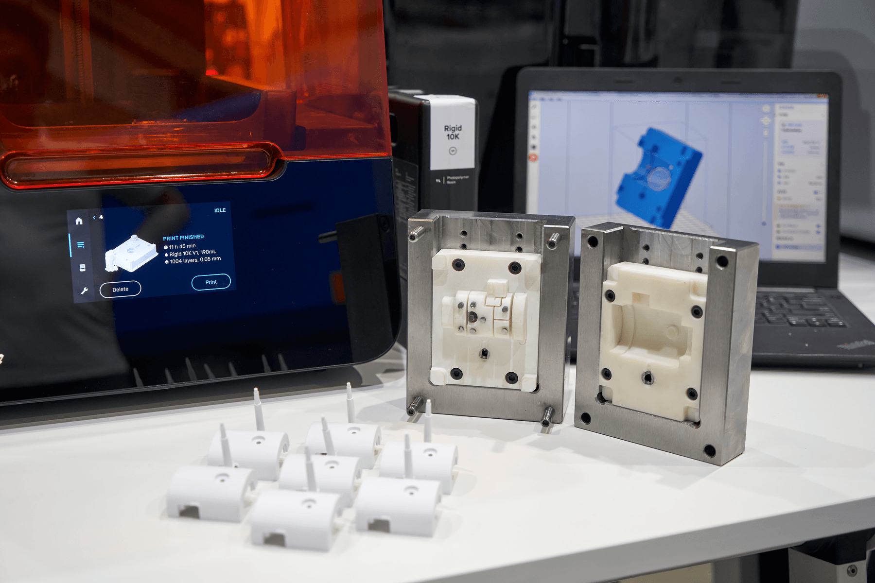
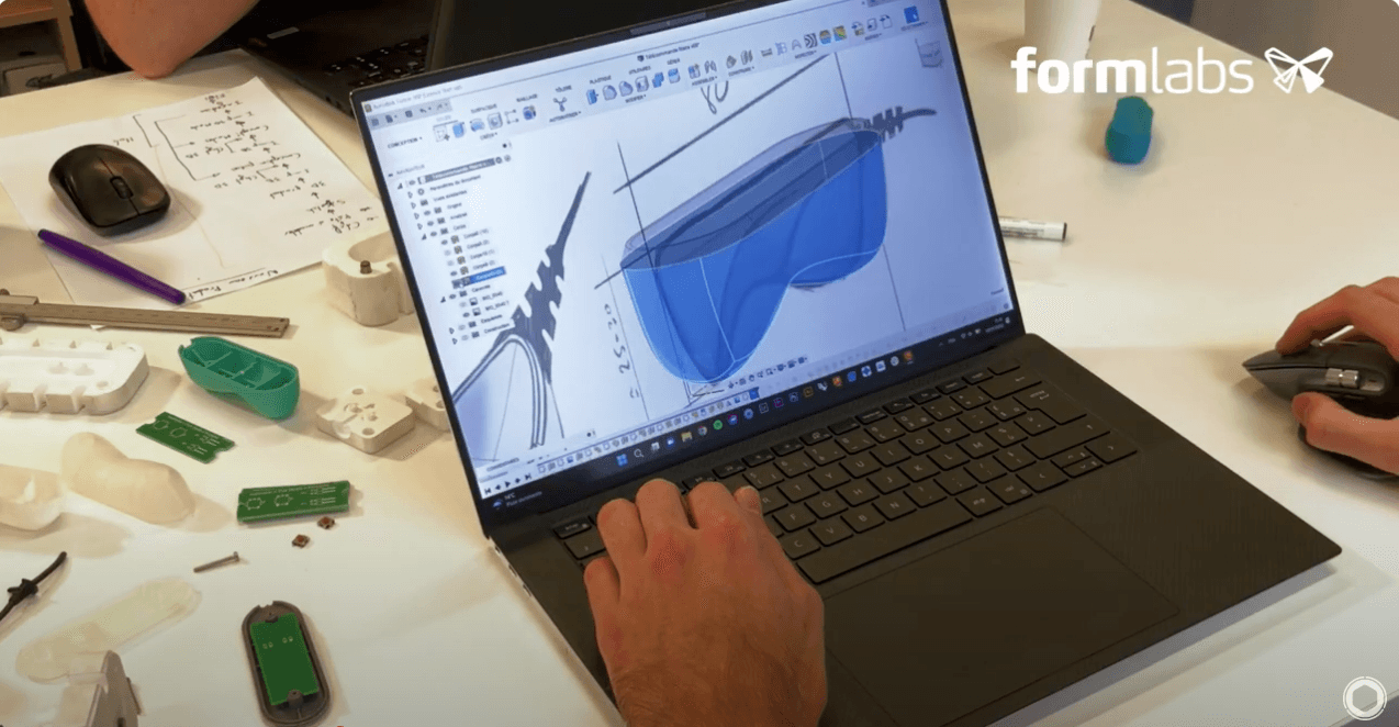
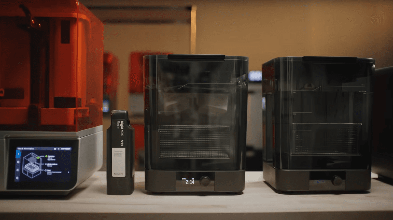
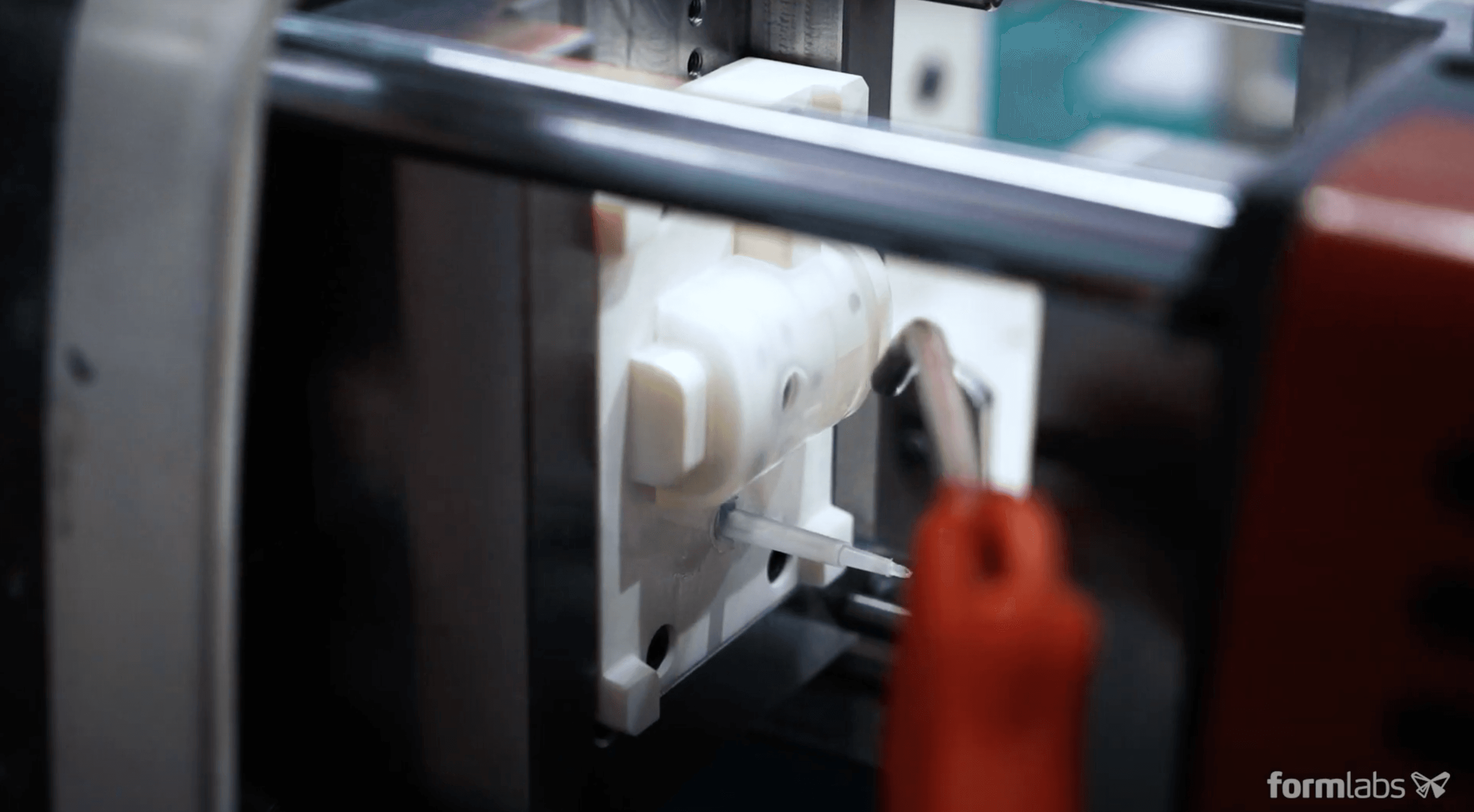
Stereolithography (SLA) 3D printing technology is a great choice for molding. It is characterized by a smooth surface finish and high precision, that the mold will transfer to the final part and also facilitates demolding. 3D prints produced by SLA are chemically bonded such that they are fully dense and isotropic, producing functional molds at a quality not possible with fused deposition modeling (FDM) 3D printers. Desktop and benchtop SLA printers, like those offered by Formlabs, simplify workflow as they are easy to implement, operate, and maintain.
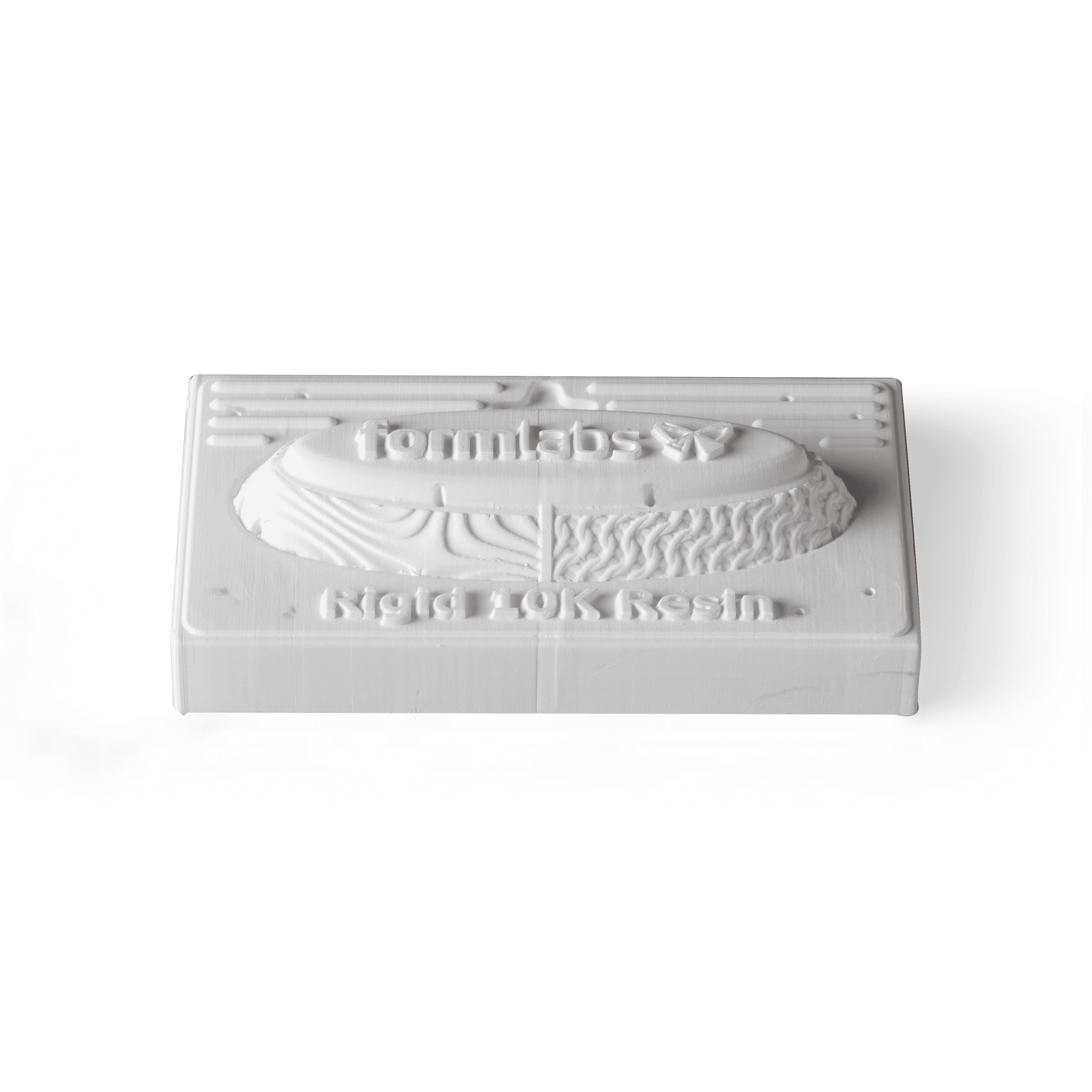
Rigid 10K Resin is Formlabs' go-to material for printing sophisticated molds for injection molding, which we will showcase with three case studies in this report. French industrial technical center IPC ran a research study and printed thousands of parts, contract manufacturer Multiplus uses it for low volume production, and product development company Novus Applications has injected hundreds of intricately threaded caps with a single Rigid 10K Resin mold.
This report will also go through a case study with Braskem, a petrochemical company that ran 1,500 injection cycles with one mold insert printed with High Temp Resin to produce mask straps. The company printed the insert and placed it inside a generic metallic mold integrated into the injection system. Our final case study with French startup Holimaker proposes a desktop injection molding workflow to produce dozens of parts using various resins.
This white paper will first share a table of data gathering dozens of molding conditions from users. It will also propose a process overview to get started quickly with 3D printed injection molds. Then, it will dive into the step-by-step method and give a general overview of the workflow, design guidelines, and best practices for 3D printing molds for injection molding. Finally, it will go into the details by covering five case studies on how each firm found success with its 3D printed molds.
Get Started with 3D Printing
Formlabs' complete, easy-to-use ecosystem makes it simple to get started with 3D printing. Explore our 3D printers and materials to find the right fit for your needs.
Data Collection: Injected Materials, Temperatures, and Other Process Conditions
Injection molds fabricated with Formlabs 3D printers have been tested with both desktop and industrial injection molding machines under a wide range of conditions. These low-volume molds are capable of withstanding hundreds to thousands of shots, depending on several factors, including the part design, mold and injection materials, molding parameters, and any coolants or demolding agents used.
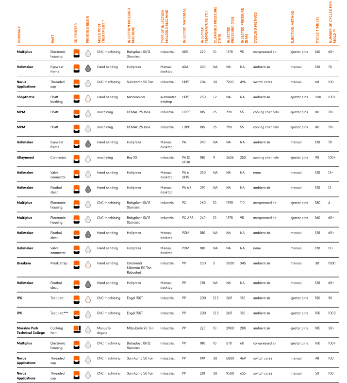
The following table gathers data from Formlabs users using 3D printed molds for their activities. It includes process conditions such as injected material, injected temperature, injected pressure, cycle time, and number of cycles per mold.
Method
Process Overview
1. Mold Design
1.1. Part Design
1.2. Mold Design
2. Mold 3D Printing
2.1. Choosing Rigid 10K Resin
2.2. File Preparation Before Printing
2.3. Washing, Drying, and Removing Supports
2.4. Optional Machining
2.5. UV and Thermal Post-Curing
2.6. Optional Media Blasting
3. Mold Assembly and Finishing
3.1. Installing the Mold Inside a Metal Frame
3.2. Optional Mineral Oil and Mold Release
3.3. Optional Coating
4. Injection Molding
4.1. Clamping 4.2. Injection
4.3. Cooling
4.4. Demolding
What to Expect From a 3D Printed Injection Mold
There are a few things you should take into account when using 3D printed injection molds:
-
Dimensional accuracy of the mold: It is important to note that the dimensional accuracy of a 3D printed polymeric tool may not be as good as a metal machined tool. However, it is possible to post-process (sand or machine) the 3D printed molds to reduce size variations.
-
Breakage or cracking of the mold under pressure and heat: 3D printed molds typically have a shorter lifetime than metal molds and, therefore, are recommended for lower volume production.
-
Cycle time: the cooling time is longer than with a metallic mold, as the thermal transfer occurs more slowly in plastic parts. Cooling methods, such as using compressed air, can help reduce cycle time with 3D printed molds.
-
Demolding process: Adhesion of the part to the mold can cause deterioration of the mold during extraction. Demolding agents can be used to assist with this part of the process.
-
Flashing may occur and slow down the demolding step. This is an excess of material coming out of the mold during the injection when the mold is overfilled, or if the parting plane is not perfectly flat.
These issues can be mitigated by reducing the injection pressure, changing the CAD file, or adapting the demolding process. These three parameters will largely influence the success of the operation.
The type of injection press does not have a significant influence on the process. Automated small-scale injection molding equipment, such as the desktop machine Micromolder or the hydraulic machine Babyplast 10/12 are good solutions for producing small parts. If you are new to injection molding and are looking into testing it with limited investment, using a benchtop manual injection molding machine such as the Holipress or the Galomb Model-B100 is a good option. Some of our customers have recommended systems from Minijector, Morgan, or APSX as well.
A broad range of thermoplastics can be injected with 3D printed molds, such as acrylonitrile butadiene styrene (ABS), acrylonitrile styrene acrylate (ASA), polyamide (PA), polycarbonate (PC), polyethylene (PE), polyoxymethylene (POM), polypropylene (PP), thermoplastic elastomer (TPE) or thermoplastic polyurethane (TPU). A low viscosity material will help reduce the pressure and extend the lifetime of the mold. You should also consider:
-
PP, PE, and TPE are easy to process at hundreds of cycles.
-
In contrast, more technical plastics like PA or PC will allow a lower number of runs.
-
TPUs are challenging to process as they might adhere to the 3D printed mold.
Using a release agent can help to separate the part from the mold. Injection molds fabricated with Formlabs 3D printers have been tested with both desktop and industrial injection molding machines using a wide range of pressures, temperatures, and materials. Read our information sheet to see the process conditions used by various users. The complexity of the injection molding process is mostly driven by the complexity of the part and the mold structure. Let’s review workflow with guidelines and best practices.
Request a Free Sample Part
See and feel Formlabs quality firsthand. We’ll ship a free 3D printed sample part to your office.
Workflow
1. Mold Design
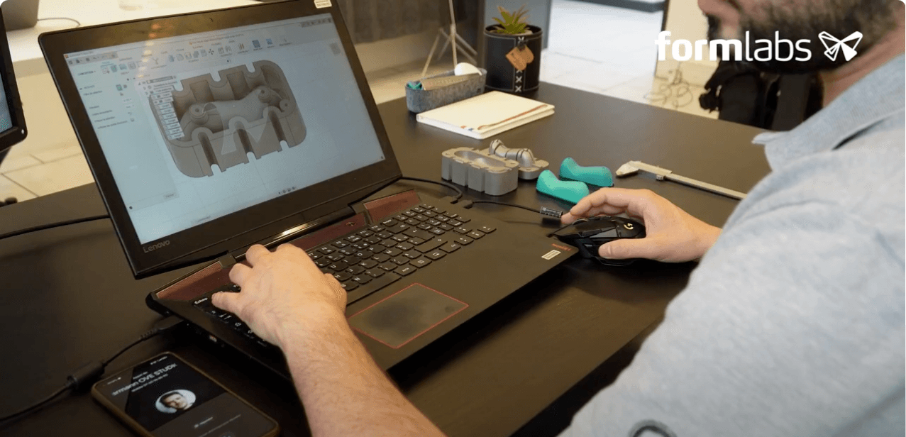
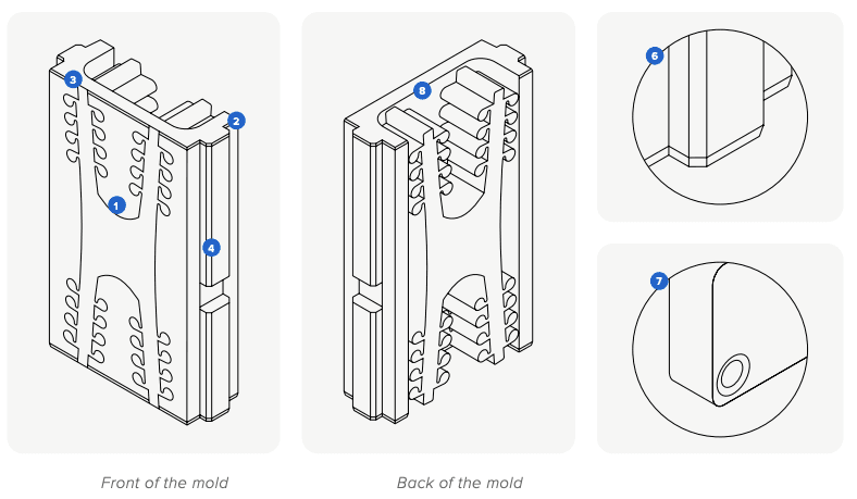
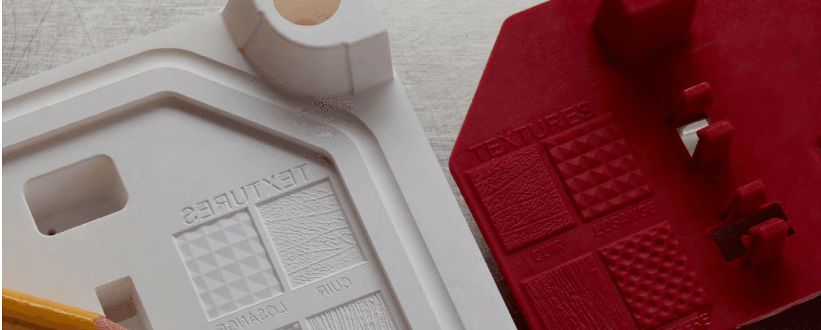
Design the mold for your part in the CAD software of your choice. When designing an injection mold that is to be 3D printed, common design for manufacturing principles should be followed. It is good practice to adhere to the rules of design for additive manufacturing as well as the general rules for injection mold design, such as including three to five degrees of draft angles, maintaining a uniform wall thickness across the part, or rounding up the edges. 3D printed molds can incorporate the same components as metal molds, including side actions, inserts, or ejector pins. SLA printing also makes it possible to incorporate fine texturing in the CAD model. Here are a few helpful pieces of advice from users and experts, specific to polymer printed molds:
To optimize dimensional accuracy:
-
Plan stock allowance (min 0.5 mm) on the mold and post-process to adjust the sizes.
-
Print one set of the mold prior to production to understand dimensional deviations. Edit your CAD model to account for these deviations in your mold design.
To extend the lifetime of the mold:
-
Open up the gate to reduce the pressure inside the cavity.
-
When possible, design one side of the stack flat while the other side carries the design. This will lessen the chance of misalignment during mold clamping and reduce the risk of flashing.
-
Include large air vents (0.05 mm depth) from the edge of the cavity to the edge of the mold to allow the air to escape. This yields a better flow into the mold, minimizes pressure, and alleviates flashing in the gate area to decrease cycle time.
-
Avoid thin cross-sections: surface thickness less than 1-2 mm may deform with heat. Negative features smaller than 0.5 mm can be challenging to get a good definition on, while standing features smaller than 0.1 mm can be prone to breaking off.
-
Incorporate cooling channels if needed. Because thermal transfer occurs more slowly in plastic parts than in metal parts, a regulation system might not have enough impact on the temperature to justify the time spent designing this system. However, for large molds used at a short cycle time, cooling channels can help monitor the tool temperature.
To optimize the print:
-
Add a chamfer to help remove the piece from the build platform.
-
Build assembly features or centering pins at the corners.
-
Adjust the back of the mold to minimize material usage: reduce the cross-section in areas that are not supporting the cavity. It will save costs in resin and diminish the risks of print failure or warpage.
2. Mold 3D Printing
2.1. 3D Printing With Rigid 10K Resin
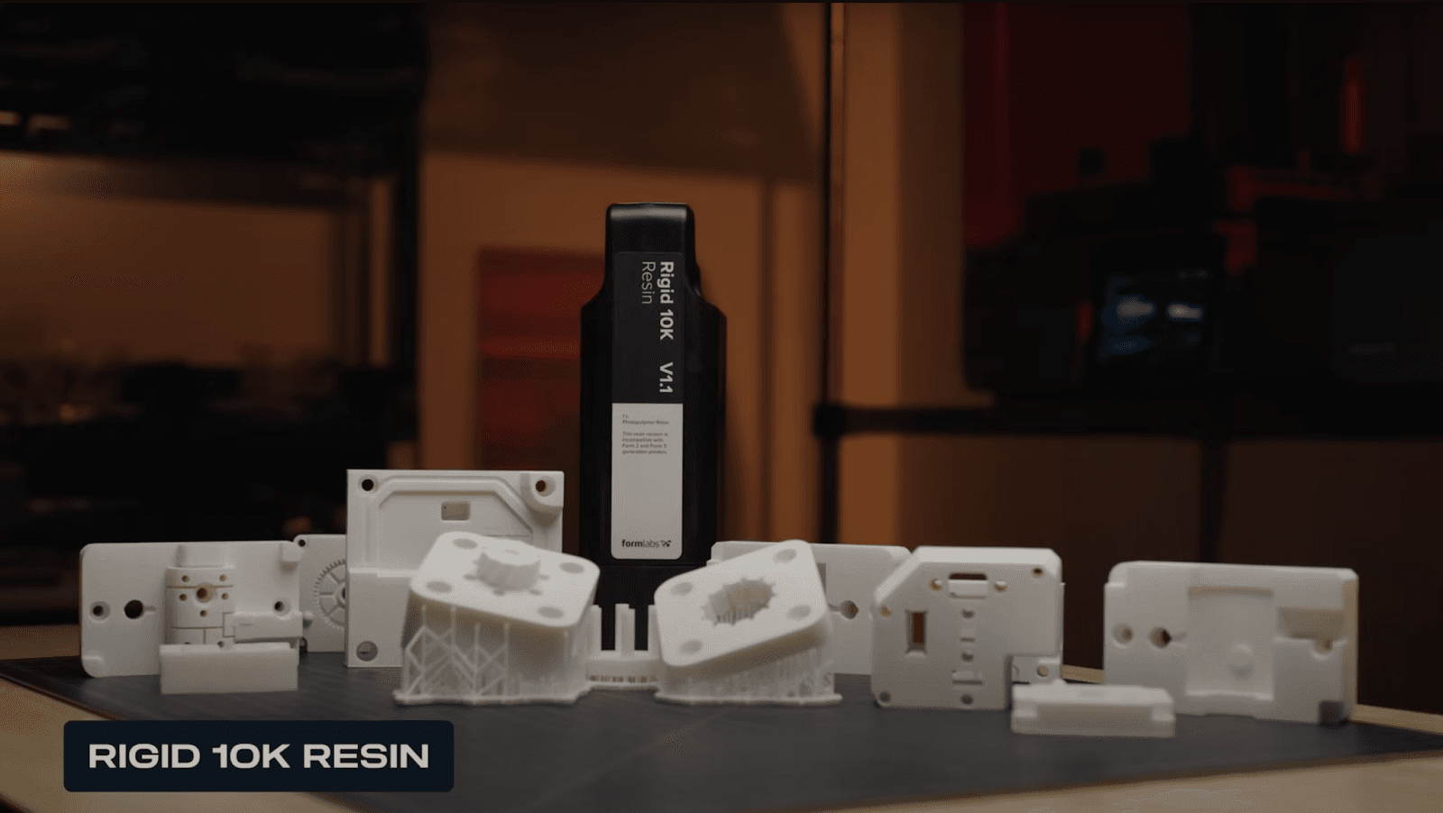
Formlabs recommends 3D printing molds with Rigid 10K Resin, because injection molding involves high heat and pressure. Formlabs Rigid 10K Resin is an industrial-grade, highly glass-filled material that serves as an ideal molding material for a wide variety of geometries and injection molding process conditions. Rigid 10K Resin has a heat deflection temperature (HDT) of 218 °C @ 0.45 MPa and a tensile modulus of 10,000 MPa, making it a strong, extremely stiff, and thermally stable molding material that will maintain its shape under pressure and temperature to produce accurate parts.
High Temp Resin is a material that can be considered as an alternative to Rigid 10K Resin for molds. This resin has an HDT of 238 °C @ 0.45 MPa, the highest among Formlabs resins, allowing it to withstand higher molding temperatures. It can print at 25 microns layer height and will perform better on thin walls and fine details. However, molds printed in High Temp Resin are more brittle than those from Rigid 10K Resin and will break much earlier under pressure.
Rigid 10K Resin generally yields the best results for this application, though success depends on part geometry, injected material, and molding parameters. Alternatively, High Temp Resin can work for thin walls but is more brittle, while General Purpose Resins offer a cost-effective solution for small parts and low cycles.
2.2. File Preparation for Printing
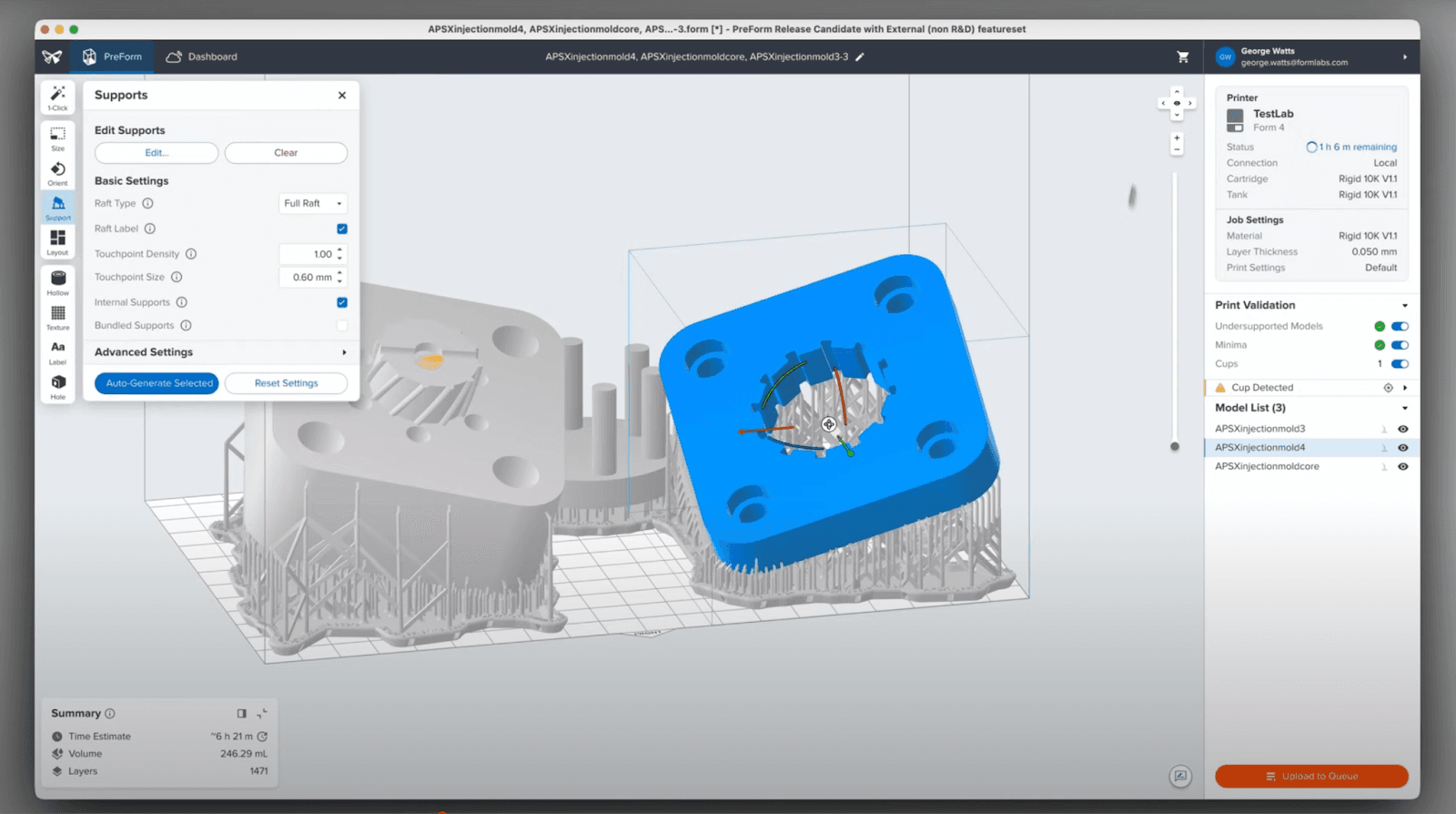
Export the STL file of your mold and upload it into PreForm, Formlabs print preparation software:
-
Select a layer height of 50 microns. Smaller layer heights typically result in greater dimensional accuracy and a finer surface finish. A smoother surface finish may help reduce adhesion from the injected material to the mold.
-
Next, strategically orient your mold, following Formlabs’ print orientation guide. Minimizing the amount of flat area in the XY plane will help reduce warping and curling of thin segments or large flat surfaces, so for these features, Formlabs recommends that the mold be tilted. For thicker and blockier models, this is less of a concern. Angling your mold can also help minimize the amount of supports needed on critical mold surfaces.
-
Ensure you support any free-hanging cores, especially small diameter ones, but avoid placing supports on molding surfaces. Support generation is essential for overhangs and for lifting the part off the build platform to prevent cupping. Increasing support density will also help to minimize warping.
-
When possible, print both halves aligned in reference to the build direction. Potential size variations will be more consistent, improving the quality of the parting line.
-
Print multiple cores in case of breakage. Employ interchangeable stacks to run new cycles while the other sets cool in order to decrease the cooling time and compensate for the low thermal conductivity of a plastic mold.
Send the print job to the printer and start your print.
2.3. Washing, Drying, Removing Supports
After your print finishes, thoroughly wash your parts in IPA with the Form Wash to remove all uncured resin. Because Rigid 10K Resin contains glass particles, Formlabs advises maintaining a wash bucket separate from other resins.
-
Run a first wash cycle of 10 minutes to remove the bulk of resin.
-
Perform another 10-minute wash cycle in a second Form Wash with clean solvent.
-
You can use a syringe or wash bottle filled with IPA, followed by compressed air, to ensure liquid resin is flushed out of any internal channels.
During the wash, a small amount of IPA will soak into and swell your parts. For best results, make sure your parts are fully dried before post-curing, or the entrained IPA may cause stains or cracks at the surface. At room temperature drying will take 3-4 hours, but this process can be sped up by heating your part in the Form Cure.
After your parts are washed and dried, you can then remove the supports and sand off the support marks with sandpaper if needed.
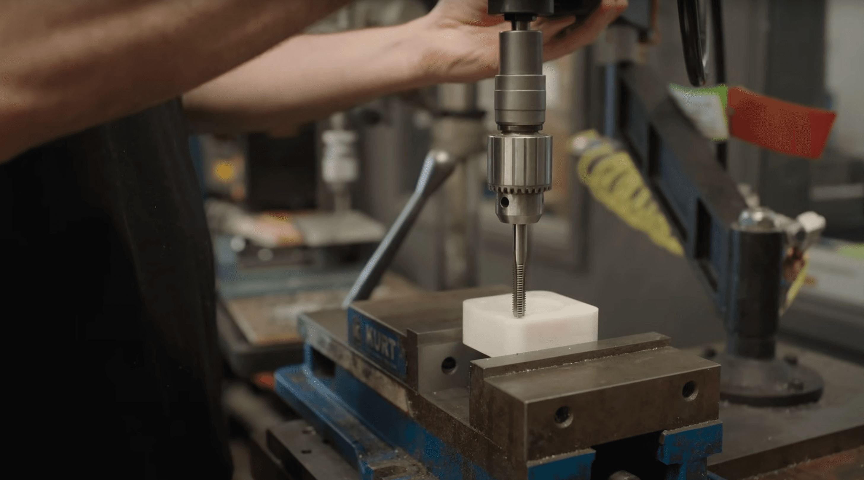
2.4. Optional Machining
Machining can be performed to refine critical features and ensure a good fit, in particular diameters and outer surfaces. This would include finishing gating, vents, and ejector pinholes, or grooming outer edges for assembly.
Rigid 10K Resin can be machined using standard CNC or manual milling equipment. Formlabs recommends using Masonry drill bits at low RPM and feed rates, as you might use for a ceramic material. Machining can also be performed after post-curing, however, it is more likely to cause chipping and cracking, especially for tapping and drilling operations.
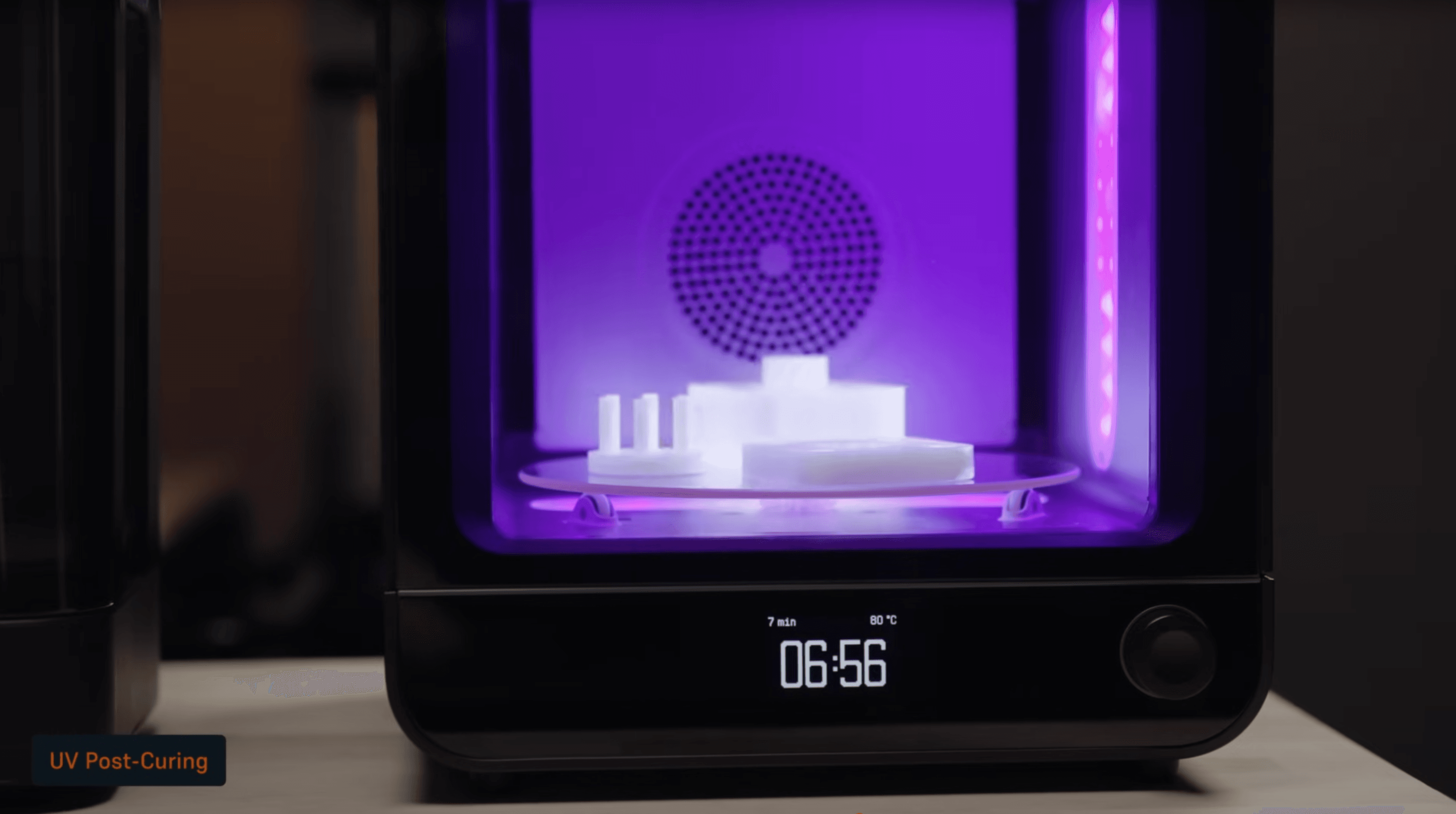
2.5. UV and Thermal Post-Curing
Post-curing ensures 3D printed parts reach their optimal mechanical properties:
-
Formlabs recommends UV-curing your Rigid 10K Resin mold for 7 minutes at 80 ˚C with a 3-minute preheat in the Form Cure.
-
Additionally, thermal-curing your mold in an oven for 125 minutes at 90 °C.
You can help minimize warpage during post-cure by placing your mold inside the Form Cure before it starts heating, so that it reaches a more even temperature during UV-curing. You can also clamp your mold during curing to mitigate warping, especially for large molds.
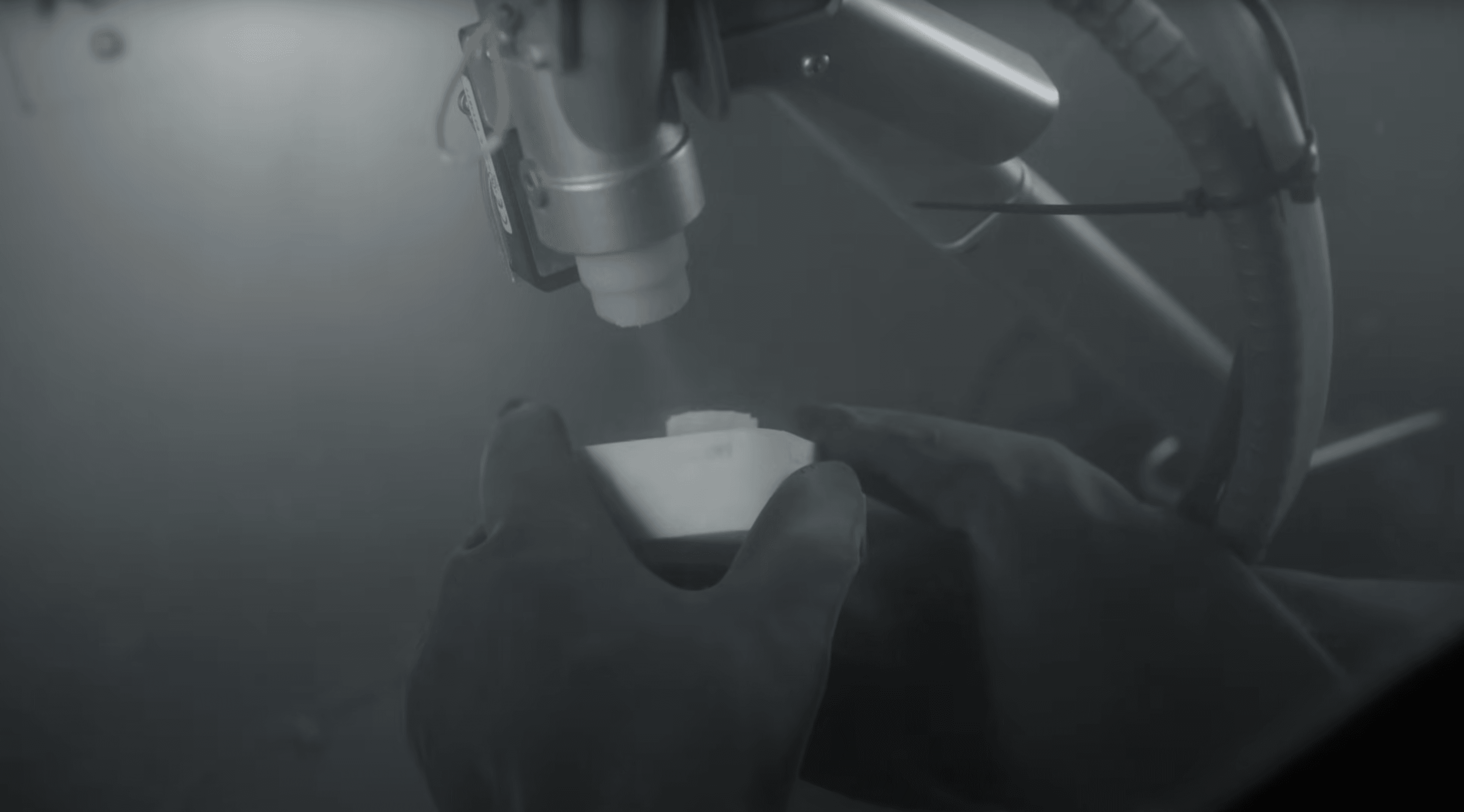
2.6. Optional Medial Blasting
For parts printed in Rigid 10K Resin, Formlabs also recommends media blasting to further improve mechanical properties. This is an optional step, but after extensive research and testing, media blasting Rigid 10K Resin appears to increase material strength across every metric. Test specimens were media blasted with 70 to 140 mesh glass beads on all surfaces at an air pressure of 90 psi.
Media blasting may also improve mold performance in several ways. Smoothing the mold surface will reduce defects that could cause part failures, and may help to decrease required injection pressures. It will also improve surface finish and reduce the adhesion of the injected material to the mold. The process of media blasting changes the surface color of Rigid 10K Resin parts from white to cream, but if done carefully, it will not significantly affect part dimensions. Pay attention to the surface color as you blast to know when you have removed enough material.
You can use the Fuse Blast or any other standard media blasting cabinet. A final rinse or wipe with IPA to remove any remaining particulate might be beneficial, followed by thorough drying, especially if you plan on applying any coatings afterwards.
3. Mold Assembly and Finishing
3.1. Installing the Mold Inside a Metal Frame
After machining, post-curing, and media blasting, Formlabs recommends installing your mold inside a metal frame. This frame helps to absorb some of the pressure and temperature during the injection molding process, which could significantly extend the mold's lifespan. Standard aluminum frames are readily available from injection molder manufacturers. Another option could be to use a metallic modular mold base system, such as the Master Unit Die QuickChange or similar solutions, allowing you to quickly switch and replace printed mold inserts.
3.2. Optional Mineral Oil and Release Agent
Without media-blasting, the surfaces of parts printed in Rigid 10K Resin may feel powdery. Rubbing mineral oil or water into your part’s surface and wiping away any excess will lead to a smoother, less powdery finish.
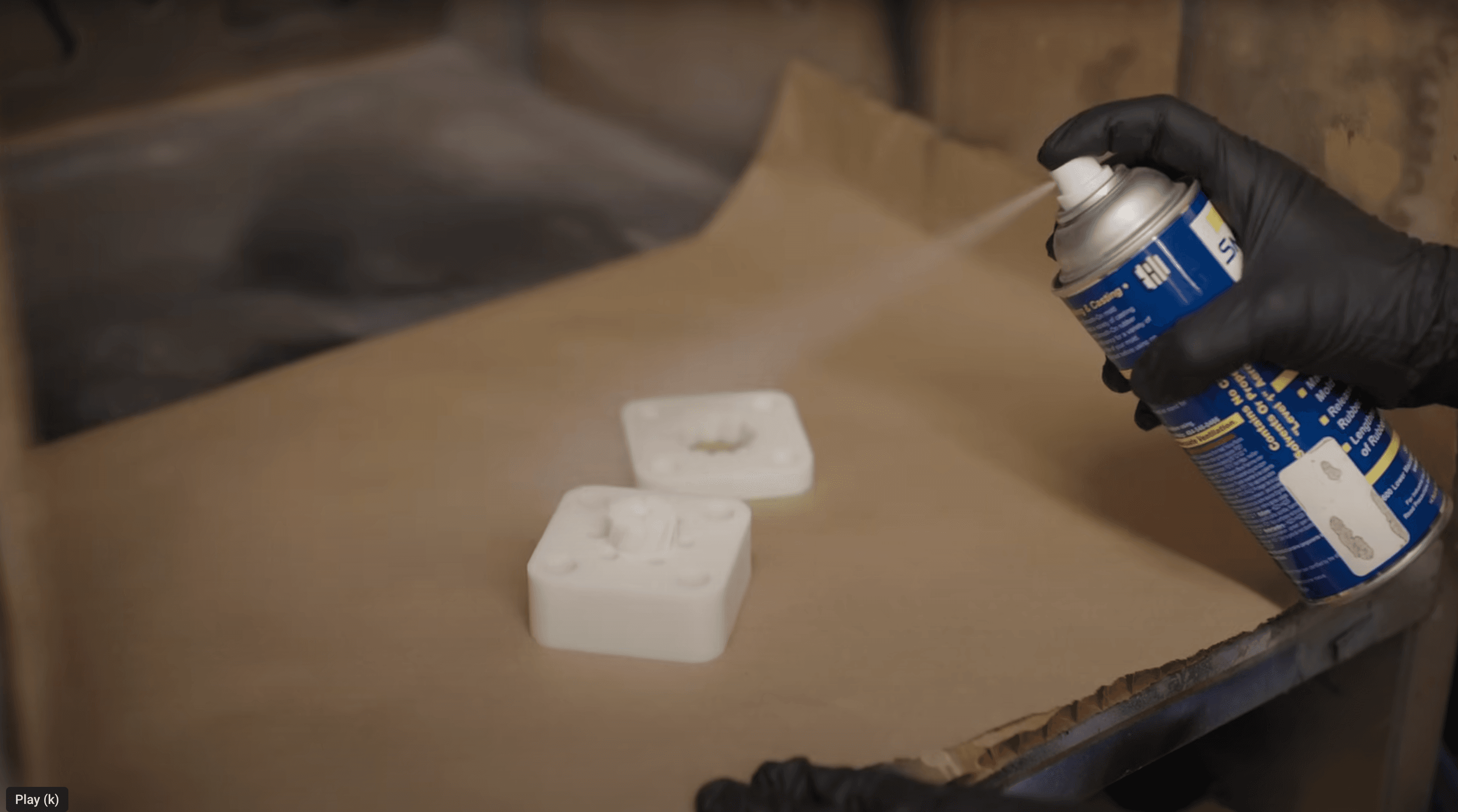
When your mold is assembled, you can apply a standard mold release spray to improve demolding, especially if you are injecting viscous material like TPU. Mold release is widely available, and silicone mold releases are compatible with Grey Pro Resin, High Temp Resin, and Rigid 10K Resin. Novus Applications uses solutions from Slide and Braskem uses the MR303 silicone food-grade release agent from Sprayon.
3.3. Optional Coating
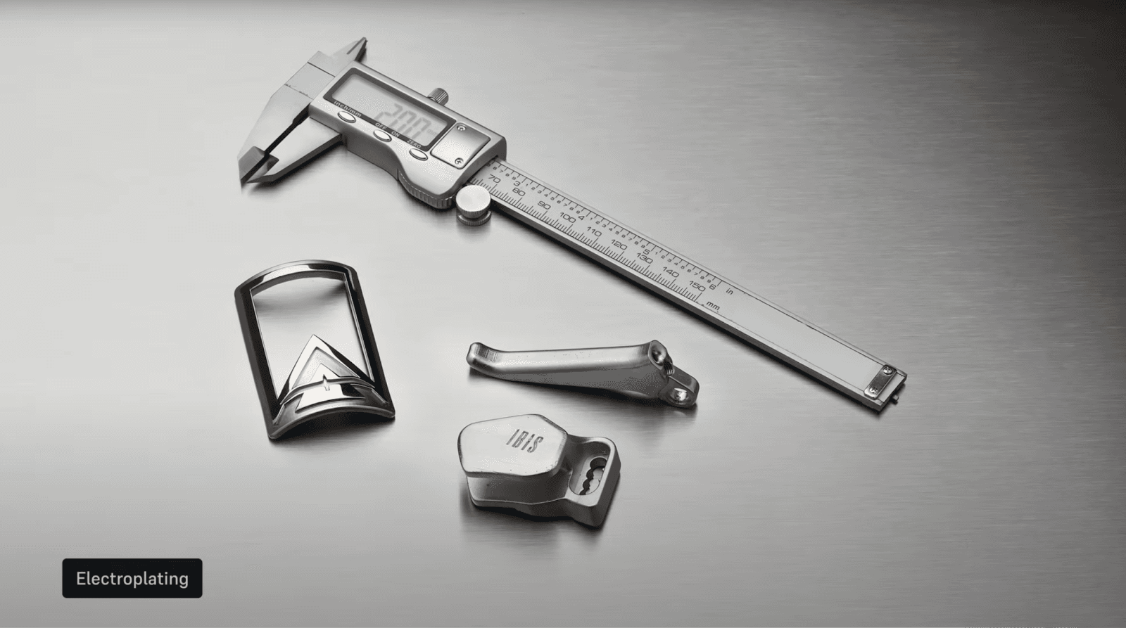
More advanced coating methods are available for those seeking to push the performance of their 3D printed molds even further. Ceramic coatings such as Cerakote, for example, offer exceptional hardness, chemical resistance, and high-temperature resistance. Various polymer coatings, such as epoxies or polyurethanes, can improve surface smoothness and provide a protective layer against abrasion or chemical interaction with the injected material.
Lastly, electroplating could provide a true metallic surface that dramatically boosts durability and conductivity. While these options have not undergone exhaustive testing by Formlabs yet, Formlabs encourages users to explore these options to find the one best suited to their needs. For some starting points and more information, please see the details below this video.
4. Injection Molding
4.1. Mold Clamping
Insert the plastic pellets, input the required settings, and begin production. A lower clamping force is suggested, particularly if the printed mold is not protected by a metal frame. A broad range of thermoplastics can be injected with 3D printed molds, such as TPE, PP, PE, ABS, POM, ASA, PA, PC, or TPU.
4.2. Injecting
It may take a few shots to identify your ideal process conditions, as many factors are at play, including part geometry, choice of plastic, injection temperatures and pressures, and other parameters. Reduce injection pressure and temperature as much as possible.
With one printed mold, Formlabs users are usually injecting 100s of parts in easy-to-process plastics such as TPE, PP, and PE with temperatures up to 250°C. With plastics that require higher injection temperature, such as PA or PC, the 3D printed mold might have a shorter lifespan. Read our process conditions documentation to see test results with both desktop and industrial injection molding machines.
4.3. Cooling
The cooling time of a polymer printed mold is longer than that of a metal mold, as thermal transfer occurs more slowly in plastic than in metal. Maintain the tool temperature below 60°C ideally. Cooling can be accelerated by:
-
Letting the mold cool in ambient air and using interchangeable stacks if speed is critical.
-
Applying compressed air to cool the mold.
-
Incorporating cooling channels in the design.
4.4. Demolding
Demold the part either manually or automatically with ejector pins. Apply a release agent for thermoplastics with high viscosity.
How to Use 3D Printed Injection Molds for Low-Volume Production
Watch our video to see how you can produce parts with 3D printed injection molds.
Case Studies
In this section, we will go through the case studies from Multiplus, IPC, Novus Applications, Braskem, and Holimaker.
Multiplus Injection Molded Hundreds of PP and ABS Parts for Electronic Housing in Three Days
This case showcases how Multiplus, a Shenzhen-based contract manufacturer uses molds printed in Rigid 10K Resin to manufacture parts in PP, ABS, PC-ABS, and PC materials.
Background and Challenge
In the years after joining the World Trade Organization (WTO) in 2001, China quickly became the world's largest manufacturer in terms of output. Much of this manufacturing power comes from the Pearl River Delta region, a group of nine cities in the southern Guangdong Province that includes Shenzhen. In 2020, the region accounted for roughly one-third of China’s trade value.
Propelled by this rapid growth, many small workshops grew into international companies. Founded in 2005 in Shenzhen, Multiplus started as a micro injection molding workshop and quickly grew into a solutions provider that covers the entire production cycle from design to manufacturing of plastic products, both large and small, single or multi-shot (where two or more colors or materials are injection molded simultaneously into a single mold). Today, Multiplus provides services to over 250 clients per year, including Fortune 500 companies, some of whom require small batch production.
“Although it is not the majority of what we do now, small batch production requests are becoming more common. Some are for design and functional validation, but more are becoming end-use. This makes sense because more and more companies want to test the market,” said Kevin Li, CEO of Multiplus.
3D Printing Process
A few years ago, Multiplus adopted 3D printing and has since purchased several 3D printers, mostly to print communication models and parts for design validation in different materials. As the demand for small batch production grew, Multiplus turned to 3D printing to explore different materials in an attempt to find a cost-effective way to produce cheaper plastic molds for smaller orders. Fabricating low-volume injection molds with Formlabs 3D printers reduced costs, labor, and time compared to machining aluminum molds, and could seamlessly be used with their Babyplast industrial injection molding machines.
One of the materials Multiplus tested was Formlabs Rigid 10K Resin, a glass-filled resin that is very stiff, strong, as well as heat and chemical resistant, which are necessary properties for an injection mold. Additionally, parts printed in Rigid 10K Resin on Formlabs SLA 3D printers have a smooth matte finish that translates to clean surface finishes on the injected parts.
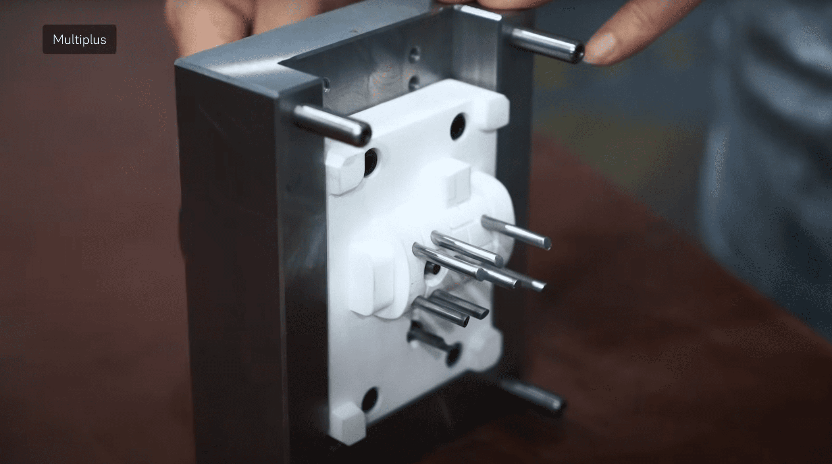
A Rigid 10K Resin mold core assembled with a metal mold shell.
“Not many 3D printed materials can withstand the repeated pressure, heating, and cooling during the injection molding process. Our experience is that even with a material claimed to withstand high temperatures, the printed mold might be able to withstand 10-20 injection cycles but would crack shortly after that, or the quality degrades so that the finished part becomes undesirable. The first batch we produced with the Rigid 10K Resin mold produced 100 parts with no issues,” said Mr. Lin Wei, Multiplus’ injection molding department manager.
Molding Process
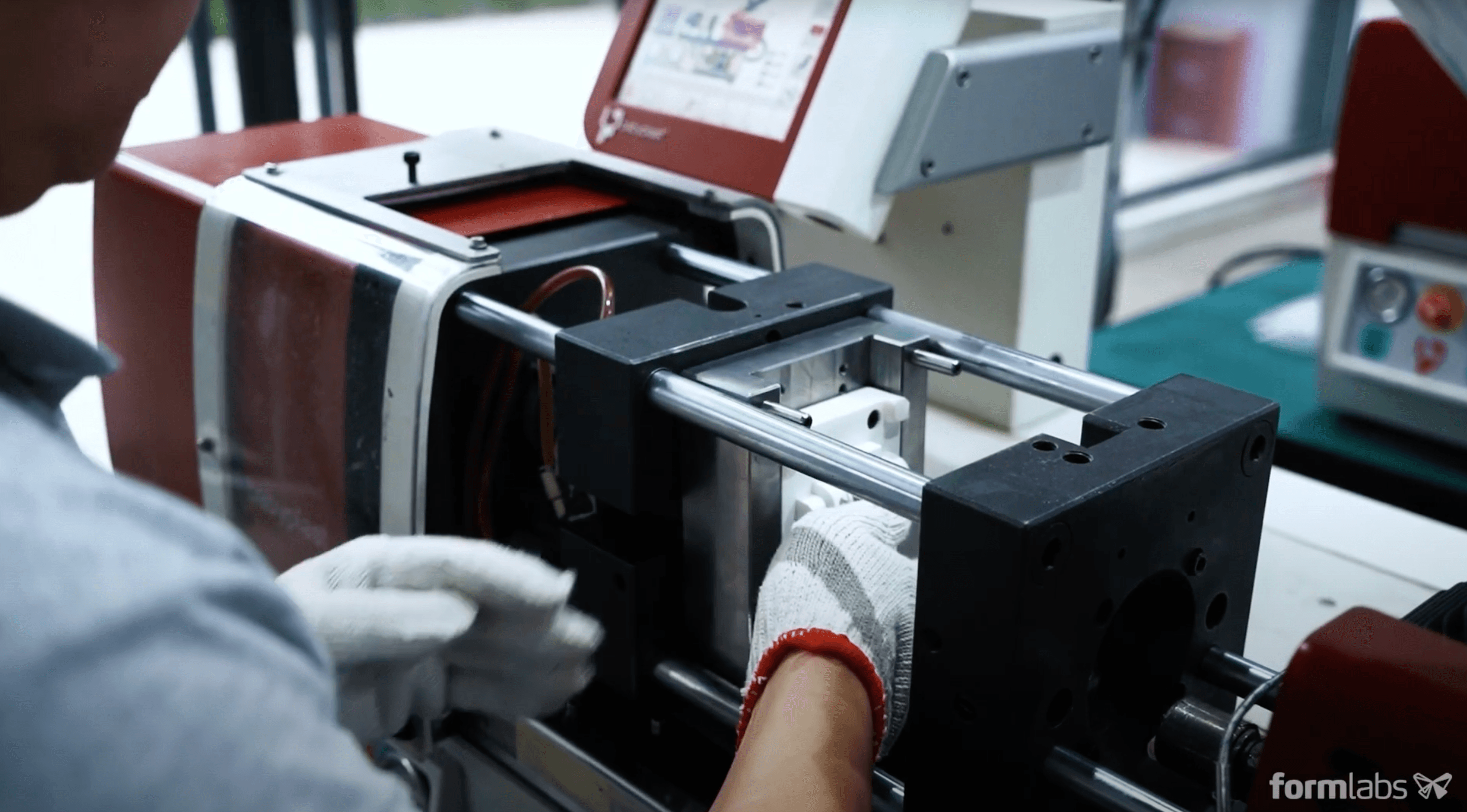
Multiplus has used their 3D printed injection molds with a Babyplast 10/12 Standard machine under a wide range of pressures, temperatures, and materials. The part tested was a control box housing for home appliances that included a few small features.
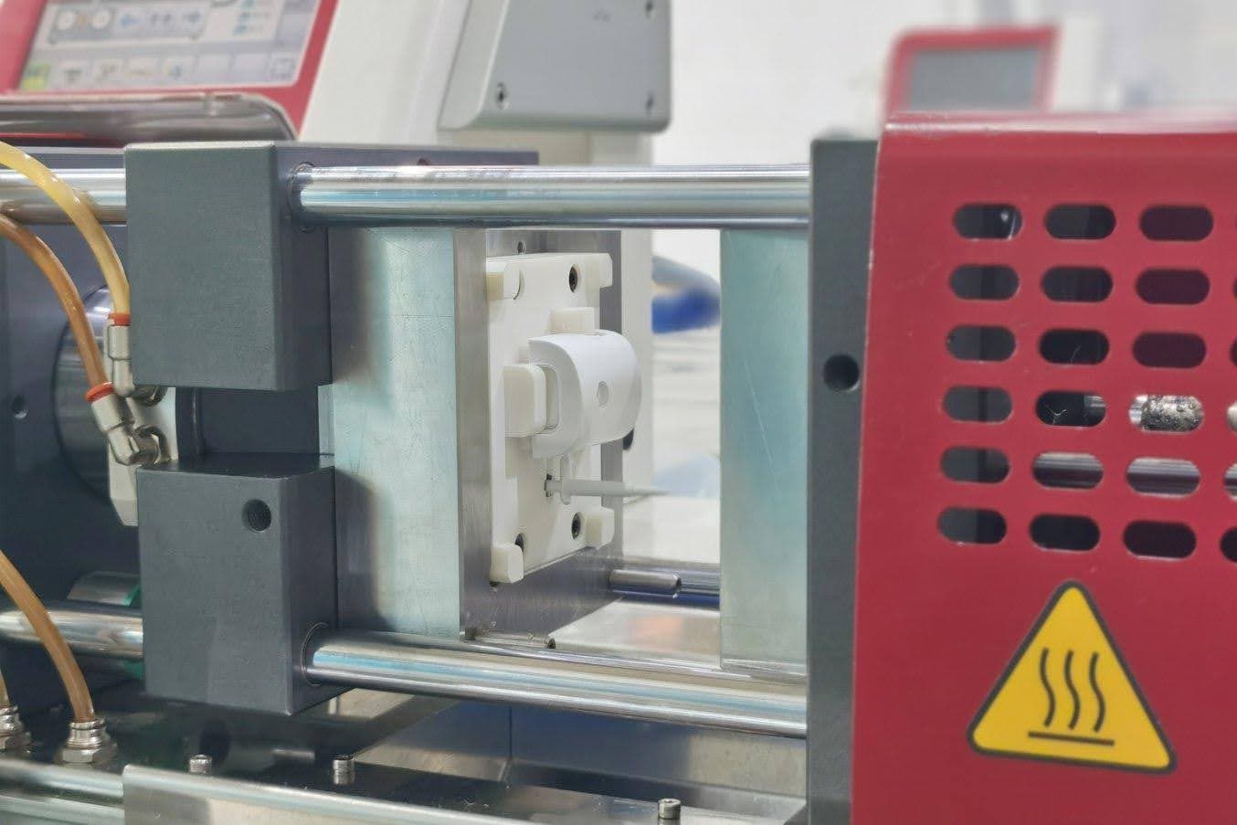
Multiplus used a Babyplast 10/12 Standard machine for molding.
From these tests, they observed that PP injected at 180°C was fairly easy to process. Multiplus obtained injected parts with good quality and a smooth surface. The printed mold ran 100 injections and was still in good condition. Similarly, ABS was processed at 220°C for 60 shots without damaging the mold. Multiplus did not test the molds to failure because of the tight production schedule, but would expect a lifetime above 100 cycles per mold for PP, ABS, and PC-ABS.
Trials with PC at 260°C led to mold breakage after only four iterations. This shows that plastics above 250°C with high viscosity are challenging to process with a Rigid 10K Resin 3D printed mold, in particular for this geometry with thin walls. High Temp Resin has a higher heat deflection temperature and can be considered as an alternative material when clamping and injection pressures are not too high.
|
Material |
PP |
ABS |
PC-ABS |
PC |
|
Injection Temperature (Nozzle) |
180 ℃ |
220 ℃ |
240 ℃ |
260 ℃ |
|
Injection Volume |
36 cc |
39 cc |
37 cc |
40 cc |
|
Cooling Time |
80 sec |
60 sec |
50 sec |
90 sec |
|
Injection Pressure |
60 bar |
95 bar |
95 bar |
110 bar |
|
Holding Pressure |
35 bar |
30 bar |
25 bar |
80 bar |
|
Holding Time |
0 sec |
1.5 sec |
1 sec |
2.5 sec |
|
Number of Cycles |
100+ |
60+ |
60+ |
4 |
Results
Multiplus has tested injection molding parts with ABS, PP, PC+ABS, and PC. After designing the mold, they would print and post-process the mold in a day, assemble the molds in the assembly workshop in half an hour or so and start injection molding on their injection molding machines. Once injection molding starts, it takes roughly three minutes for a part to be finished. Multiplus limits each mold to roughly 100 shots of use and prints multiples of the molds for larger order quantities.
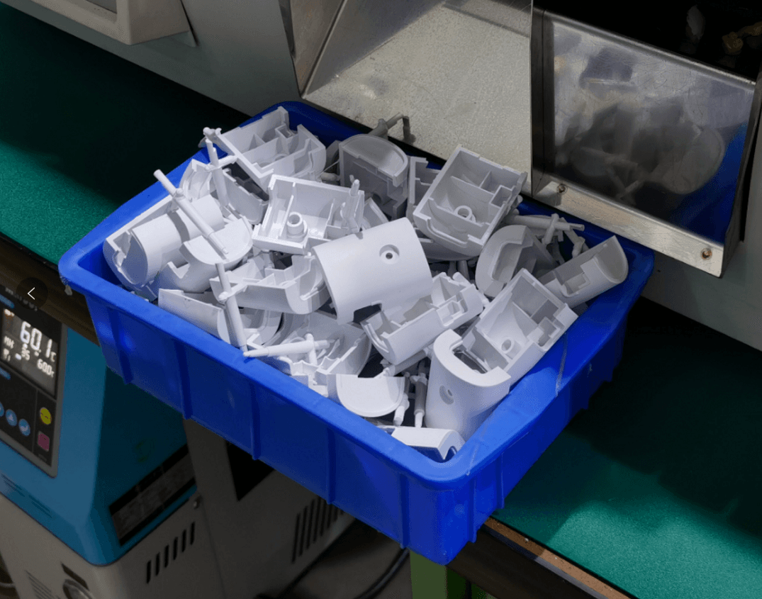
Freshly injection-molded ABS control box housings using the Rigid 10K Resin molds. The molds printed on the Form 3 could produce 60+ parts in ABS and 100+ parts in PP.
With multiple 3D printers and injection molding machines in the workshop, Multiplus can deliver hundreds of pieces as fast as three days, which is substantially shorter than the three or four weeks needed if they were to injection mold parts with a CNC machined metal mold.
|
Injection Molding 100 Parts |
SLA 3D Printed Mold |
CNC Machined Mold |
|
Lead Time |
Three to five days |
Three to four weeks |
“Having the Form 3 on our factory floor has made our mold-making process much more agile, and the Rigid 10K Resin is one of the best resins we have used so far for injection molding. Now we are able to respond to customer requests much faster,” said Kevin Li.
By seamlessly integrating 3D printing into their injection molding workflow, Multiplus was able to grow their business, take on more jobs, and be more competitive, all while reducing costs, improving turnaround time, and helping their clients bring better products to market quickly.
IPC Technical Center Injected Thousands of PP Parts with Fine Texturing
The French Industrial Technical Center for Plastics and Composites (IPC) conducted research to evaluate the usability of 3D printed molds for low-volume injection molding. This case study documents the fabrication steps and injection trials for molds 3D printed with Formlabs solution, highlighting results and best practices.
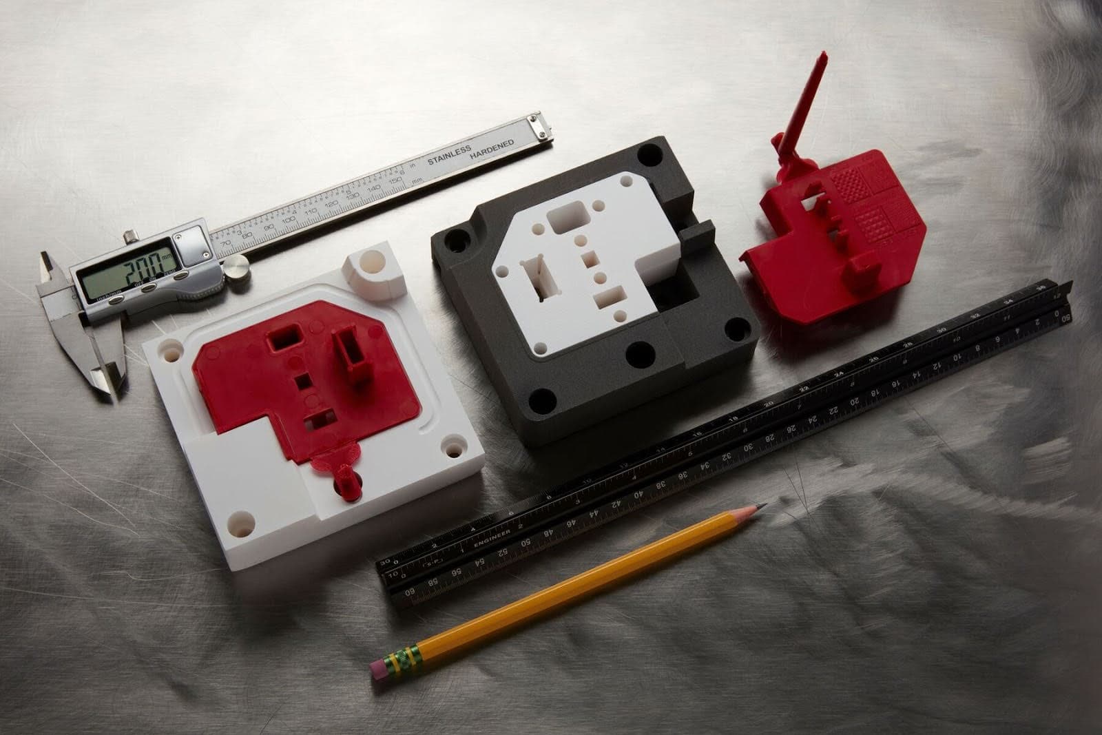
The test part was injection molded using a mold 3D printed in Rigid 10K Resin.
Background
IPC is the Industrial Technical Center whose expertise is dedicated to plastic and composite innovation in France. IPC develops new means to support all businesses, in particular small and medium-sized companies. The center works closely with European scientific key players, in order to support companies on R&D, innovation, and technology and skills transfer concerns, regardless of the process used. IPC built three technology transfer programs to tackle the major challenges of the industry. They support companies by providing R&D expertise for the circular economy (DIS 30), the additive manufacturing sector (PRINTER), industry 4.0, and for high added value products (HYPROD 2). IPC teams help industries or manufacturers drive innovation by performing studies, establishing protocols, feasibility, and technology transfer.
Benchmarks
The IPC research project consisted of a two year long technical study, divided in three phases:
1. Comparison of 3D printing technologies: A first classification was established from multiple manufacturers’ technical data. Thermal and mechanical data were evaluated respectively through the heat deflection temperature (HDT) and the Young’s modulus. Four types of benchmark allowing to highlight critical properties have been manufactured in each of the identified technologies in order to select the three most promising materials. Resin-based 3D printing solutions were selected as the best choice for injection molds, because of the high resolution and smooth surface of the parts.
Overall, a similar range of dimensional variations is measured for all the 3D printing technologies considered; between ±0.02 mm and ±0.05 mm for small features and between ±0.05 mm and FORMLABS: Low-Volume Rapid Injection Molding With 3D Printed Molds 15 ±0.2mm for larger dimensions. The standard accuracy of a machined metal tool is expected to be ±0.02 mm. This precision is desired to achieve a good fit at the parting line and avoid flashing. In this report, IPC will propose two methods to optimize the parting line of a 3D printed polymeric tool.
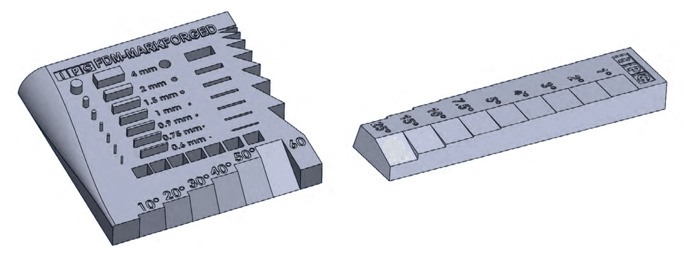
Benchmark geometries.
2. Material characterization, design, and 3D printing guidelines
3. Injection trials: IPC executed two tests with different sets of molds. In the first trial, they used a test design and injected almost a hundred of polypropylene parts using a mono-material mold printed in Formlabs High Temp Resin. In the second trial, they used a more challenging test design but this time injected thousands of polypropylene parts with a multi-material mold, core and inserts printed with Formlabs Rigid 10K Resin and the frame printed in PA12 with SLS.
Mold Design
Parts and Molds Description
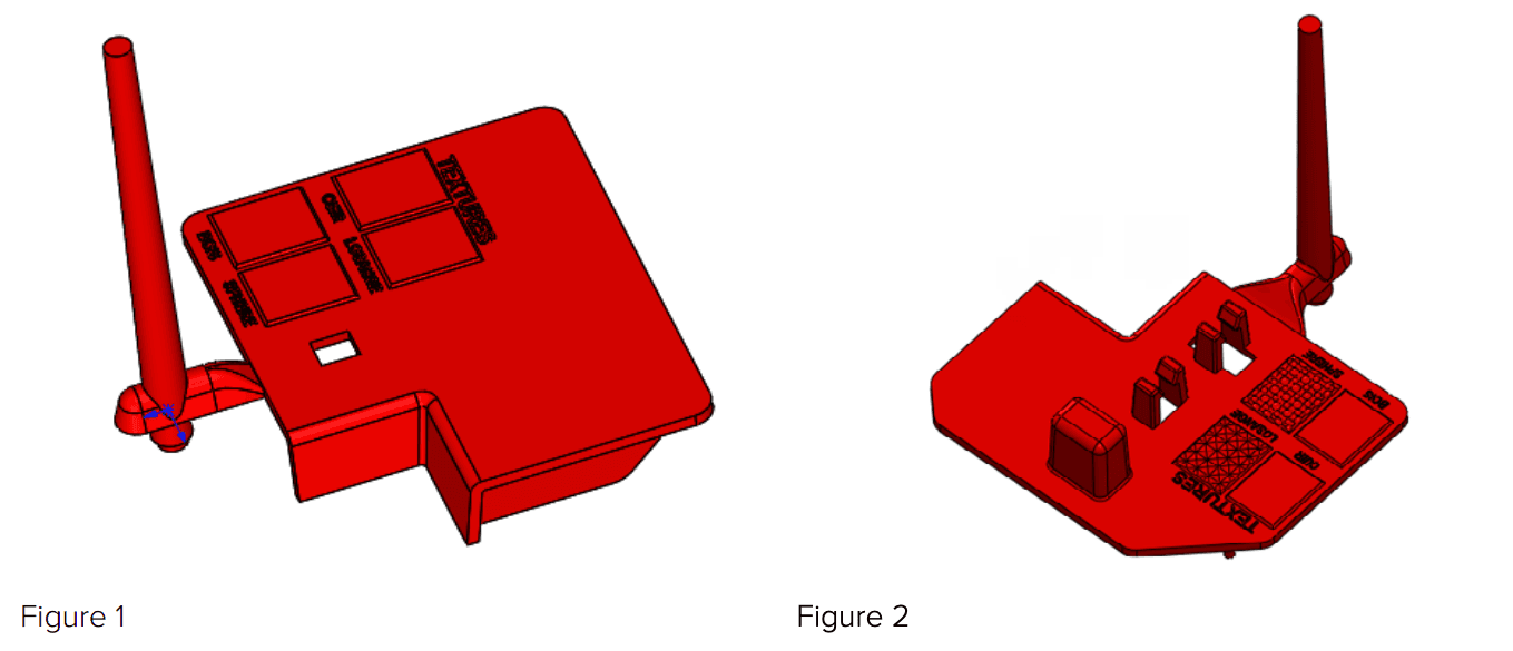
CAD design of the two final parts: first test part molded with a mono-material mold without inserts (Figure 1) and second toture part molded with a multi-material mold with inserts (Figure 2).
IPC designed two mold sets to inject two different challenging parts. For both sets, they intended to optimize the quality of the parting line: both halves of the tool must be positioned within a tolerance of ±0.02mm in order to obtain a good fit.
1. A mono-material mold printed in High Temp Resin. It carries a simple geometry without insert or side action, and includes texturing. The parting line will be reworked in a finishing step to improve the parting line.
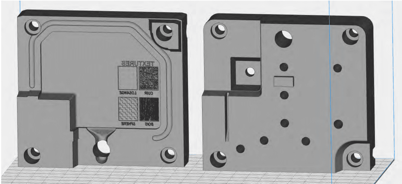
STL file of the mono-material mold printed with High Temp Resin, loaded in the PreForm print preparation software. Stationary side (left) and moving side (right).
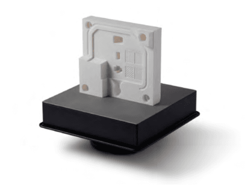
2. A multi-material mold: The stationary side of the mold is printed with Rigid 10K Resin and includes texturing. The moving side is made of one core and four inserts printed in Rigid 10K Resin and a frame printed in PA12 with selective laser sintering (SLS) technology. The soft frame is designed with a pad to compensate for the dimensional variation from the parting line. PA12 is flexible enough to absorb the dimensional dispersion during mold clamping. However, SLS should be used only to print the frame and not the whole mold because it does not provide a fine enough resolution for the molding surfaces and melts at high temperature.
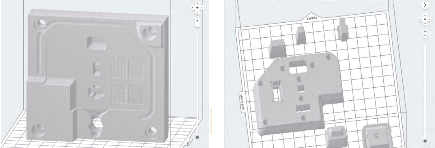
STL files of the multi-material mold loaded in the PreForm print preparation software: stationary side (left) and moving side core and inserts (right) printed with Rigid 10K Resin.
This geometry is a little more challenging in order to test the resistance of inserts with low thickness. There is a three degrees draft angle between the core and the frame to facilitate assembly. The frame was built with a 0.05 mm stock allowance to allow a better fit.
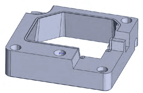
CAD design of the PA12 frame for the moving side of the multi-material mold.
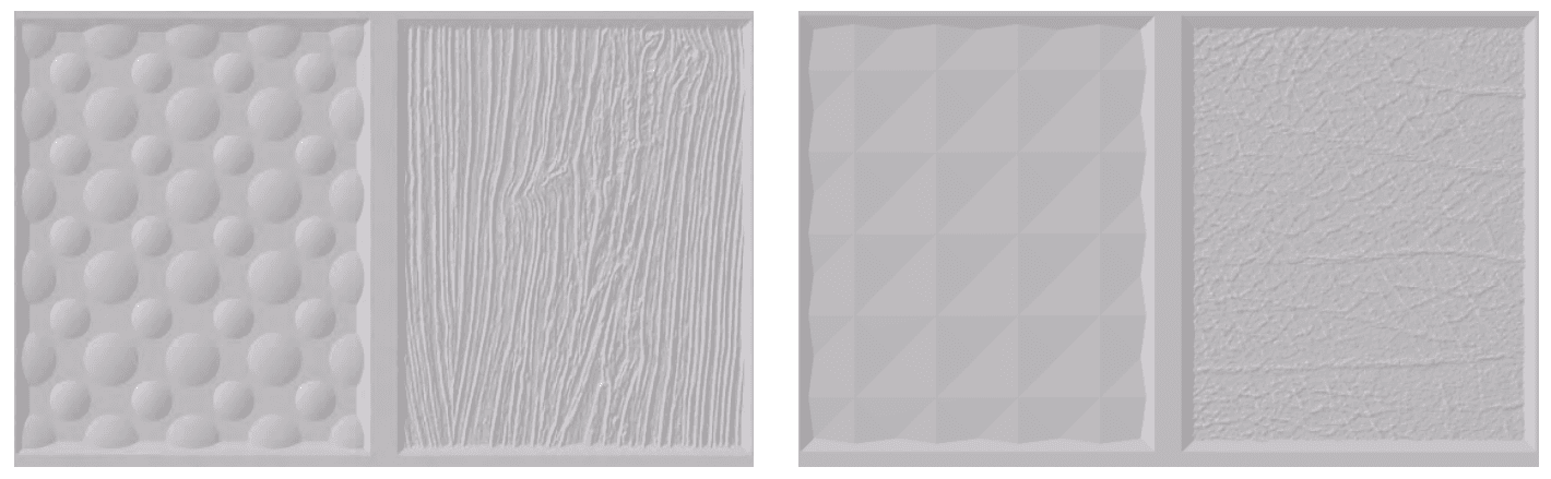
CAD file of the molds, view of the textures similar for both tool sets. From left to right: (1) Large sphere 1.82 mm radius and 0.3 mm height. Small sphere 1.09 mm radius and 0.3 mm height. (2) Wood: 0.25mm height. (3) Pyramid: 0.3 mm side and 0.2 mm depth. (4) Leather: 0.14 mm height.
Design Guidelines
IPC ran a few design iterations and recommends the following best practices:
- Plan stock allowance on the printed mold and machine it to adjust dimensions.
- Avoid small section cores: parts with the section smaller than the height might not resist the pressure and temperature. IPC advises printing multiple inserts for thin overhanging parts— they can be replaced in case of failure—or fabricating the small pieces in metal.
- Design with measures larger than 400 mm might be challenging. Because dimensional variation increases with the size, it will be more difficult to achieve a mold fit. • Increase draft and overhang angles (10° to 20°) to avoid deformation.
- Not to integrate cooling channels in the mold design. Because thermal transfer occurs slower in plastic parts than metal parts, cooling channels would not have enough impact on the temperature to justify the time spent for designing this system. Regulation might be beneficial in the case of challenging design or materials, but this needs to be researched further.
Mold 3D Printing
3D Printing Resin
The molds were 3D printed with the Form 3 3D printer and post-treated with Form Wash and Form Cure stations. The first tool was printed with High Temp Resin at 25 microns layer height. The second mold set was made of a frame printed with SLS technology in PA12, and a core printed with Rigid 10K Resin at 50 micron layer height.
Mold printed with Rigid 10K Resin, stationary side on the build platform.
3D Printing Guidelines
After a few iterations, IPC recommends the following 3D printing best practices:
- Print with Rigid 10K Resin to increase mold longevity.
- Use a small layer height for a better resolution: SLA printing enables very fine texturing.
- When possible, print the mold flat without supports to obtain better dimensional accuracy and avoid warping.
- Orient the mold in order to reduce overhanging parts.
- When possible, print both halves aligned in reference to the build direction. Potential size
variations will be more consistent and improve the quality of the parting line. - Finish the 3D printed mold with machining. In particular, adjust the parting line to fit both halves of the mold together and avoid flashing. Diameters tend to deform and drilling holes might be necessary.
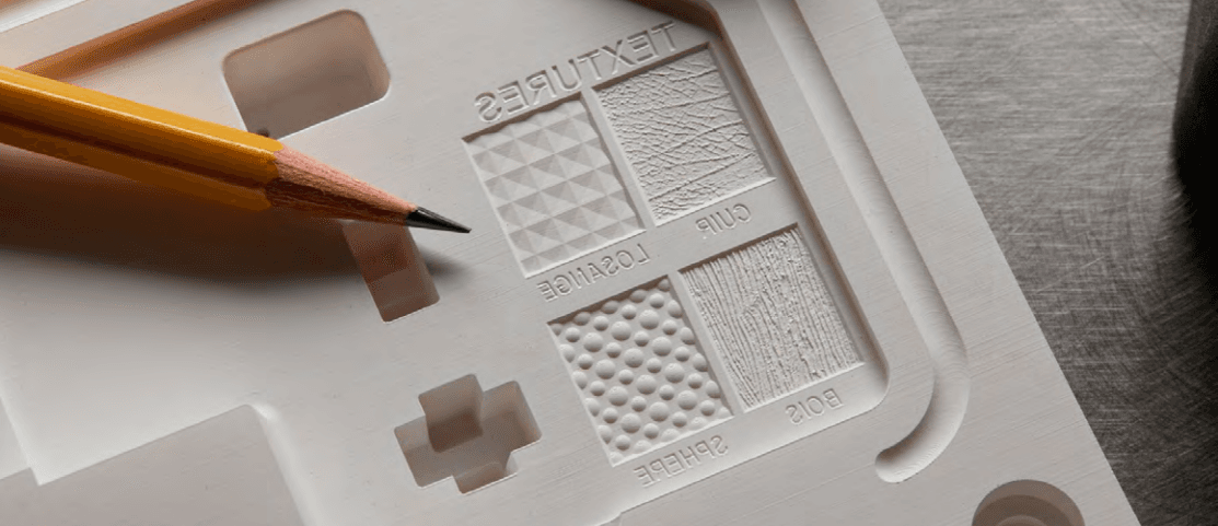
Textures printed on the Rigid 10K Resin mold.
Scanning Metrology
IPC scanned the printed molds to measure the dimensional variation, right after printing and postcure. These scans show a variation smaller than ±0.05 mm for more than 75% of the part.
HIGH TEMP RESIN
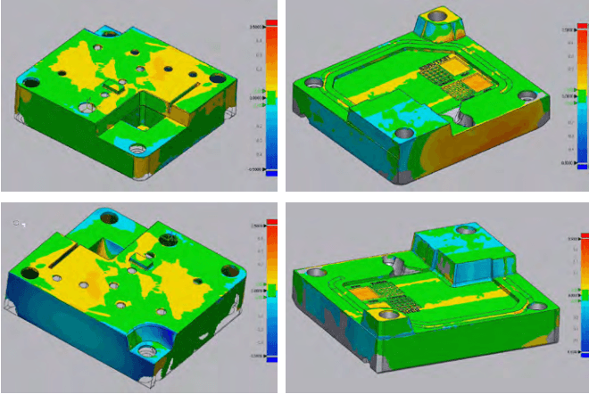
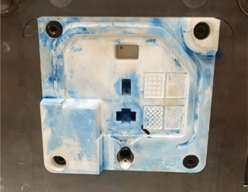
Scans of the mold 3D printed with High Temp Resin: dynamic side (left) and stationary side (right).
RIGID 10K RESIN
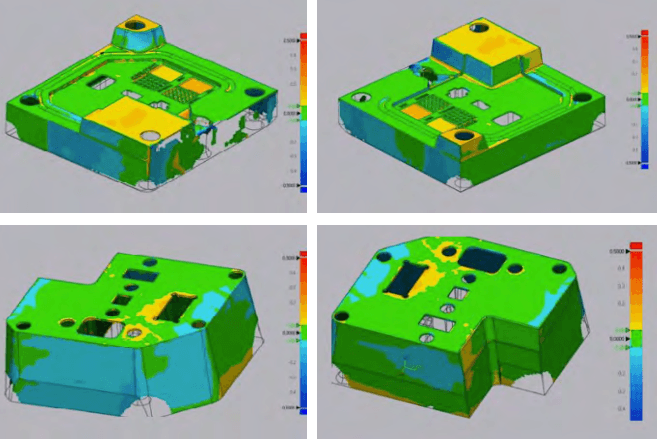
Scans of the mold 3D printed with Rigid 10K Resin: dynamic side (left) and stationary side (right).
Injection
Mold Assembly
As mentioned above, it is recommended to machine the 3D printed mold before assembly in order to meet critical dimensions. However, the multi-material mold did not need to be machined, as the soft parting line in PA 12 could absorb the dimensional variations. Ejector pins or inserts can then be added. IPC advises to print multiple inserts for thin overhanging parts showing more risk of breakage: they could easily be replaced in case of failure. Mold machining and assembly are sensitive operations to execute with care as the 3D printed parts could break during treatment. The 3D printed molds should be placed inside a metal die or mold master in order to support against the pressure.
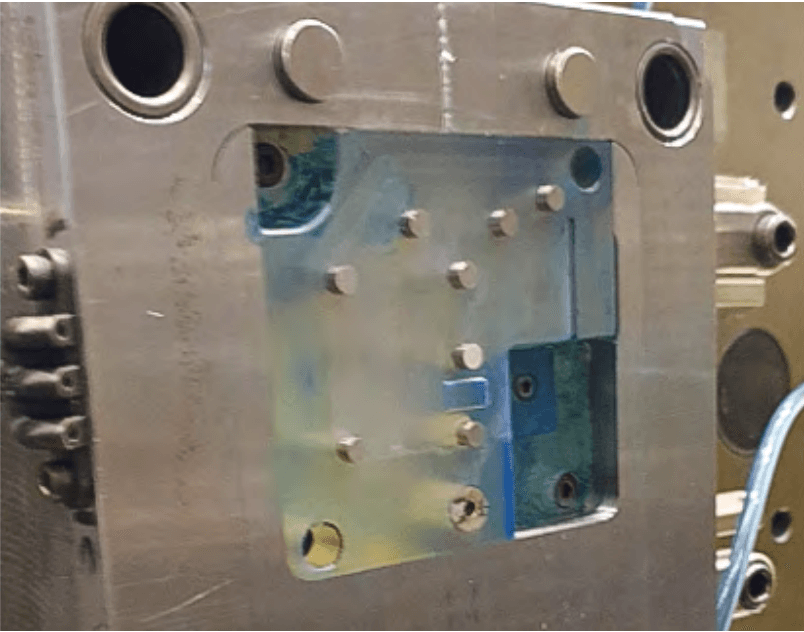
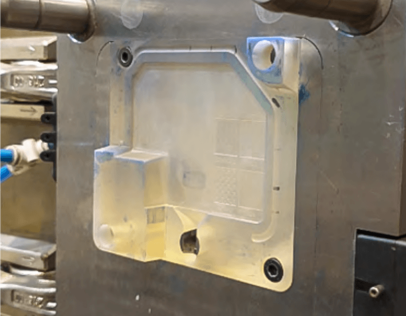
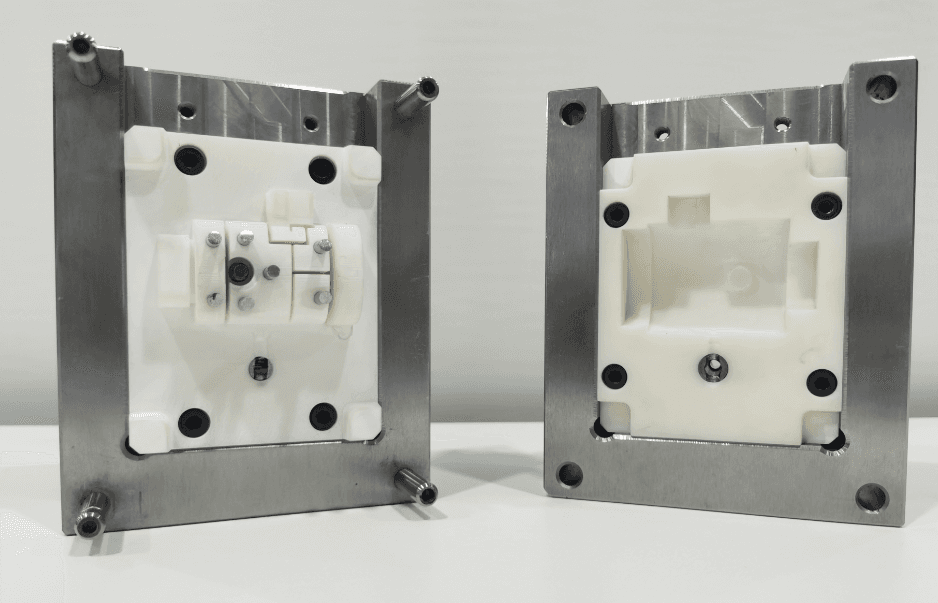
Mold printed with High Temp Resin assembled in the metal die. Moving side with ejector pins (left) and stationary side (right).
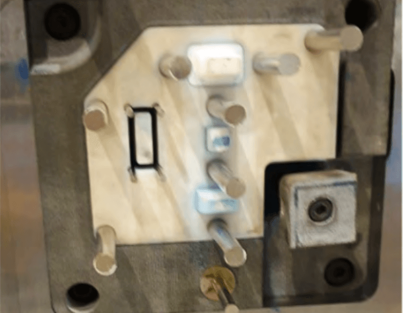
Mold printed with Rigid 10K Resin assembled in the metal die. Moving side with ejector pins, inserts, SLS frame (left) and stationary side (right).
Molding Process Conditions
The team injected thousands of parts under the following molding conditions:
- Injection molding machine: industrial, ENGEL 150T
- Injected material: polypropylene (PP)
- Injected temperature: 200 °C
- Injected pressure: 180 Bars
- Clamping force: 125 KN
- Release agent: none
- Cooling system: none. The temperature was controlled with a thermographic camera and the cycle started only when the temperature of the printed mold was below 36 °C.
- Ejection: automatic with ejector pins and robotic arm to move the part
- Cycle time: 150 sec
Results
IPC injected 90 polypropylene parts with the mono-material mold printed in High Temp Resin.
The parts injected showed high-quality surface finish and level of details. However, the mold started cracking after 31 iterations, which impacted the surface quality of the remaining molded parts.
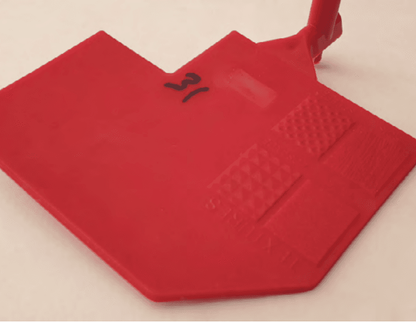
Part number 31 (left) part number 90 (right) injected with High Temp Resin mold.
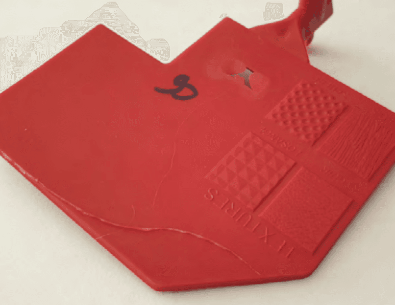
High Temp Resin mold after 90 injections.
IPC injected 1000 polypropylene parts with the multi-material mold printed in Rigid 10K Resin. The parts injected showed high-quality surface finish and level of details. They observed light flash from the first injections and small cracks around the core clips after 900 injections. A brightness appeared at the gate location as well.
Light flash on the final part (left) and small cracks after 900 injections on the Rigid 10K Resin core.
Textures on the final parts injected with the multi-material mold.
IPC recommends choosing Rigid 10K Resin in order to increase mold longevity, it is less brittle and shows better strength under stress than the High Temp Resin. The 3D printed mold should be machined in order to improve the accuracy of the parting line and reduce flashing. Alternatively, using a multi-material mold with a soft frame is a great solution to compensate for dimensional variations. IPC expects the injection process to be more challenging with viscous materials such as polycarbonate (PC) and injection temperatures over 240 °C.
Conclusion
IPC evaluated the usability of 3D printed molds for low-volume injection molding. With a mold core printed in Formlabs Rigid 10K Resin, and a soft frame printed in PA12, they could inject thousands of parts with polypropylene, reducing cost by 80-90% compared to a metal mold.
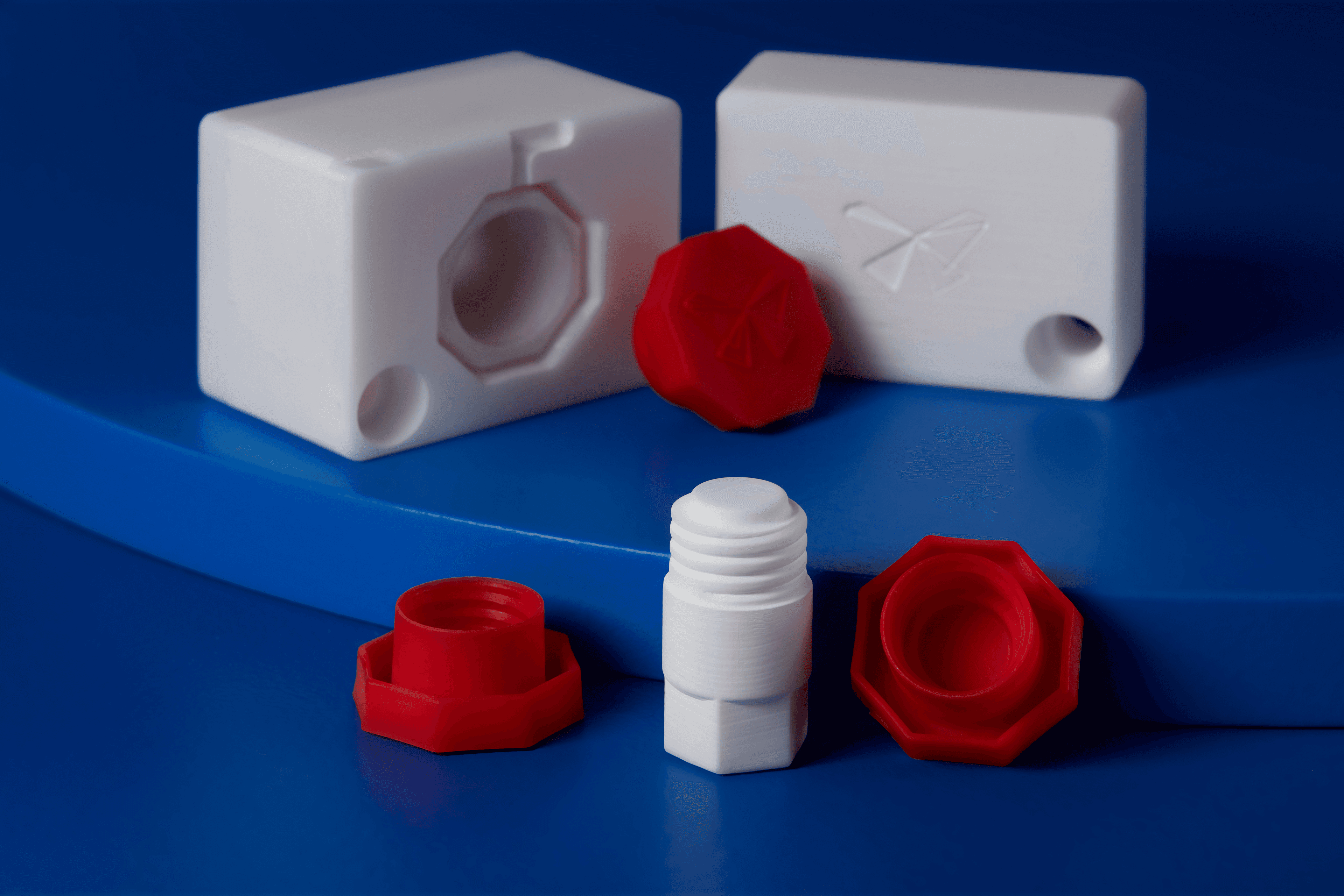
Novus Applications Injection Molded Hundreds of Threaded Caps With a Rigid 10K Resin Three-Part Mold
This case study showcases how the high stiffness and temperature resistance of Rigid 10K Resin allows intricate mold geometry, including a threaded side-action core.
Background and Challenge
Novus Applications is a product development company focusing on consumer goods. Experienced in injection molding and 3D printing, they run design for manufacturing and moldability studies for their customers. Speed is crucial for the team as they need to quickly deliver low-volume series of prototypes. They conducted an internal study to test the viability of using a 3D printed mold in the injection molding process to fabricate a small batch of caps. They were specifically looking at the dimensional stability and longevity of the printed molds; how the molds would behave under the heat and pressure of the process and how many injection cycles they could expect from one mold.
Design Process
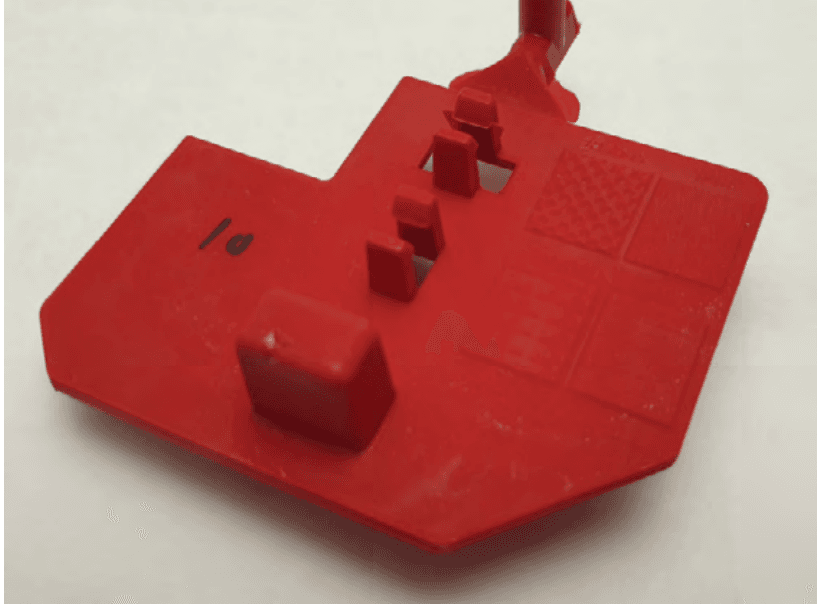
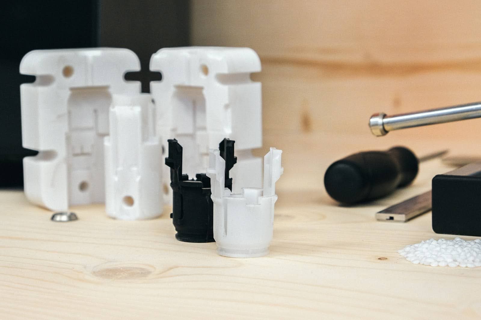
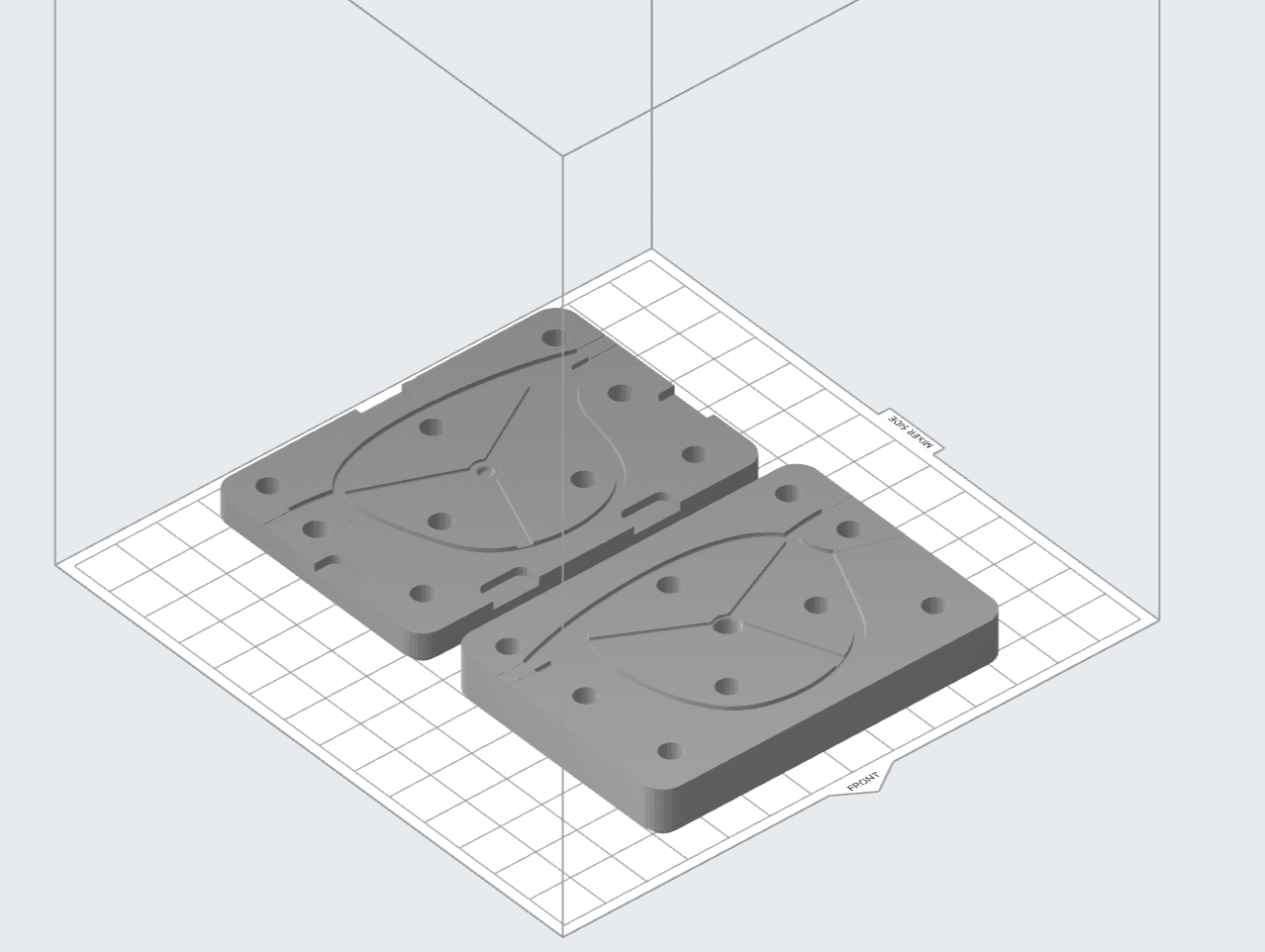
Mark Bartlett, the founder and president of Novus Applications, wanted his team to create a generic cap with an internal thread that was applicable for both tubes and bottles. It requires a complex, three-part stack with a dynamic threaded core. Bartlett followed the usual recommendations for designing a mold for injection molding. Specifically, he included draft angles to facilitate the demolding process, supported all free-hanging cores where possible, and avoided very thin cross-sections. In an effort to reduce the pressure in the cavity, he drew large gates and incorporated venting to get the gas out of the mold. Finally, some extra material was planned to groom the blocks in a post-processing step.
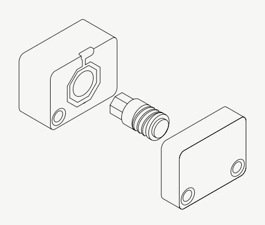
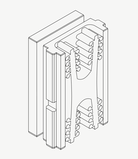
This is a three-part mold with a moving B side cavity (left), a threaded side-action core (middle) and a stationary A side (right).
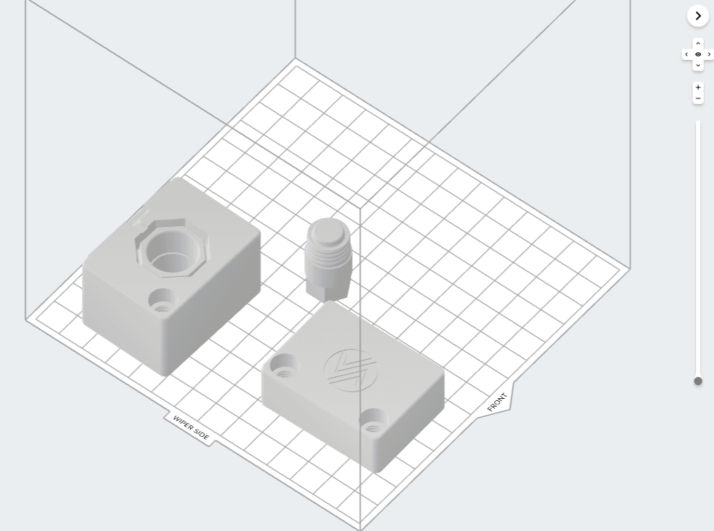
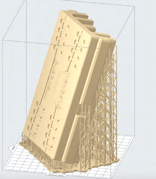
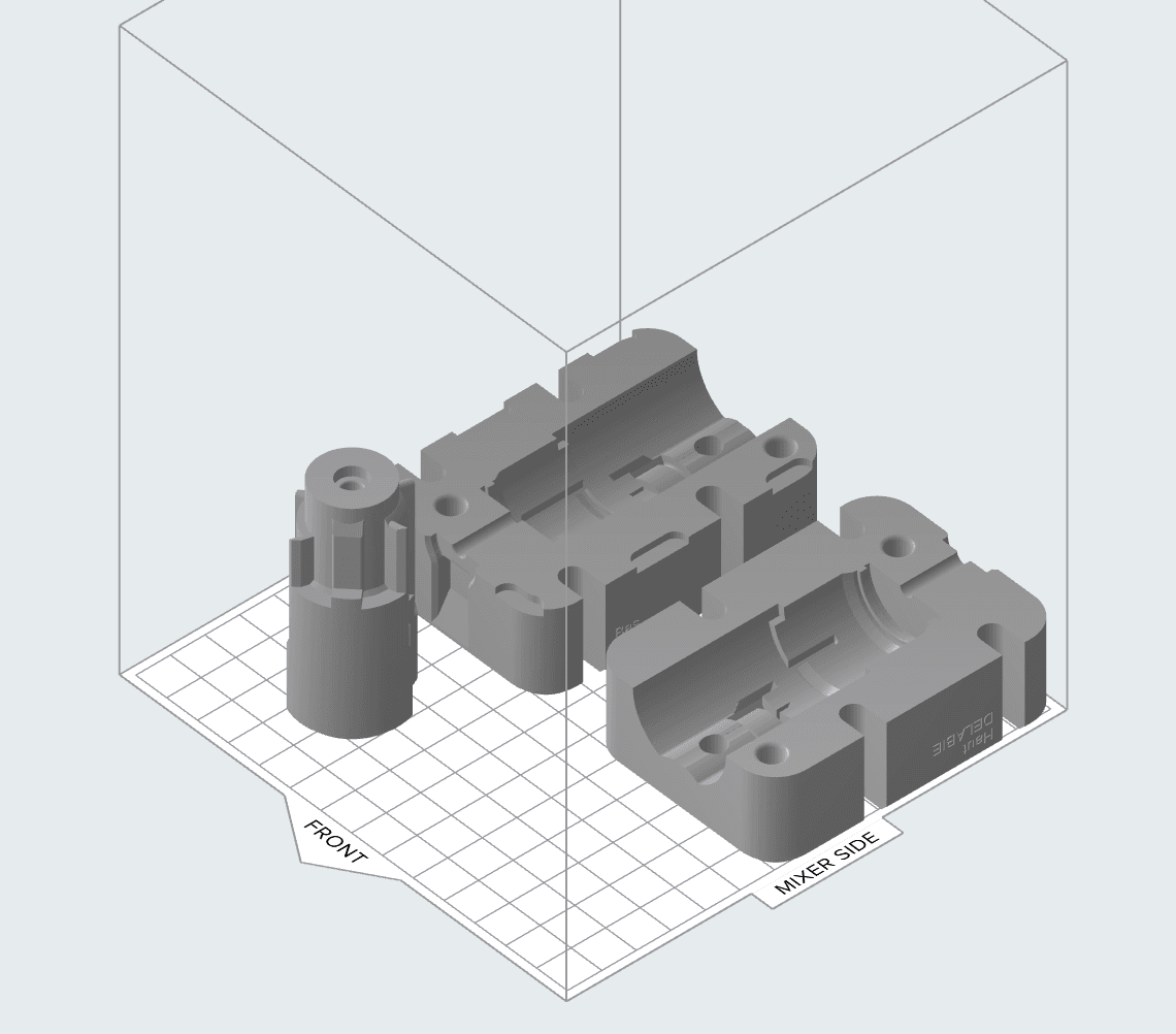
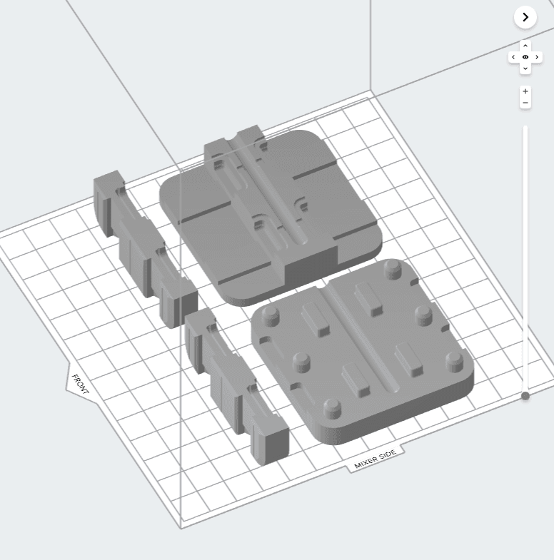
The CAD file of the mold loaded into Formlabs PreForm software for print preparation.
3D Printing Process
Bartlett was looking for a 3D printing material stiff enough to withstand the pressure of the process while being able to render the fine details of the design. Having used FDM printing technology before, Bartlett knew that his project required the higher resolution that SLA technology can offer. He opted for Formlabs Rigid 10K Resin as it is an extremely stiff material with high tensile strength and tensile modulus, and great dimensional stability. High Temp Resin was also considered but did not perform as well, he needed the mechanical properties that Rigid 10K Resin offers rather than the thermal properties of High Temp Resin.
The molds were printed overnight on the Form 3 printer with Rigid 10K Resin at 50-micron layer height. They printed extra side-action cores in case of failure during the demolding. They were subsequently washed in IPA twice for 10 minutes and post-cured. It is recommended to post-cure Rigid 10K Resin parts in Form Cure for 60 minutes at 70 °C, and then heat the part at 90 °C for 125 minutes for a higher HDT. The parts were then post-processed to match the desired sizes. Bartlett designed the molds with additional stock allowances in mind so that the mold's key surfaces and features could be fine-tuned in post-processing operations, allowing him to achieve a perfect fit inside the press. Common post-processing operations include drilling out or reaming holes and sanding or milling faces to achieve the tight tolerances necessary to reduce print defects.
Molding Process
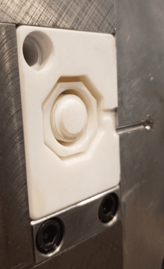
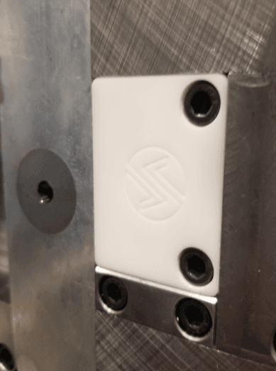
The printed molds were placed into a metallic frame before injection. The side-action core went inside the B side (left) which was clamped to the stationary A side (right).
The team operated an all-electric Sumitomo 50-ton press. The printed molds were placed into a prefabricated metallic mold frame inside the machine. They injected three different materials; a low melt PP (P5M6K-048 Red), high melt PP (PP1013H1 White), and high melt PE (Marlex 9018 HDPE). PP is quite easy to process and does not require very high pressure. The table below shows the injection conditions used for one printed mold.
|
Injected Material |
P5M6K-048 Red |
PP1013H1 White |
Marlex 9018 HDPE |
|
Melt Index |
35 |
7.5 |
20 |
|
Nozzle Temperature |
390 °F (199 °C) |
410 °F (210 °C) |
400 °F (204 °C) |
|
Injected Pressure |
6,800 psi |
9,500 psi |
7,200 psi |
|
Cycle Time |
48 sec |
50 sec |
68 sec |
|
Number of Injection Cycles |
30 |
30 |
30 |
|
Pressure to Failure |
Not tested |
11,500 psi |
Not tested |
Cycle times were slower than in a traditional injection molding process, including the injection, cooling, and manual demolding. The injection speed was reduced in order to keep the pressure low. To shorten the cooling time of the plastic mold, Bartlett printed multiple cores and was not running consecutively on the same core in order to leave the ones cooling on the side. There were no water cooling channels available but the aluminum frame could absorb some part of the heat. The demolding process is a sensitive step as the mold can be damaged during the operation. The team was ejecting and unscrewing the part from the side-action core manually, and had to pay attention to not break the core during the separation. They first applied a release agent to facilitate it, but it turned out not to be necessary as the draft angles were sufficient. They did not notice any chemical reaction between the printed resin and the injected materials.
Results
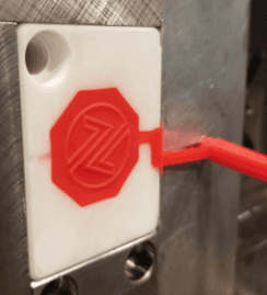
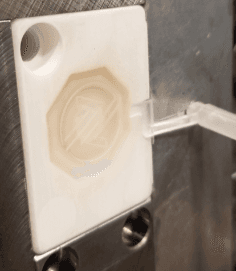
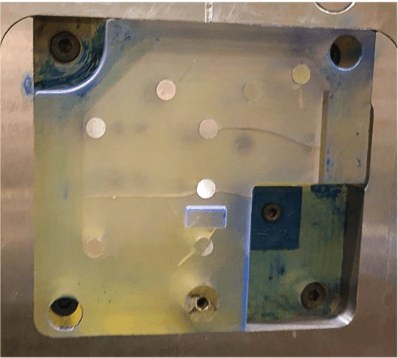
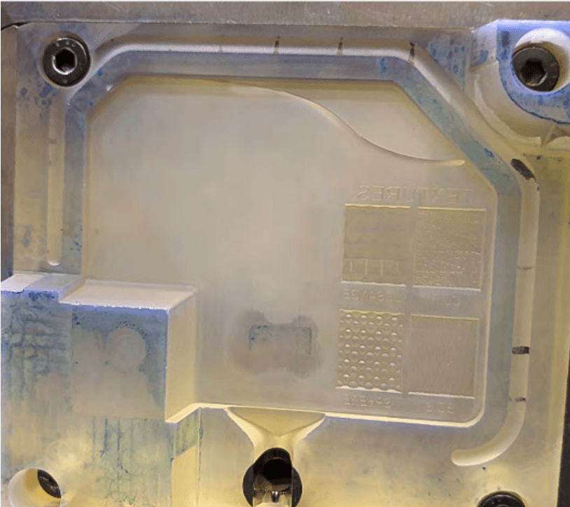
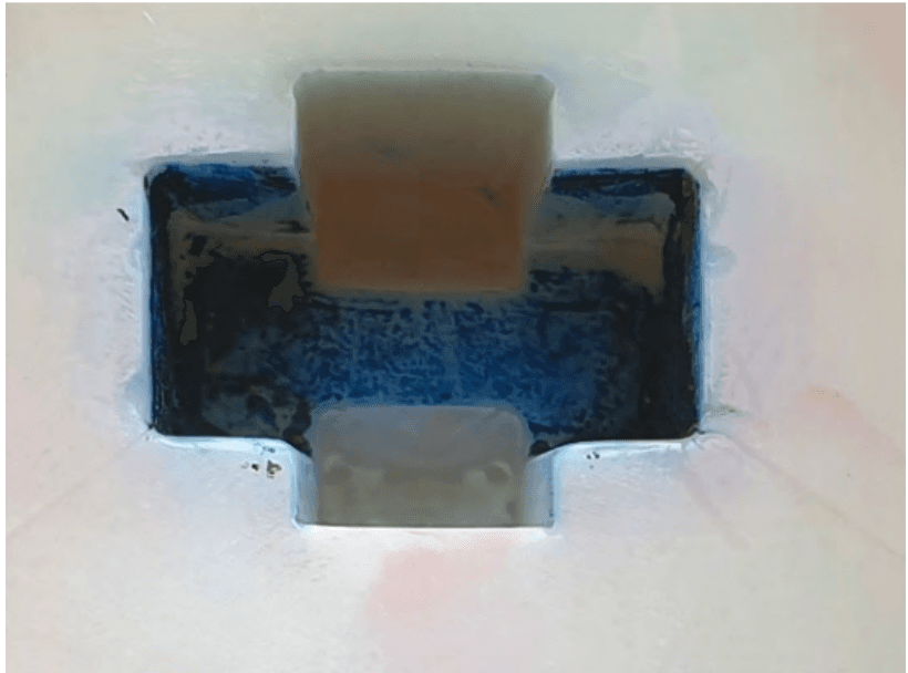
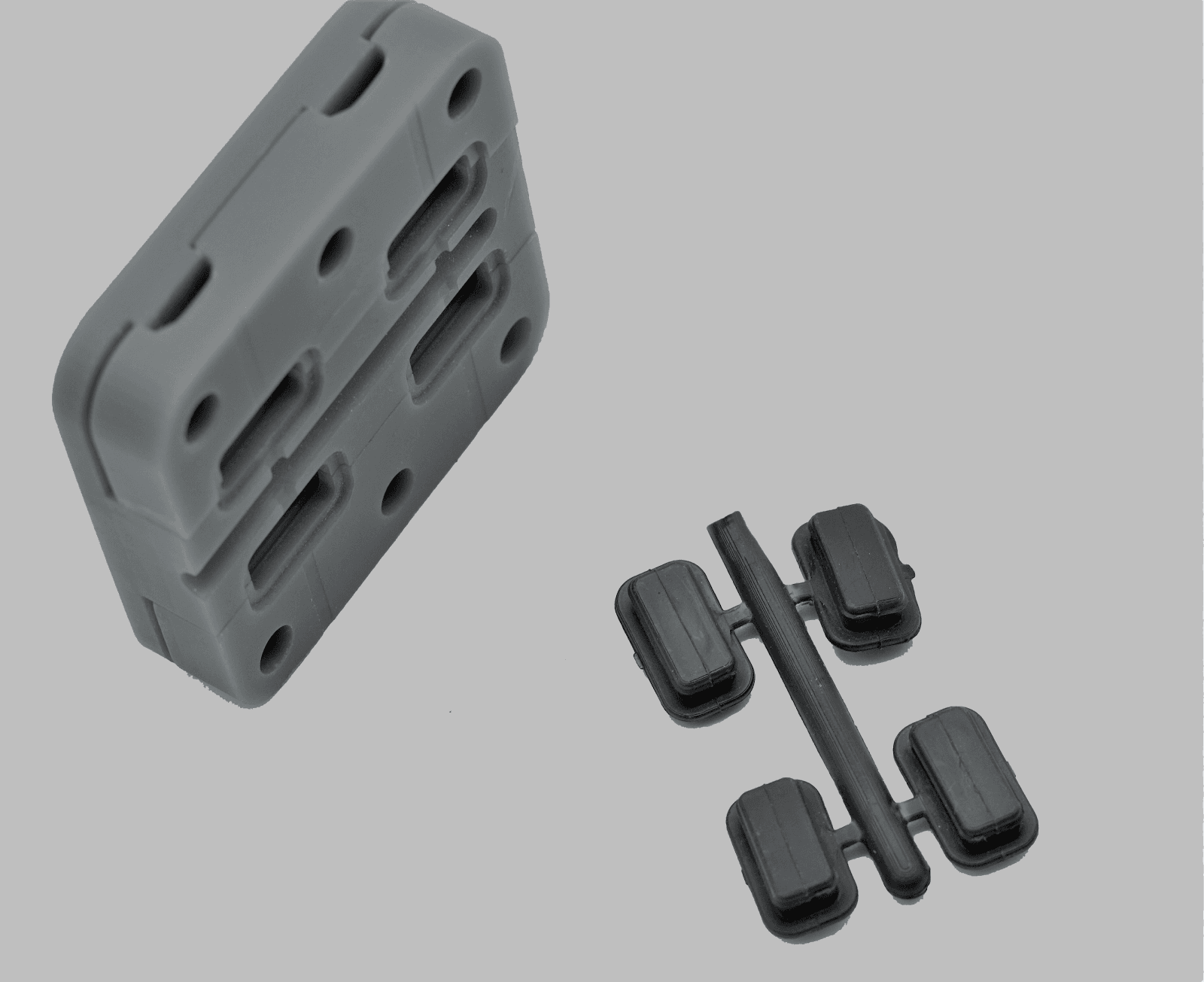
The mold cavity after the injection of P5M6K-048 Red (left) and PP1013H1 White (right) materials.
With maintaining the injection pressure under 11,500 psi, the team operated about a hundred injection cycles for one mold. The lead time of this project was about two days, from idea to production. The team drew the mold in a few hours, printed it overnight, and needed half a day to prepare and assemble the mold and another half a day to mold the parts. They used only one CAD model, however, more complicated parts would require a few more days for design iterations.
The next table displays measurements of the final part injected in three different materials. For each, the team measured 20 diameters of the inside of the threaded cap to assess the repeatability of this process. We can observe an average deviation from the mean diameter of ±0.04 mm over these 60 caps, reflecting good dimensional stability.
|
Material |
P5M6K-048 Red |
PP1013H1 White |
Marlex 9018 HDPE |
|||
|
Mean |
0.515 in |
13.072mm |
0.520 in |
13.207 mm |
0.517 in |
13.134 mm |
|
Cycle Number |
Deviation (in) |
Deviation (mm) |
Deviation (in) |
Deviation (mm) |
Deviation (in) |
Deviation (mm) |
|
1 |
0.000 |
0.009 |
0.002 |
0.052 |
0.000 |
-0.003 |
|
2 |
0.002 |
0.060 |
0.001 |
0.027 |
0.002 |
0.048 |
|
3 |
0.001 |
0.034 |
0.000 |
0.001 |
-0.002 |
-0.053 |
|
4 |
0.005 |
0.136 |
0.001 |
0.027 |
0.004 |
0.099 |
|
5 |
0.000 |
0.009 |
-0.001 |
-0.024 |
0.003 |
0.074 |
|
6 |
-0.001 |
-0.017 |
-0.001 |
-0.024 |
0.000 |
-0.003 |
|
7 |
-0.001 |
-0.017 |
-0.004 |
-0.100 |
-0.001 |
-0.028 |
|
8 |
-0.002 |
-0.042 |
0.002 |
0.052 |
-0.001 |
-0.028 |
|
9 |
-0.002 |
-0.042 |
-0.002 |
-0.050 |
0.000 |
-0.003 |
|
10 |
0.000 |
0.009 |
-0.003 |
-0.075 |
0.001 |
0.023 |
|
11 |
0.000 |
0.009 |
0.004 |
0.103 |
-0.001 |
-0.028 |
|
12 |
-0.003 |
-0.067 |
0.001 |
0.027 |
-0.001 |
-0.028 |
|
13 |
0.000 |
0.009 |
-0.001 |
-0.024 |
0.002 |
0.048 |
|
14 |
-0.002 |
-0.042 |
-0.001 |
-0.024 |
0.002 |
0.048 |
|
15 |
0.003 |
0.085 |
0.003 |
0.077 |
-0.002 |
-0.053 |
|
16 |
0.000 |
0.009 |
0.002 |
0.052 |
-0.001 |
-0.028 |
|
17 |
-0.002 |
-0.042 |
-0.002 |
-0.050 |
-0.002 |
-0.053 |
|
18 |
-0.003 |
-0.067 |
-0.003 |
-0.075 |
0.001 |
0.023 |
|
19 |
0.000 |
0.009 |
0.002 |
0.052 |
0.000 |
-0.003 |
|
20 |
-0.002 |
-0.042 |
-0.001 |
-0.024 |
-0.002 |
-0.053 |
|
Average From Absolute Deviation |
0.001 |
0.038 |
0.002 |
0.047 |
0.001 |
0.036 |
Costs Analysis
"If my customer only needs 20 parts why would I need an aluminum mold? With 3D printing technology, the team shows a much faster learning curve, the production is more unattended — specifically thanks to the Form 3’s ease-of-use."
With this workflow, Novus Application saved a lot of time and simplified a previously complex process. Normally, they would have machined the mold in-house out of a block of steel or aluminum, which would be far more labor-intensive. It would take a few more days and require high-end software with highly trained operators. Due to the more expensive equipment and materials, both machine time and the production cost of the mold would have been substantially higher. For this project, Bartlett estimates that 3D printing the mold cost less than half of machining it in house.
“It always depends on the part that you are working on — I can print complex parts accurately way faster than I am going to machine them,” said Bartlett.
|
In-House Machined Metal Mold |
In-House 3D Printed Mold |
|
|
Equipment |
CNC machine and software Injection molding machine PP, HDPE |
Form 3 printer Rigid 10K Resin Injection molding machine PP, HDPE |
|
Mold Production Time |
Two days |
One day |
|
Mold Production Cost |
2x |
<1x |
Braskem Fabricated Thousands of End-Use Mask Straps in a Week
This case is an example of a very simple insert geometry, flat with no fine features, where reducing cooling time was critical to producing thousands of polypropylene (PP) parts in a short time.
Background and Challenge
Being one of the world’s leading petrochemical companies, Braskem is well experienced in injection molding. Michelle Sing, Jake Fallon, Collins Azinger, and Fabio Lamon work on exploring opportunities with additive manufacturing for Braskem’s customers. One particular interest is to help their community gain access to temporary tools and gain flexibility in production with rapid tooling. The urgent need for masks during the COVID-19 crisis led them to test the viability of using a 3D printed mold with injection molding. They needed to design and produce thousands of mask straps within a week to distribute to Braskem employees. After initially considering directly 3D printing the straps with FDM printers and machining a traditional mold out of tooling metal, they ultimately landed on 3D printed injection molds to reduce costs and turnaround time.
Design Process
Fallon went through three design iterations with this insert in order to increase the number of cycles before breakage, lessen flashing to shorten demolding time, and save resin. Here is an overview of the modifications:
|
Mold V1 |
Mold V2 |
Mold V3 |
|
|
Design Features |
Added draft angles |
Added draft angles Enlarged gate |
Added draft angles Enlarged gate Added large vents (against flashing) Reduced the cross-section in some areas |
|
Results |
500 cycles |
1,500 cycles |
2,500 cycles Alleviated flashing 28% in resin savings |
The one-side mold directly locked to a metallic plaque.
The final CAD file of mold loaded into Formlabs PreForm print preparation software. The part was printed tilted with supports. Smaller molds can also be printed directly on the build platform to minimize post processing time.
3D Printing Process
The team printed on the Form 3 with High Temp Resin. Thanks to the Form 3’s Remote Printing feature, Fallon could work on the CAD file from home and start the print remotely, so that the part would be printed by the time he arrived back in the office in the morning. He opted for a 50-micron layer height in order to balance the time to print while obtaining a good surface finish and help demolding. This resin was chosen because of its high HDT which could handle an average molding temperature of 230 °C with a short cooling time. Formlabs Rigid 10K Resin could also bear this temperature for such a short exposure. It took about 24 hours to build the part. They were subsequently washed in IPA for six minutes, post-cured for 120 minutes at 80 °C, thermally post-cured for three hours at 160 °C, and then hand sanded to fit inside the system.
Molding Process
The team operated an all-electric press Cincinnati Milacron 110 Ton Roboshot. Braskem was using a one-sided printed insert, slid into the system, and directly locked to a metallic plaque, which helped to hold at high pressure. They injected generic polypropylene (PP), which has good flexibility and toughness. They chose a higher melt flow PP for low viscosity in order to minimize the injection pressure, extend the lifetime of the mold, and avoid flashing. To minimize the injection pressure they kept the temperature in the barrel higher to reduce the viscosity of the melted plastic. Some of the molding conditions were: five-ton clamping pressure, 20-second cycle time, injection speed of 0.5 in/s, and hold pressure of 5,000 psi for about eight seconds.
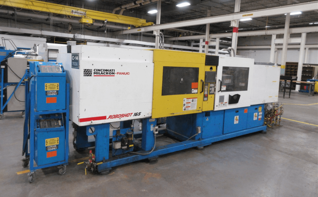
Cincinnati Milacron Roboshot.
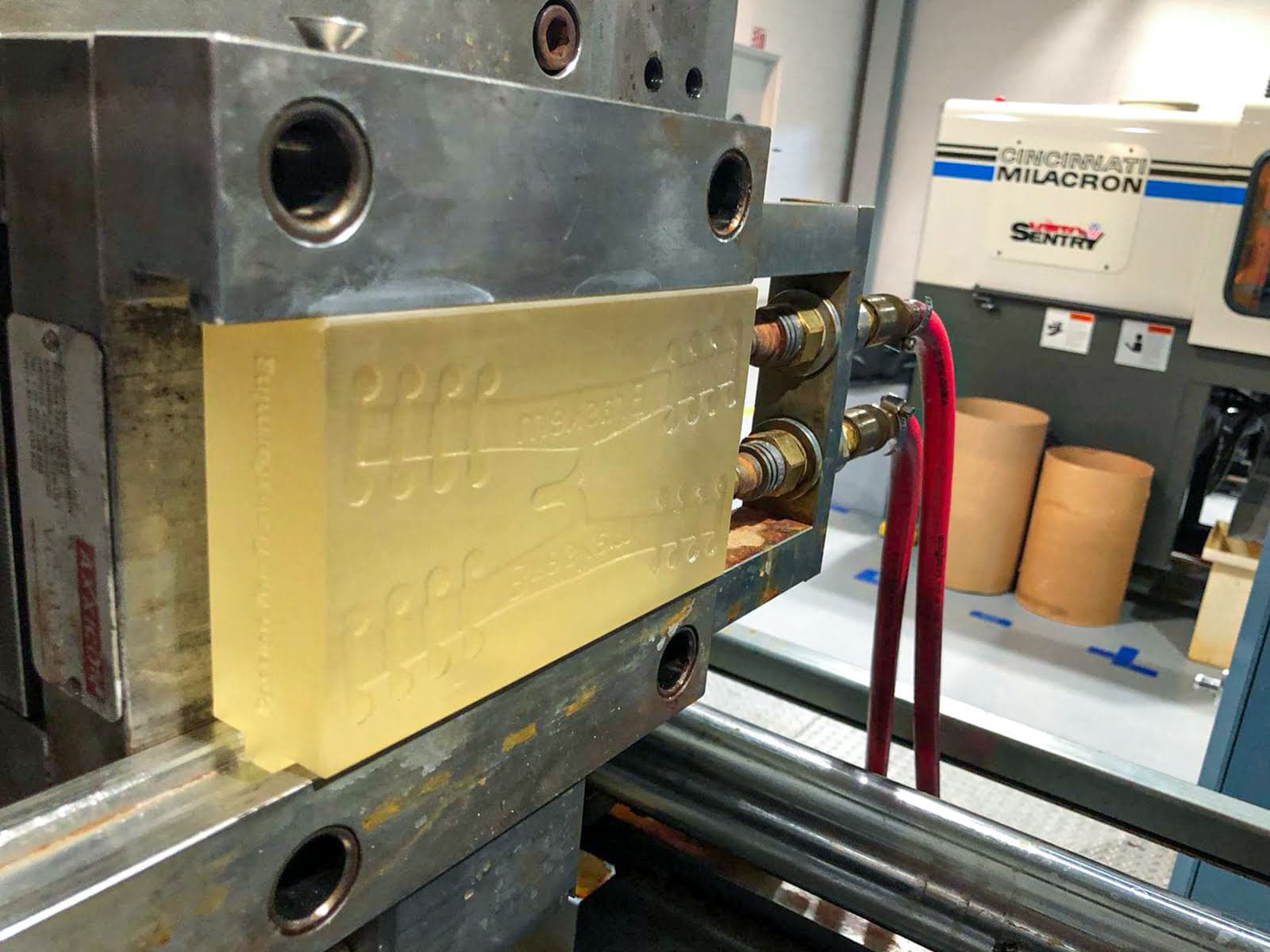
The printed mold insert (V1) slid into the injection molding machine.
The demolding process was quite labor-intensive. The team trimmed the gate and purged the vents manually. They applied MR303 silicone food grade release agent from Sprayon to facilitate the separation, spraying after every 50 to 60 shots. There were no ejection pins or cooling system. However, they managed to reach an average total cycle time of 30 seconds, including cooling and manual separation.
Results
The team ran between 1,500 and 2,500 injection cycles with one printed mold before breakage. Producing four straps per minute, they used two molds for the total production, and more than 8,000 mask straps were distributed to Braskem team members in the USA, Mexico, and Brazil. The high number of cycles is largely the result of the structural simplicity of this insert — flat with a large gate, no intricate features, and held inside a metallic frame. For this project, Braskem went from idea to production within a week.
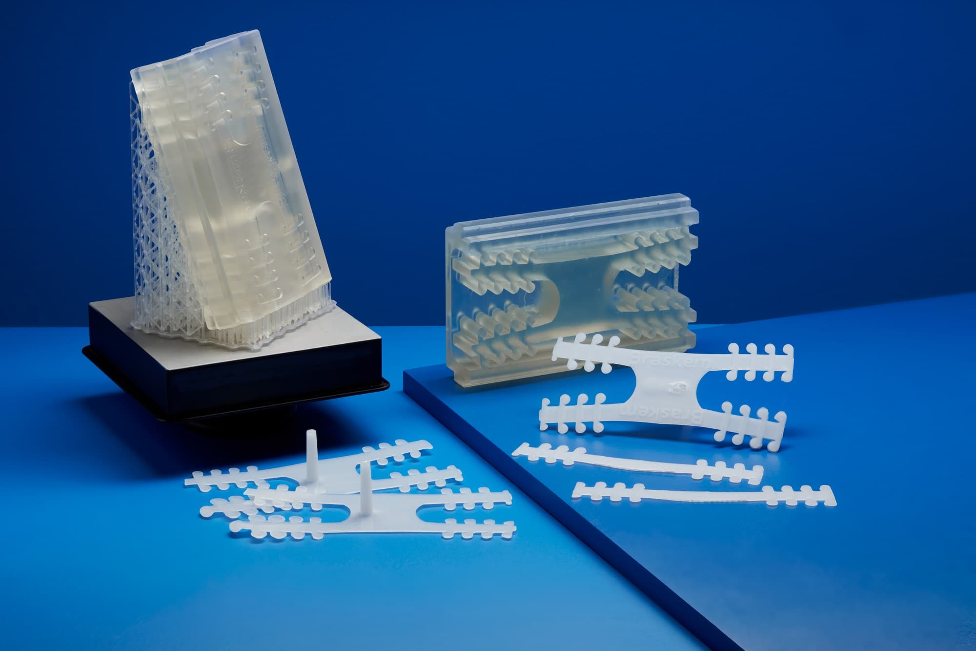
The mold insert printed with High Temp Resin next to the two straps injected in polypropylene.
Costs Analysis
Braskem considered three possibilities to produce these masks. Given that they only had a week to deliver the masks, reducing the overall project time was a crucial requirement. Therefore they included the mold fabrication time and costs when comparing each method. By choosing injection molding with an in-house 3D printed mold, Braskem obtained 90-94% time saving and 80-97% cost savings compared to the alternatives.
|
In-House Direct 3D Printing |
Injection Molding With Outsourced Metallic Mold |
Injection Molding With In-House 3D Printed Mold |
|
|
Equipment |
FDM printer |
Injection molding machine, PP |
Form 3 printer, High Temp Resin, Injection molding machine, PP |
|
Mold Production Time |
Zero |
30 days |
One day |
|
Mold Production Costs |
Zero |
$10,000-15,000 |
$200 |
|
Total Project Time (including mold fabrication and 8,000 straps production) |
72 days (13 minutes/strap) |
32 days |
Three days |
|
Total Project Costs (including mold fabrication and 8,000 straps production) |
$2,080 |
$10,160-$15,160 |
$360 |
Holimaker Produces Hundreds of Prototypes and Pre-Production Parts With a Desktop Injection Molding Ecosystem
Using a desktop injection molding machine is a great way to leverage this process with limited investment and maintenance for prototyping or to test the workflow before committing to industrial equipment. This case shows how to get started with injection molding low volumes of small parts using different resins.
Background and Challenge
French startup Holimaker wants to make plastic manufacturing accessible by fabricating micro-industry tools for plastic processing. Their core product, the Holipress, is a manual injection molding machine that enables engineers and product designers to process plastic on their desktop in low quantities for prototypes, pilot production, or even limited series of end-use parts.
The company offers feasibility studies to their customers, using 3D printed molds for their fast turnaround and low costs. This allows their clients to quickly and affordably prototype designs and validate final manufacturing conditions during the pilot production phase of new product introduction. By using the same manufacturing method, including mold design and materials, these parts can be tested in the field and ensure the designs are ready to be produced at scale. The 3D printed mold designs can then be easily adapted for tool-grade steel during mass production.
Holimaker uses 3D printed molds in 80% to 90% of their current project. We met with Managing Director Aurélien Stoky and Marketing Director Vivien Salamone to understand how they combine both technologies.
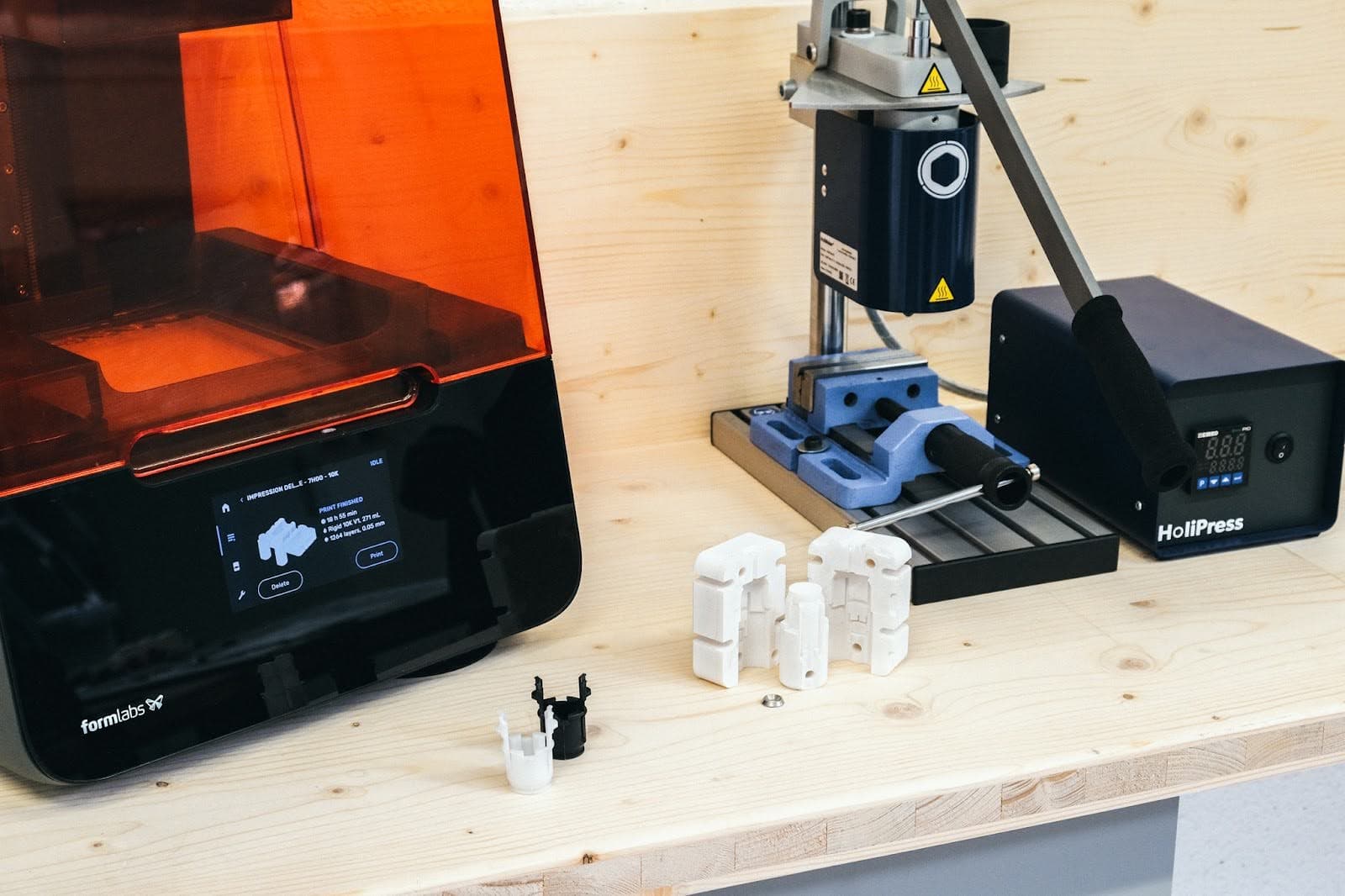
The Holipress, a Form 3+ printer, and molds printed in Rigid 10K Resin.
"The blocker in injection molding is to manufacture the mold. In order to democratize injection molding and make it accessible to everyone, we had to find a complementary technology to produce our mold. Desktop printing was a perfect fit for this. We combine the flexibility of 3D printing with the productivity and quality of injection-molded plastic," Stoky and Salamone said.
Holimaker has looked into alternative ways for mold making. For orders over a thousand parts, they would employ a machined aluminum mold, but for smaller quantities, they run the press on 3D printed molds. In some cases they combine both in a similar way as Braskem: for large volumes with demanding geometries, they machine the outside of the mold and 3D print the insert, which is replaced over time.
Design Process
Usually, the team iterates on three to four models per project in order to optimize the design. They follow the general molding recommendations, such as including draft angles. They mostly work on small parts, and add 0.1 mm vents and 0.5 mm runners.
In addition, they respect a few printing rules such as including chamfers to help to remove the piece from the build platform, some centering pins to align both prints, and notches to assist opening with a screwdriver. They usually use 10 mm thick molds and avoid thin cross-sections. Parts that are only 1-2 mm thick cannot endure the high temperatures.
3D Printing Process
Holimaker’s team prints the molds directly on the build platform at a 50-micron layer height. For small parts, this orientation saves printing time and resin by not using support structures; the team also observed better dimensional accuracy on the mold surfaces after curing. If dimensional errors occur, it is usually on the outside of the block that they post-process with hand sanding to fit the frames.
Holimaker prints with both Rigid 10K Resin and Grey Pro Resin. Grey Pro Resin is a more affordable resin suitable for molding a few units of small parts at low pressure. However, molds printed with Grey Pro Resin may deform as the number of cycles increases, therefore they favor Rigid 10K Resin for more technical projects.
Molding Process
The team uses the Holipress injection molding machine in all their studies. It is a small manual press, easy to use, and available at a tenth of the cost of an industrial press. The molds are placed into a prefabricated aluminum frame which holds the pressure better and ensures that the injection nozzle is not in direct contact with the printed mold.
With Formlabs printed molds, Holimaker injects a broad range of thermoplastics with different levels of hardness from Shore 40A to 90A, at a three to five minutes cycle time. The number of cycles per mold varies from about 10 parts for a PA injected at 270 °C to hundreds of parts for a PP, TPE, or POM injected at lower temperatures. Holimaker is developing an integrated cooling system to help reduce the cooling time before demolding.
Results
The team chose SLA 3D printing from Formlabs for its part quality and ease of use. "The quality of our injected parts is very good because of the high-quality molds. And when I start a print in the evening, I am almost sure to have a good mold ready the following day," they said.
Stoky and Salamone had used another desktop printing technology before, but observed too much deformation on the prints even prior to injection.
Holimaker produced prototypes of a valve connector part for a customer to carry out resistance tests to water pressure. The part injection molded in POM using 3D printed molds withstood 25 bars of pressure, while the same part machined in POM only withstood eight bars of pressure.
“Formlabs parts offer great dimensional accuracy and surface finish. If there is a dimensional error, it is very minor, and it is uniform on the three axes, therefore we can predict it and post-process it. With other desktop printers, we could not control the deformation," said Stoky.
The team also appreciates the simple workflow that is easy to learn and operate, for example, automating the washing and curing process with Form Wash and Form Cure. They can go from design to molded parts within a working day and then also iterate the design to optimize the model. "We often design the mold in the morning, print it during the day and we can test the injection in the afternoon to modify the CAD model and start a second print overnight," said Stoky.
Holimaker shared a few cases from their customers to give a better understanding of the part, molding conditions, and results of their feasibility studies.
| Company |
Valves and Fittings Manufacturer |
FERME 3D | Eyewear Manufacturer |
| Product | Valve connector | Face shield clip | Eyewear frame |
| Need | To be able to quickly prototype a valve connector part in order to carry out resistance tests to water pressure. | Test a solution to produce a series of 10,000s of parts in a short time. | Test compatibility of eyewear materials with printed molds to produce a series of 200 frames. |
| Mold Material | Rigid 10K Resin | Grey Pro Resin | Grey Pro Resin |
| Materials Injected | POM (190 °C) / PA6 15% GF (280 °C) / PP (210 °C) | PP (food-grade, 220 °C) | ASA (240 °C), PA (240 °C) |
| Number of Parts for One Mold | 12+ | 100 | 70 |
| Cycle Time | Five minutes | Two minutes | Two minutes |
| Project Lead Time | Two weeks | One week | Two weeks |
Costs Analysis
|
Outsource Machined Metal Mold |
In-House 3D Printed Mold |
|
|
Equipment |
Holipress, thermoplastics |
Holipress, thermoplastics, Form 3+ printer, Grey Pro Resin or Rigid 10K Resin |
|
Mold Production Time |
Three to five weeks |
One week |
|
Mold Production Costs |
4-5X |
1X |
Valves and Fittings Manufacturer: Mold CAD and Injected Part
FERME 3D: Mold CAD and Injected Part
Eyewear Manufacturer: Mold CAD and Injected Part
Conclusion
The conversation around 3D printing and injection molding is often oppositional, but it’s not always a question of one versus the other. By directly 3D printing rapid prototypes and parts, and using 3D printed injection molds for later-stage functional prototyping with end-use materials, product validation, and low-volume production, your company can leverage the benefits of both technologies. This will make your manufacturing process more time- and cost-efficient and allow you to bring products to the market faster.
The cost and lead time of producing parts in limited volume can often be a barrier to introducing a new product. With this hybrid process, it is possible to shorten the time from concept to production while delivering a series of parts in traditional thermoplastics and even manufacture custom or limited series of end-use parts. With SLA 3D printing, you can now make it all happen affordably, within a few days.
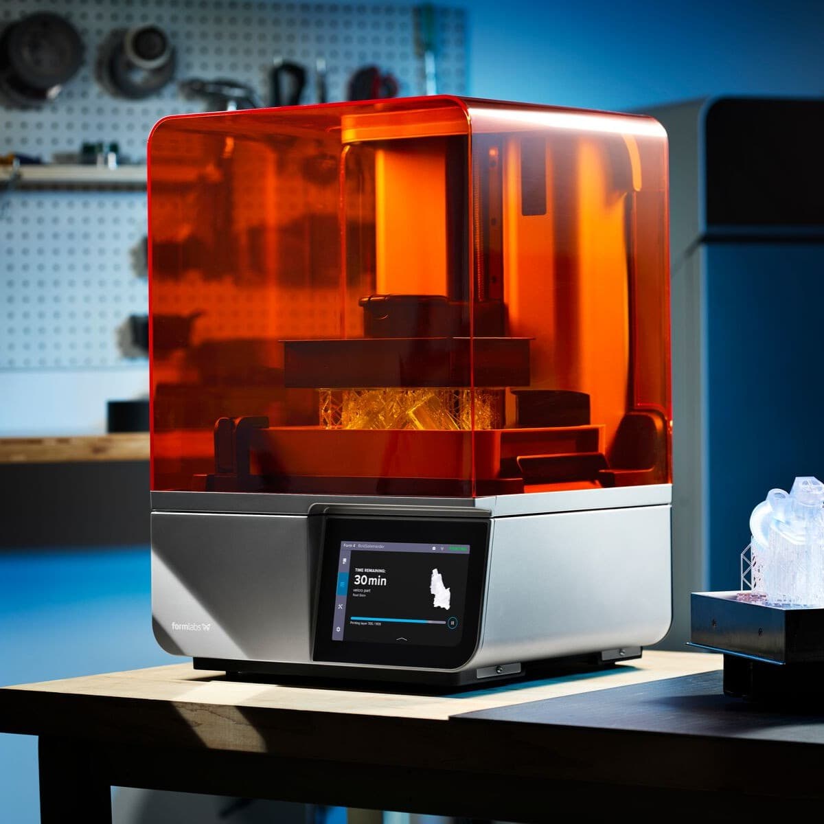
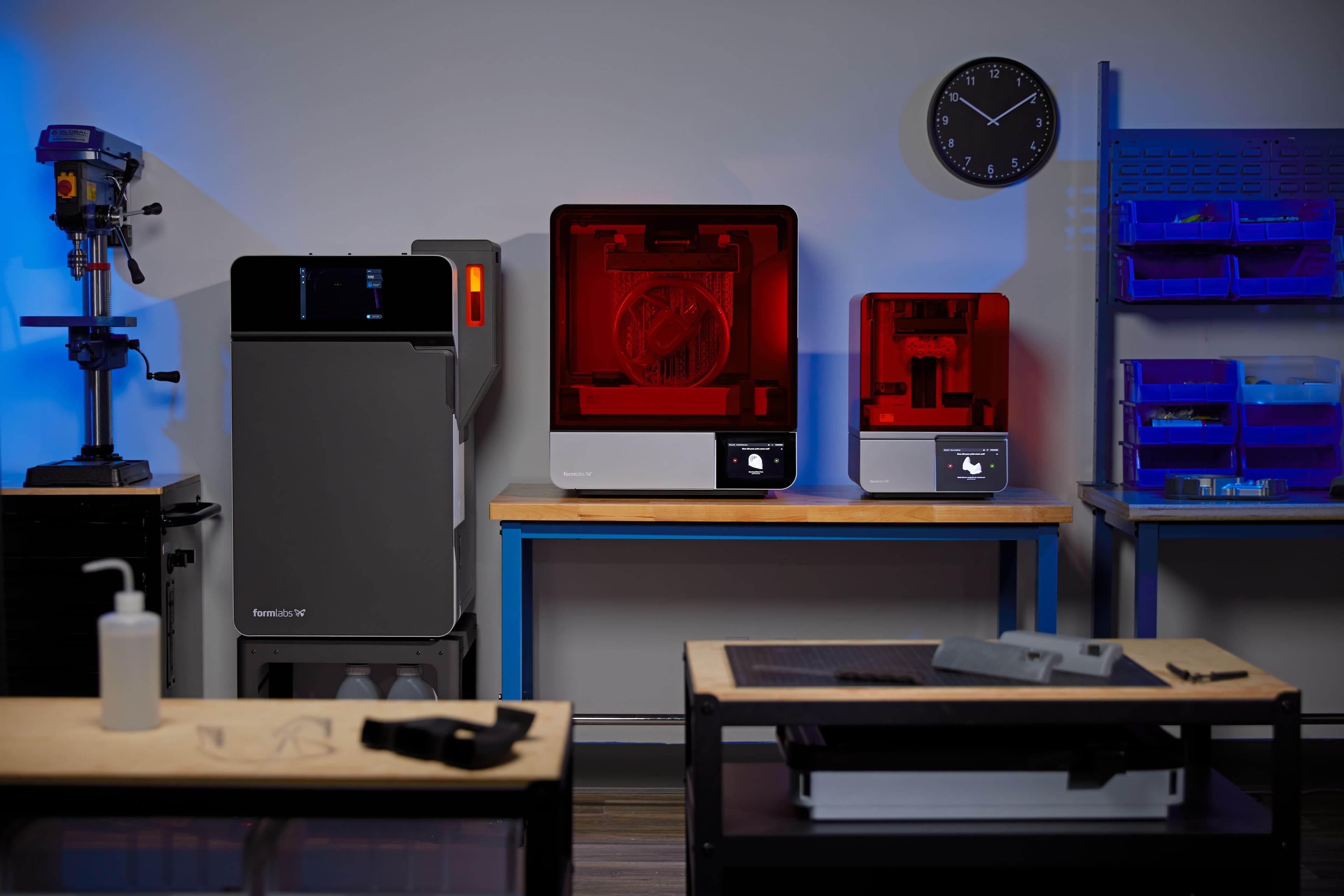
Whether you are looking for a desktop solution or something to implement on the factory floor, Formlabs’ complete, easy-to-use 3D printing ecosystem can seamlessly be integrated into any injection molding workflow. The Form 4 is ideal for 3D printing injection molds and with the Form 4L, Formlabs’ large format SLA 3D printer, you can scale this process to large molds and tackle even more applications. Users are also exploring techniques such as electroplating or assembling multi-material printed stacks to expand the capabilities of short-run molds.
Do you have questions about using an SLA printer for injection molding or other engineering and manufacturing applications? Reach out to our solutions specialists or request a free sample of one of the three materials showcased in this white paper.
Request a free sample part to see Formlabs 3D printed materials firsthand and contact our 3D printing specialist to find the right solution for your application.