placeholder
WHITE PAPER

Creating Bone-Simulation Models for Cutting and Drilling

3D printed bone-simulation models are revolutionizing medical training, surgical planning, research, and medical device development by putting realistic, patient-specific replicas of skeletal structures in the hands of healthcare professionals, researchers, and engineers. The in-house production of bone-simulation models offers a number of advantages over traditional methods that use cadaver bones or generic outsourced models: decreased costs, shortened wait times, and the opportunity to create custom or patient-specific geometries.

This application guide walks through the bone-simulation material options for stereolithography (SLA) 3D printing and the entire in-house manufacturing process for bonelike anatomical models intended for cutting and drilling.

Creating Bone-Simulation Models for Cutting and Drilling

placeholder

3D printed bone-simulation models are revolutionizing medical training, surgical planning, research, and medical device development by putting realistic, patient-specific replicas of skeletal structures in the hands of healthcare professionals, researchers, and engineers. The in-house production of bone-simulation models offers a number of advantages over traditional methods that use cadaver bones or generic outsourced models: decreased costs, shortened wait times, and the opportunity to create custom or patient-specific geometries.

This application guide walks through the bone-simulation material options for stereolithography (SLA) 3D printing and the entire in-house manufacturing process for bonelike anatomical models intended for cutting and drilling.

What Is a Bone-Simulation Model?

Bone-simulation models are functional anatomical models that exhibit mechanical properties similar to real bone when cut or drilled. These models are often used in medical education settings for surgical practice and training. Sometimes, these models are created based on patient scans to model the anatomy associated with a specific surgical case. In these cases, the models are used by clinicians to practice a particular approach prior to the real operation, and may even be sterilized to go into the operating room (OR) with the surgeon. In other cases, bone-simulation models may be used by medical device developers to test the fit and function of bone-interfacing tools, such as cutting guides and templates.

bone model

Spine model printed in Rigid 4000 Resin and cured without heat.

Determining Bone-Simulation Materials

To determine the most bone-like materials from our extensive material offerings, we collected detailed feedback from eight clinical collaborators, and some of their colleagues, with extensive bone-cutting/ drilling experience. Each collaborator was provided with a series of bone models that were based on their own patients’ scans and printed in a series of different materials. The collaborators performed standard procedures on these models including cutting and drilling with bone drills, saws, and reamers. Qualitative feedback was collected via video call, and quantitative feedback was collected via a scoring matrix that encompassed a series of bone-like qualities. Recommended materials were determined based on overall performance score and these results were supported by qualitative feedback.

Choosing the Right Material

Our primary material recommendation for creating bone-simulation models is BioMed Durable Resin. BioMed Durable Resin is a clear material developed for biocompatible applications requiring impact, shatter, and abrasion resistance. Despite being transparent, BioMed Durable Resin ranked the highest in mechanical performance similar to bone. Some testers even said that they preferred the material’s transparency over standard opaque bone models because it enabled better visualization of the procedure being practiced. The radiopacity of BioMed Durable Resin is approximately 84 HU, which is lower than most types of bone but still visible by CT. Parts printed with BioMed Durable Resin can be sterilized, and are therefore suitable for use in the OR for surgical planning purposes.

Our secondary recommendation for bone-simulation models is Rigid 4000 Resin cured without heat (CWH). Rigid 4000 Resin did not score quite as high as BioMed Durable Resin on mechanical likeness to bone, but was still a frontrunner. This material was particularly appealing to testers who wanted models to be opaque. Curing without heat allows the user to differentiate the mechanical properties on the outside of the model from the inside of the model, in an attempt to better simulate the mechanical differences between spongy bone and compact bone. The radiopacity of Rigid 4000 Resin is 341 HU, loosely within the range for cancellous bone.

More information on the procedure used to determine these radiopacity values can be found here.

  BIOMED DURABLE RESIN RIGID 4000 RESIN
Mechanical Performance ★★★★★ ★★★☆☆
Visual Likeness to Bone ☆☆☆☆☆ ★★★★☆
Radiopacity Likeness to Bone ★★☆☆☆ ★★★★☆
Biocompatible
Sterilizable


bone models

Bone-simulation anatomical models printed in Rigid 4000 Resin cured without heat (left) and BioMed Durable Resin (right).

"Formlabs BioMed Durable is my preferred resin for creating bone-like models. The clear nature of this material is what I find most useful in clinical cases, allowing all vital anatomic landmarks to be easily identified in preparation for surgery. In my practice, BioMed Durable is also used for teaching/training, giving novices full visibility of important structures to be encountered during procedures."

- Desmond Tan,

BVSc (Hons), DACVS-SA, Alfred Veterinary Orthopedics

“BioMed Durable strikes the perfect match between the little flexibility that thinner bones provide with realistic fractures under pressure. Combined with the ease of printability, this material is a great fit for medical simulation.”

- Dr. Lauren Schlegel,

MD, Beth Israel Deaconess Medical Center

Designing and Printing Bone-Simulation Models

What’s Required?

FROM FORMLABS:

WARNING:

For biocompatible applications, separate accessories (dedicated resin tank, build platform, and finishing equipment) must be maintained to comply with biocompatibility standards. Resin Washing Solution is not compatible with biocompatible resins.

FROM THIRD PARTIES:

  • IPA (99% or higher) for washing parts

1. Design

1.1 Scan

Start with a CT, MRI, or 3D ultrasound image of the bony anatomy of interest.

The quality of this image is most often the limiting factor in printed part resolution. When imaging using CT, MRI, or 3D ultrasound, you may want to consider these scanning modalities and slice thickness recommendations from Boston Children’s Hospital, as well as these considerations from the Radiology Society of North America (RSNA) Special Interest Group for 3D Printing. Users are encouraged to check with their segmentation software provider for more specific recommendations.

Prior to imaging, it should be confirmed that both the tool and imaging personnel have up-to-date accreditations, and that images have been acquired within a reasonable amount of time to still accurately represent the patient’s anatomy and pathology.

1.2 Segment

Accuracy errors are most likely to be introduced during the medical image segmentation phase. If segmentation is part of your workflow, extra precautions should be taken to ensure that you are reconstructing anatomy with the highest accuracy possible and meeting the clinical requirements defined by the physician.

The healthcare professional handling segmentation must be cautious of any possible image distortions and address them in this stage. Automated segmentation and any 3D surface mesh reconstruction should be carefully reviewed, ideally by a radiologist. The accuracy of the segmented model can be verified before printing by overlaying surface contours onto the original medical images.

Segmentation software packages should adhere to internal Quality Management Systems (QMS) and regulatory standards. Validation, such as IQ/OQ/PQ evaluations, should be conducted regularly on the segmentation software. Formlabs has several preferred segmentation partners, including Materialise. Materialise offers a great how-to video on the segmentation and preparation of bony anatomy for 3D printing using the Mimics Innovation Suite.

materialise mimics innovation

Segmentation of bony anatomy based on a patient scan using the Materialise Mimics Innovation Suite.

1.3 Optimize for Printing

Some bone models may require additional modification in order to print successfully. In some cases, you may need to hollow, add holes for drainage, or thicken weaker areas. Make sure that the finished model adheres to Formlabs’ design guidelines for Form 4 Series printers, Form 3/3B, or Form 3L/3BL. Some edits to your model can be made in PreForm, but most should be made in your segmentation software or CAD software of choice.

2. Print

2.1 Import File

Check that your version of PreForm is up to date by going to Help, then Check For Updates in the upper left-hand corner. Import or open your part file by dragging it into PreForm, or by going to File, and then Open, in the upper right-hand corner.
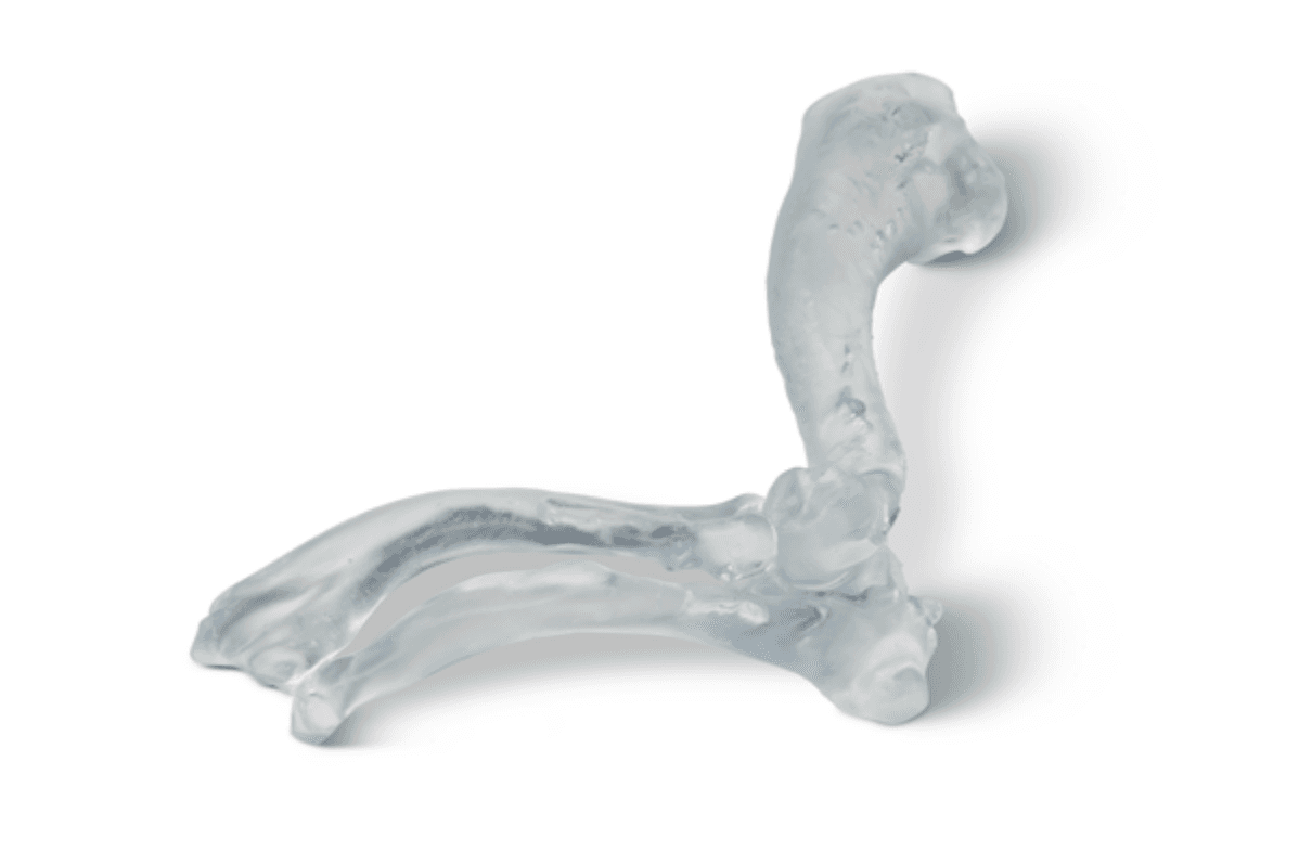
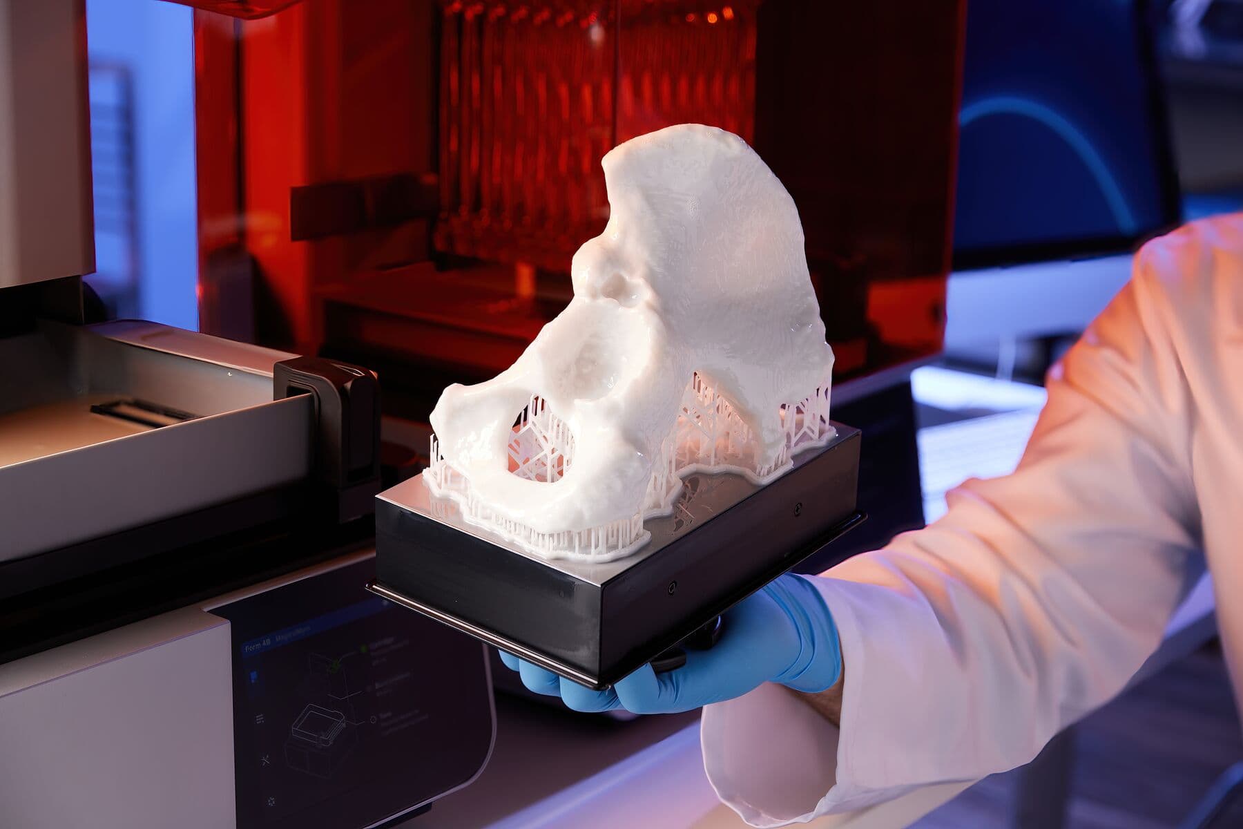
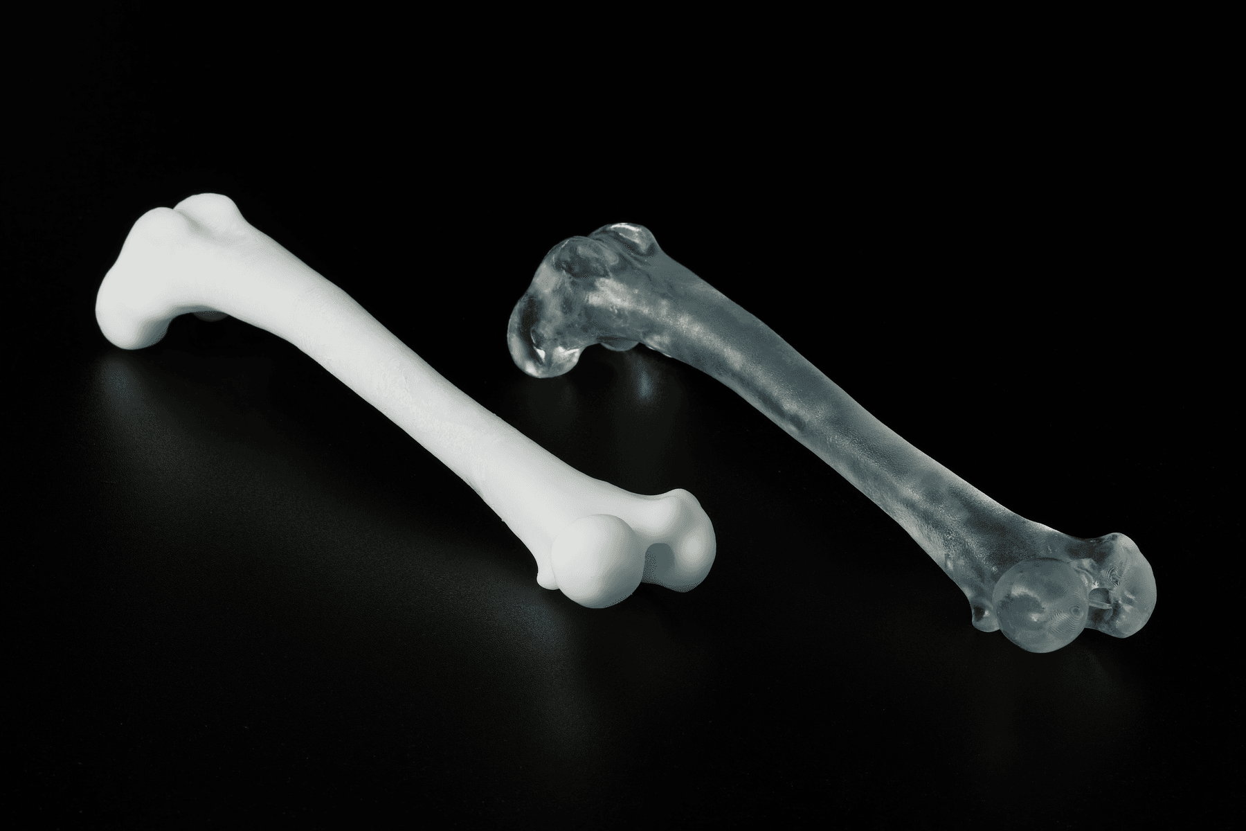
2.2 Select Material

Select the material by clicking the Printer Type box in the Job Info menu on the right-hand side. Select BioMed Durable Resin or Rigid 4000 Resin from the materials grid.

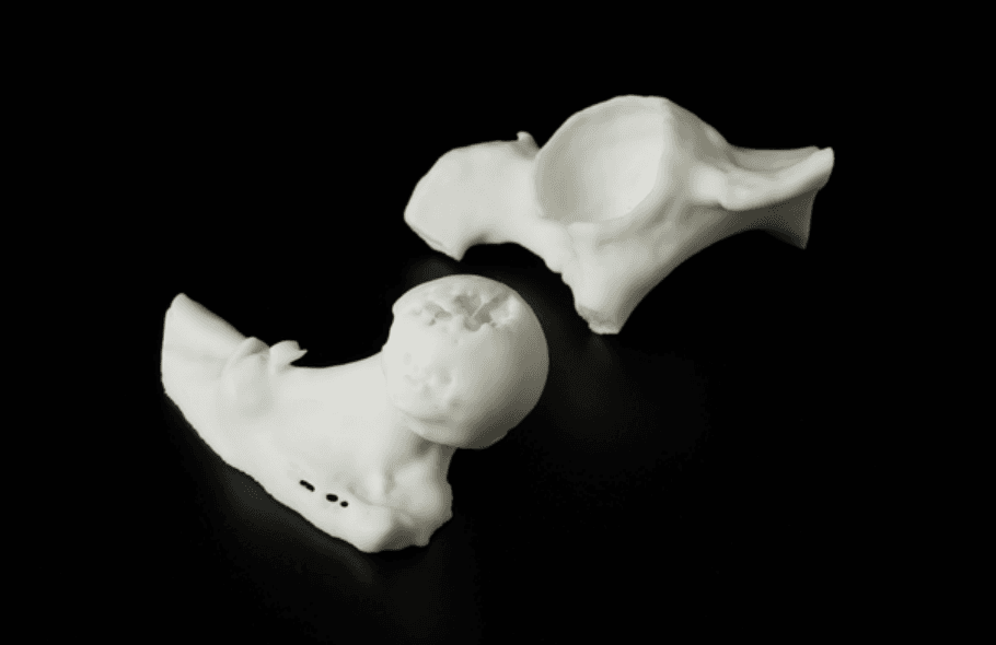
2.3 Hollow and Add Drain Holes

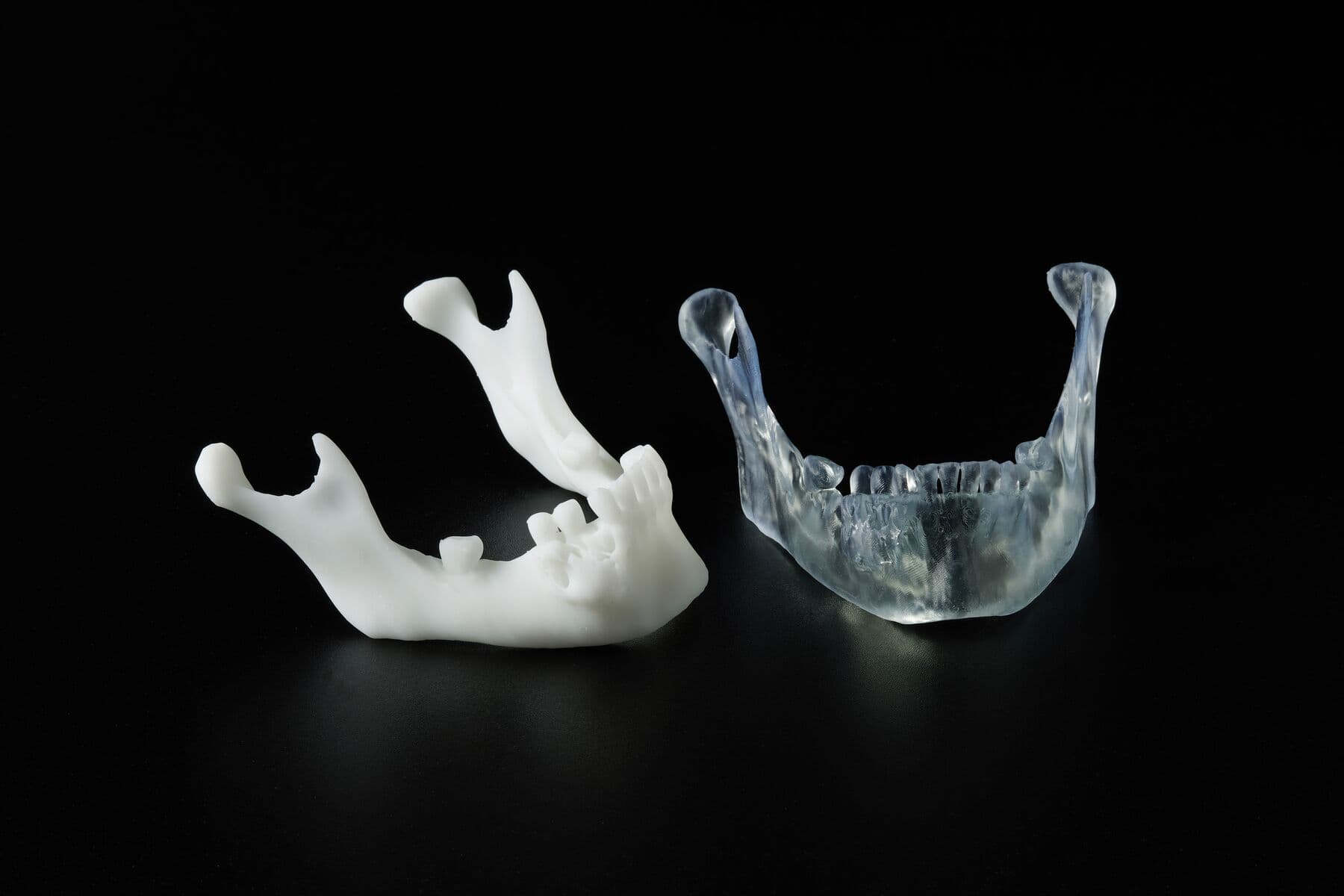
Some users prefer hollow models over solid models for bone simulation. Models can be hollowed and drain holes can be added during the design stage, or using PreForm. To hollow a bone model in PreForm, select the Hollow function on the left side of the PreForm window. Set the wall thickness value to the approximate thickness of compact bone in the bony anatomy being simulated. Drain holes can be added using the Hole function, which is also located on the left side of the PreForm Window.
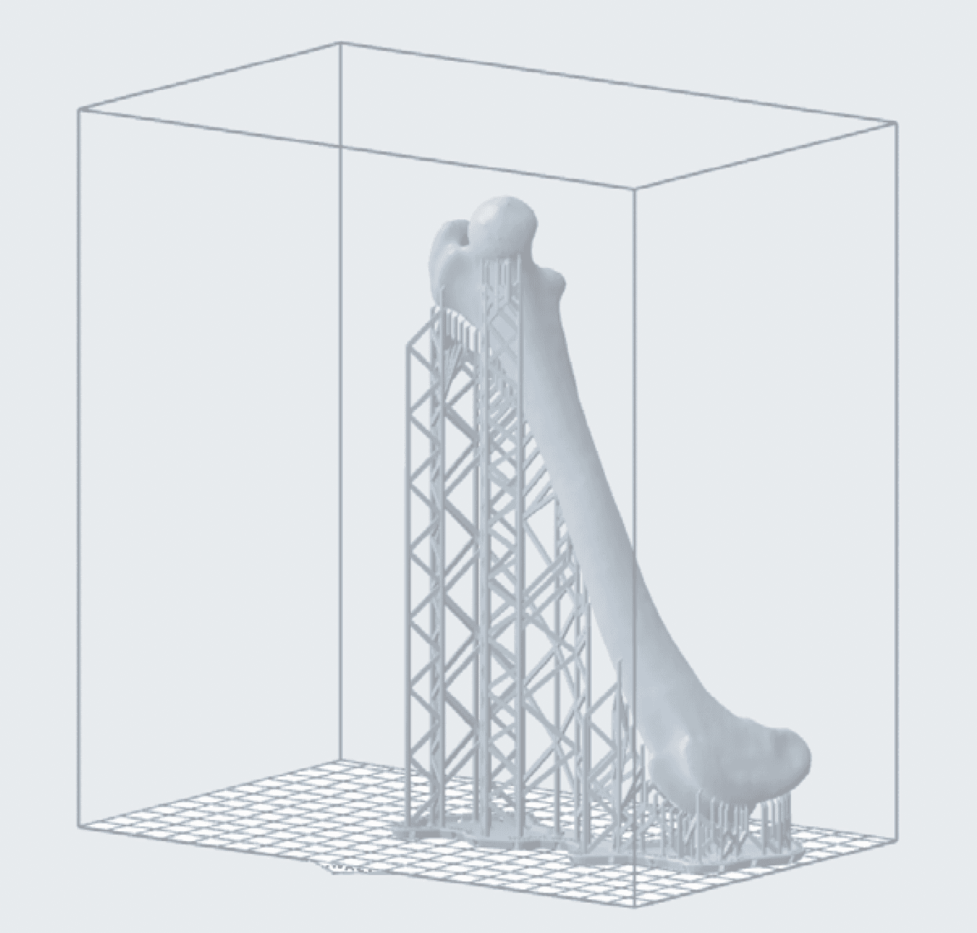
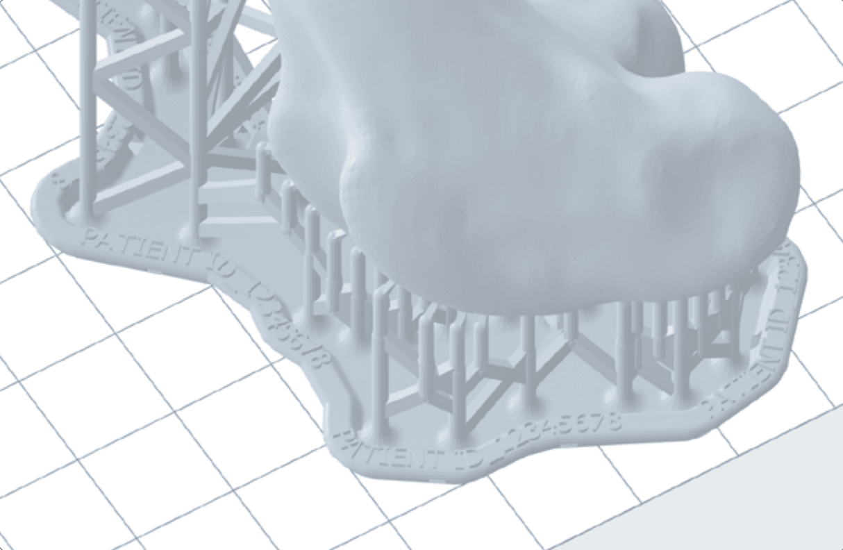
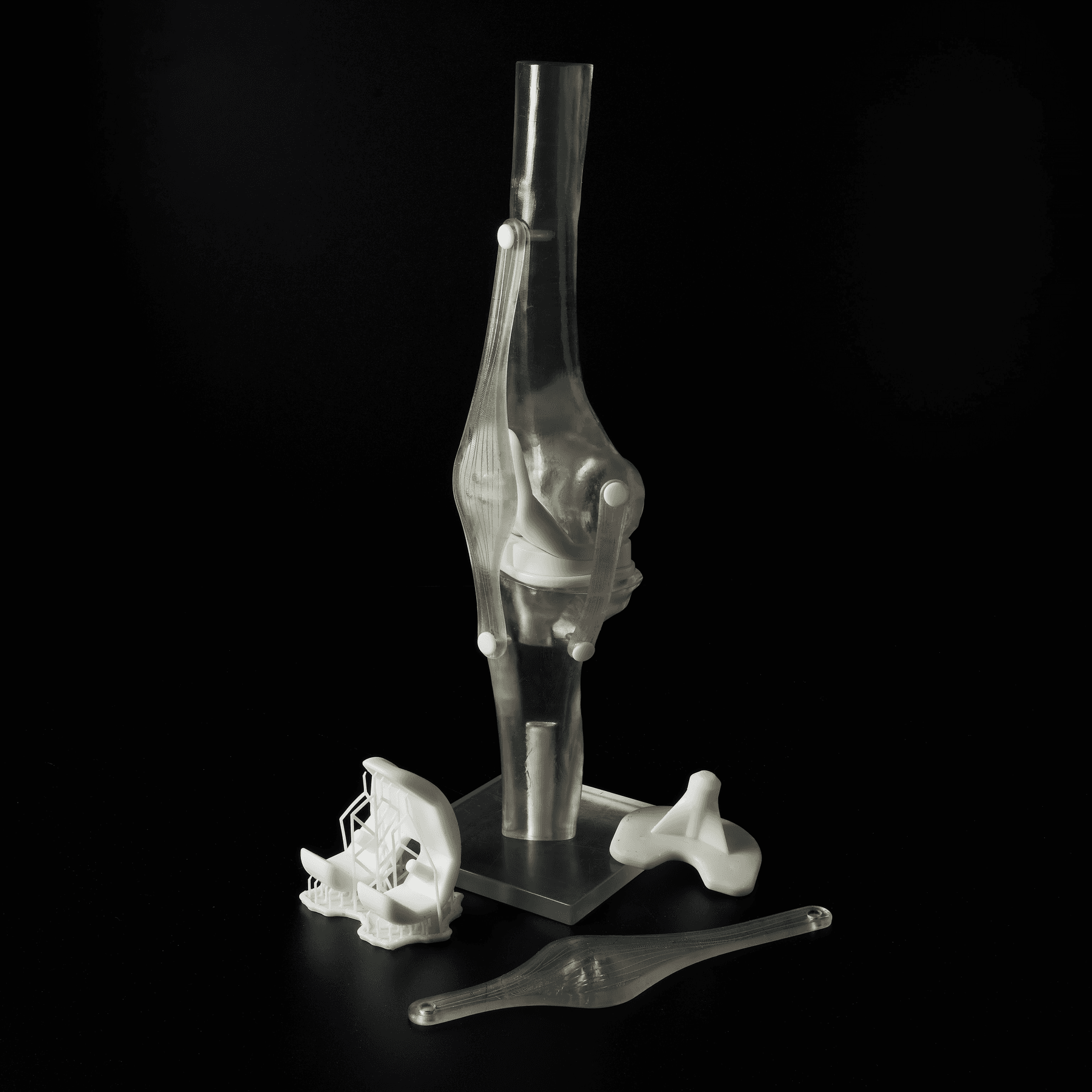
2.4 Orient

PreForm can auto-orient based on Formlabs’ best practices. To auto-orient, select your part and click Orientation on the left side of the screen. Then, click Auto-Orient Selected.

For best results, you should orient manually using the red, green, and blue actuators surrounding your part. Below are some orientation considerations for manually orienting; deviating from these practices increases the risk of print failure:

• Print directly on the build platform whenever possible.

• When printing with supports, orient the part so that it is smaller at the base and then builds on itself. This decreases the likelihood that the print will break away from the supports during printing and increases stability.

• Minimize the number of unsupported minima whenever possible.

• Aim cups away from the build platform to avoid filling with liquid resin while printing and adding more weight to the part.

• Make sure that hollow models are oriented to drain properly. This can be done by orienting at least one drain hole away from the build platform.

• Orient the thinnest part of the object away from the build platform to decrease peel forces and lower the failure rate.

• Flat surfaces should be oriented at an angle. This study conducted at the Mercer University School of Engineering suggests that a 60° angle is ideal for maintaining dimensional accuracy.

• Parts should be angled on more than one axis.

• If there is one side where supports are more acceptable than another, or where surface texture or fine details are less important, this side should be oriented towards the build platform. Areas where supports are undesirable, such as a specific region of interest or surfaces with fine details, should be oriented facing away from the build platform.

• Point junctions between two surfaces down towards the build platform to preserve dimensional integrity at intersections.

• Thoughtful orientation can sometimes be used to fit a large part, or multiple parts, into one build. Choosing an orientation that reduces the size of the print in the X or Y axis may allow you to fit more parts onto one build platform. Space-saving orientations are not based on maximizing print success and thus increase the risk of failure. Ensure proper support placement to compensate.

• Keep the bulk of the part’s weight as close to the build platform as possible to reduce the risk of failure.

• Orient long parts parallel to the front edge of the build platform for easier removal.

preform bone

Example of a preferable orientation for a long part. The steep angle of the print allows for it to be largely self-supporting, resulting in a decreased support density and the ability to fit more parts on the build platform. Model is courtesy of Dr. Desmond Tan with Alfred Veterinary Orthopedics via Alogus Innovation.

2.5 Add Supports

To auto-generate supports based on BioMed Durable Resin’s material properties, select your part, go to Supports on the left side of the screen, and select Auto-Generate All.

For optimal results, we recommend manually editing auto-generated supports, or manually placing supports until the part is sufficiently supported (indicated by a green thumbs-up beside Supports in the Job Setup menu). PreForm will indicate in red what areas might require additional support.

2.6 Add Patient Identifiers

For patient-specific models, patient identifiers may be required. Patient identifiers should be determined using an internal case number or naming scheme. They can be added to the part’s raft by double-clicking the name of the part under Model List in the bottom right corner of the PreForm window, and typing in the patient identifier as the part name. Make sure that the Raft Label box is checked off under Supports. This patient identifier will then be printed on the part’s removable raft and will be saved as the part's name in Formlabs’ online Dashboard. In some scenarios, it may be desirable to have the patient identifier embossed or etched directly into the printed part itself. In this case, the text can be added by clicking Label in the left-hand menu of PreForm.

raft of a patient-specific model

Patient identifier embossed on the raft of a patient-specific model.

2.7 Layout

Set your part’s location on the build platform by clicking and dragging, using the red, green, and blue actuators surrounding your part, or by clicking Layout, then Layout All, on the right side of the screen. It’s best to place parts in the center of the build platform. When printing multiple parts, space on the build platform can be optimized and material can be saved by overlapping rafts.

2.8 Send to the Printer

Send your job to the printer by clicking the orange Upload Print button on the bottom right. When the Print dialogue box opens, select the printer that you would like to use.

2.9 Prepare the Printer

Check that your resin cartridge is within its expiration date. Shake the resin cartridge and then insert it. When using a new cartridge, double-check that the silicone bite valve is opening successfully by squeezing it with a gloved finger. Wearing gloves, insert a build platform and a compatible resin tank into the printer.

Begin printing by selecting your print job from the printer’s touch screen. Follow any prompts or dialogues shown.

WARNING:

For full compliance and biocompatibility, BioMed Durable Resin requires a dedicated resin tank and build platform. Full compliance and biocompatibility may not be necessary for all bone-simulation applications.

3. Post-Processing Parts Printed With BioMed Durable Resin

3.1 Remove the Part

Remove the part from the build platform. On Build Platform Flex or Build Platform 2/L, flex the stainless steel handles towards one another. On a Build Platform, wedge the part removal tool under the part raft and rotate the tool.

3.2 Wash and Remove Supports

Place the part in a Form Wash or Form Wash L filled with 99% isopropyl alcohol (IPA). Over time, IPA that has been used to wash many parts will decrease in concentration and cause parts to remain sticky. Check that your IPA has an acceptable concentration using this procedure.

Wash using the recommended settings for BioMed Durable Resin found here. If the model is hollow or has internal channels, ensure liquid resin is thoroughly flushed out from these features. This can be done using a syringe filled with IPA.

Remove supports by gently pulling at the support structure; they should detach easily. If they are not releasing easily, or you are worried about causing damage to your parts by pulling, you may use flush cutters, a hobby knife, or an ultrasonic cutter to cut the supports at their attachment point.

After the supports have been removed, wash again for 10 minutes. Allow parts to dry fully by leaving them to sit for one hour. Not allowing parts to dry fully may result in tacky parts.

WARNING:

For full compliance and biocompatibility, BioMed Durable Resin requires a dedicated Form Wash or Form Wash L. Only use this Form Wash or Form Wash L with other Formlabs biocompatible resins.

3.3 Post-Cure

Place the part in the Form Cure or Form Cure L and cure according to the time and temperature settings found here.

WARNING:

For full compliance and biocompatibility, BioMed Durable Resin requires a dedicated Form Cure or Form Cure L. Only use this Form Cure or Form Cure L with other Formlabs biocompatible resins.

completed veterinary model printed in BioMed Durable Resin

A completed veterinary model printed in BioMed Durable Resin, courtesy of Dr. Desmond Tan with Alfred Veterinary Orthopedics via Alogus Innovation.

4. Post-Processing Rigid 4000 Resin

4.1 Remove the Part

Remove the part from the build platform. On Build Platform Flex or Build Platform 2/L, flex the stainless steel handles towards one another. On a Build Platform, wedge the part removal tool under the part raft and rotate the tool.

Ilium model printed in Rigid 4000 Resin straight out of Form 4B

Ilium model printed in Rigid 4000 Resin straight out of Form 4B.

4.2 Wash and Remove Supports

Place the part in the Form Wash filled with 99% IPA or Resin Washing Solution (for non-biocompatible resins only). Over time, IPA that has been used to wash many parts will decrease in concentration, causing parts to remain sticky. Check that your IPA has an acceptable concentration using this procedure.

Wash using the recommended settings for Rigid 4000 Resin found here. If the model is hollow or has internal channels, ensure liquid resin is thoroughly flushed out from these features. This can be done using a syringe filled with IPA or Resin Washing Solution, depending on which is being used.

Remove supports by gently pulling at the support structure; they should detach easily. If they are not releasing easily, or you are worried about causing damage to your parts by pulling, you may use flush cutters, a hobby knife, or an ultrasonic cutter to cut the supports at their attachment point.

4.3 Post-Cure

Place the part in the Form Cure or Form Cure L and cure at 0 °C (room temperature) for 15 min. These recommended settings are different from those typically recommended for Rigid 4000 Resin. By not using heat, only the surface level of the part experiences post-curing, resulting in a more bone-like mechanical performance.

Ball-in-socket joint printed in Rigid 4000 Resin

Ball-in-socket joint printed in Rigid 4000 Resin and cured without heat.

Biocompatibility and Sterilization

BioMed Durable Resin is an ISO 10993 and USP Class VI certified material. It is made in an FDA-registered, ISO 13485 facility and can be used in applications for long-term skin and mucosal membrane contact (>30 days), and for externally communicating devices in short-term contact with tissue/bone/dentin (≤24 hours). Sterilization guidelines and results for BioMed Durable Resin are available upon request.

Rigid 4000 Resin is a standard engineering material and was not developed with medical applications specifically in mind. For this reason, Rigid 4000 Resin has not been tested for biocompatibility and does not currently have sterilization/disinfection guidelines.

Next Steps

Formlabs is exploring how to make our bone-simulation models even more realistic. We’re currently investigating ways to create different internal and external mechanical properties, differentiating compact from spongy bone, and using complex geometries and alternative post-processing techniques. If you have experience in this area, reach out to [email protected].

Bone-simulation model

Bone-simulation model utilizing parts printed in multiple materials.

Acknowledgments

We’d like to extend our gratitude to the following contributors for graciously lending their valuable time and insights to developing this application guide:

  • Dr. Tobias Dust and his colleagues at the Clinic for Trauma Surgery and Orthopedics, University Medical Center Hamburg-Eppendorf
  • Joseph Alfano, David McCloskey, and Claire Romanczyk at Alogus Innovation
  • Dr. Desmond Tan with Alfred Veterinary Orthopedics/Sirius Veterinary Orthopedic Center
  • Dr. Joshua Jackson at Bridger Veterinary Specialists
  • Dr. William “Mike” Karlin at the Cummings School of Veterinary Medicine, Tufts University
  • Dr. Prashanth Ravi, Dr. Frank Rybicki, and Shayne Kondor at the University of Cincinnati Department of Radiology
  • Dr. Lauren Schlegel at Beth Israel Deaconess Medical Center
Veterinary femur bone models

Veterinary femur models printed in Rigid 4000 Resin and cure without heat (left) and BioMed Durable Resin (right), courtesy of Dr. Desmond Tan with Alfred Veterinary Orthopedics via Alogus Innovation.

Do you have questions about using SLA printing for creating bone-simulation models? Set up a meeting with a Formlabs expert who can answer your questions.

Request a free sample part to see Formlabs 3D printed materials firsthand and contact our 3D printing specialist to find the right solution for your application.