
Composite materials, such as carbon fiber-reinforced plastics, are highly versatile and efficient materials, driving innovation in various markets from aerospace to healthcare. They outperform traditional materials such as steel, aluminum, wood, or plastic, and enable the fabrication of high-performance lightweight products.
In this guide, learn the basics of manufacturing carbon fiber parts, including the different carbon fiber layup, lamination, and molding methods, and how you can use 3D printing to make carbon fiber molds to lower costs and save time. Directly 3D printed composites exist as well, such as Formlabs Nylon 11 CF Powder, which is a carbon fiber-filled material that is perfect for applications that require both superior stiffness and strength. When printed on the Formlabs Fuse 1+ 30W printer, Nylon 11 CF Powder produces lightweight, rigid parts that remain structurally and thermally stable and can sustain repeated impact.
Request a Free Nylon 11 CF Powder Sample Part
See and feel the quality of carbon fiber-filled nylon firsthand. We’ll ship a free sample part to your office.
Composite Materials 101
A composite material is a combination of two or more constituents with characteristics different from those individual components by themselves. Engineering properties are typically improved, such as added strength, efficiency, or durability. Composites are made of reinforcement - fiber or particle - held together by a matrix (polymer, metal, or ceramics).
Fiber-reinforced polymers (FRP) dominate the market and have fueled the growth of new applications in various industries. Among them, carbon fiber is a widely used composite in particular for aircraft, racing cars, and bicycles as it is more than three times stronger and stiffer than aluminum, but 40% lighter. It is formed by reinforced carbon fiber linked with an epoxy resin.
Fibers can be directionally uni-weave and strategically aligned to create strength relative to a vector. Cross woven fibers can be used to create strength in multiple vectors and they are also responsible for the signature quilted look of composite parts. It is common for parts to be produced with a combination of both. There are multiple types of fibers available, including:
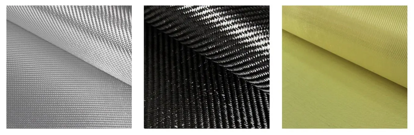
| Fiberglass | Carbon fiber | Aramid fiber (Kevlar) |
|---|---|---|
| The most popular fiber Lightweight, moderate tensile and compressive strength Low cost and easy to work with | Highest strength and stiffness-for-weight ratio in the industry (ultimate tensile, compressive, and flexural strength) More expensive than other fibers | Higher impact and abrasion resistance than carbon fiber Low compressive strength Difficult to cut or machine |
Resin is used to hold these fibers together and create a rigid composite. While hundreds of types of resins can be employed, here are the most popular ones:
| Resin | Pros | Cons | Curing |
|---|---|---|---|
| Epoxy | Highest ultimate strength Lightest weight Longest shelf life | Most expensive Sensitive to mix ratio and temperature variations | Uses a specific hardener (two-part system) Some epoxies require heat |
| Polyester | Easy to use (most popular) UV resistant Lowest cost | Low strength and corrosion resistance | Cures with a catalyst (MEKP) |
| Vinyl Ester | Mixes the performance of epoxy and the cost of polyester Best corrosion, temperature resistance, and elongation | Lower strength than epoxy and higher cost than polyester Limited shelf life | Cures with a catalyst (MEKP) |
Book a Free Consultation
Get in touch with our 3D printing experts for a 1:1 consultation to find the right solution for your business, receive ROI analyses, test prints, and more.
Three Methods for Creating Carbon Fiber Parts
Manufacturing fiber-reinforced polymers, such as carbon fiber parts is a skillful and labor-intensive process used in both one-off and batch production. Cycle time ranges from one hour to 150 hours depending on the size and complexity of the part. Typically in FRP fabrication, the continuous straight fibers are joined in the matrix to form individual plies, which are laminated layer-by-layer onto the final part.
The composite properties are induced by the materials as much as the laminating process: the way the fibers are incorporated strongly influences the performance of the part. The thermoset resins are shaped together with the reinforcement in a tool or mold, and cured to form a robust product. There are various laminating techniques available, which can be differentiated into three main types:
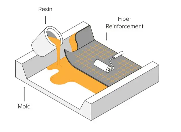
1. Wet Lay-Up
In wet lay-up, the fiber is cut and laid into the mold then resin is applied via a brush, roller, or spray gun. This method requires the most skills to create high-quality parts, but it is also the least expensive workflow with the lowest requirements to get started with making DIY carbon fiber parts. If you are new to carbon fiber parts manufacturing and not equipped yet, we would recommend starting with wet lay-up hand lamination.
Watch the video to see how the wet carbon fiber lay-up process works.
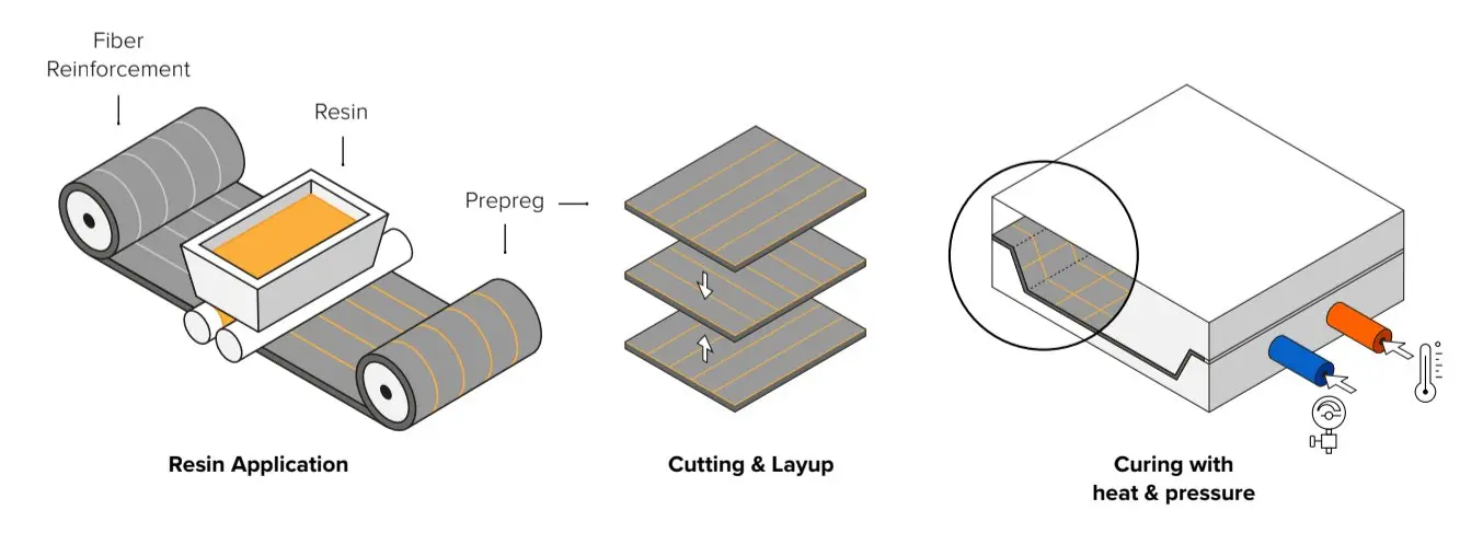
2. Prepreg Lamination
With prepreg lamination, the resin is infused in the fiber ahead. Pre-impregnated sheets are stored cold to inhibit the cure. Plies are then cured into the mold under heat and pressure in an autoclave. This is a more precise and repeatable process because the quantity of resin is controlled but it is also the most expensive technique that is usually used in high-performance applications.
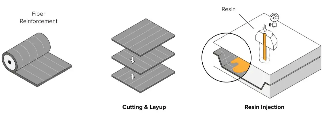
3. Resin transfer molding (RTM)
With RTM molding, the dry fiber is inserted into a two-part mold. The mold is clamped shut before forcing the resin into the cavity at high pressure. It is usually automated and used for larger volume manufacturing.
Creating Molds for Carbon Fiber Parts Manufacturing with 3D Printing
Because the quality of the mold directly impacts the quality of the final part, tool making is a critical aspect of FRP manufacturing. Most molds are produced out of wax, foam, wood, plastic, or metal via CNC machining or handcrafting. While manual techniques are highly labor-intensive, CNC machining still follows a complex, time-consuming workflow—especially for intricate geometries—and outsourcing typically comes at a high cost, with a long lead time. Both options require skilled workers and offer little flexibility on design iterations and mold adjustments.
Additive manufacturing offers a solution for rapidly producing molds and patterns at low costs for making carbon fiber parts. The use of polymeric tooling in manufacturing processes is growing continuously. Replacing metal tools with plastic parts printed in-house is a powerful and cost-effective means to shorten production time while expanding design flexibility. Engineers already work with polymer resin 3D printed parts for manufacturing jigs and fixtures to support methods such as filament winding or automated fiber placement. Likewise, short-run printed molds and dies are employed in injection molding, thermoforming or sheet metal forming to deliver low-volume batches.
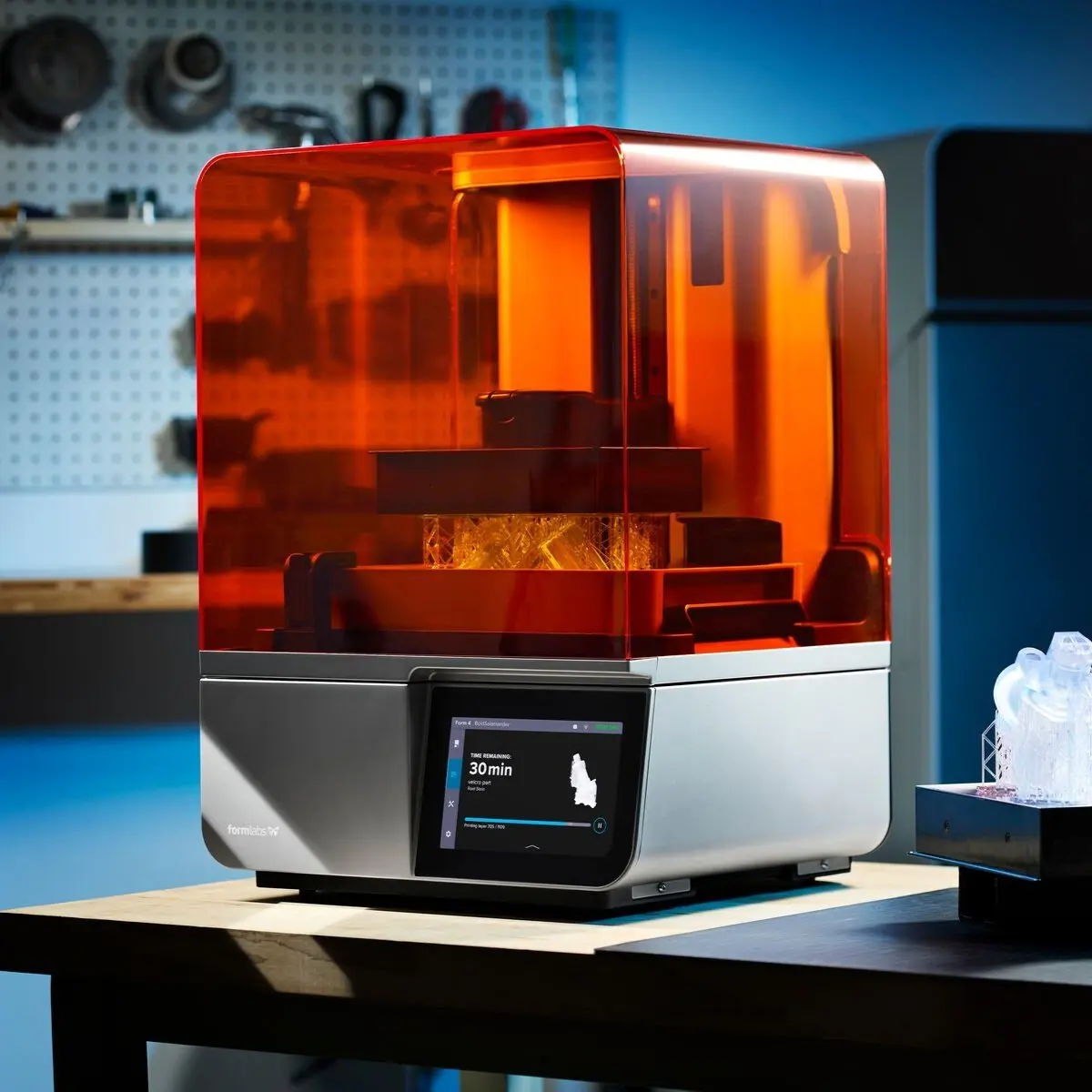
In-house desktop 3D printing requires limited equipment and reduces workflow complexity. Professional desktop resin printers like Form 4 are affordable, easy to implement, and can be quickly scaled with the demand. Manufacturing large tools and molds is also possible with large format 3D printers such as Form 4L.
Stereolithography (SLA) 3D printing technology creates parts with a very smooth surface finish, which is essential for carbon fiber layup molds. It allows for complex geometries with high precision. Additionally, the Formlabs Resin Library has engineering materials with mechanical and thermal properties that pair well with mold and pattern manufacture.
3D printed molds for manufacturing carbon fiber parts can reduce costs and lower lead times.
For small-scale production, engineers can directly print the mold at low costs and within a few hours without having to hand carve it or deal with CNC equipment; CAM software, machine setup, workholding, tooling, and chip evacuation. Labor and lead time for mold fabrication are drastically reduced, allowing for quick design iteration and parts customization. They can achieve complicated mold shapes with fine details that would be difficult to manufacture with traditional methods.
Mold Architecture and Design Guidelines
When designing your mold, consider what will print successfully, as well as what will mold successfully. Different mold architectures are used to create different types of geometry:
- One-part mold in vacuum bagging: Used for parts that need one class A side, meaning a glossy finish. It can be positive or negative, depending on which side should be class A. One side is the mold surface, the other side is the vacuum bag surface.
- Two-part mold in compression molding: Used for parts where both sides of the part need to be class A. Both sides are mold surfaces.
- Bladder mold in pressure molding: Used for complex geometry where a vacuum bag or compression mold can not be employed due to the inability of the part to demold. One side is the mold surface, while the other side is the bladder surface.
- Mold pattern to create a negative mold: Used when multiple molds are desired to increase production. Multiple molds can be made from a single pattern.

Add draft angle: Two to three degrees of positive draft angle will facilitate the demolding step and increase the life of the mold, in particular for stiff molds. However, using a pliable 3D printing material such as Tough 1500 Resin can permit you to create parts without a draft and include challenging geometries that could not be demolded from a stiff mold. Set a minimum radius appropriate for your material thickness: this helps the fibers to align on corners while avoiding air inclusion, and to create repeatable quality parts. Avoid steep and close proximity corners, as flowing geometries are easier to work with than boxy, edgy ones.
Set a minimum radius appropriate for your material thickness: This helps the fibers to align on corners while avoiding air inclusion, and to create repeatable quality parts. Avoid steep and close proximity corners, as flowing geometries are easier to work with than boxy, edgy ones.

Include locating pins and indents for molds that require precise alignment. One of the great advantages of 3D printing is that it allows for complexity in alignment geometry and helps to fabricate designs sensitive to positioning.
Include surface overrun: excess material from the extended surface will be cut down to draw a precise trim line. 3D printing allows you to print in overrun without needing to fabricate flashing.
Add trim lines: 3D printing permits you to incorporate precise grooming features such as drill guides, scribe lines for hand trimming, or router guide rails.
Other best practices:
- Print at the smallest layer height possible to optimize the resolution and demolding step.
- Avoid supports on molding faces for better surface finish.
- Use a release agent: this is required to enable the demolding process.
- To avoid air inclusion: after stirring and mixing, wait two minutes to have the air settle out of the resin. Reiterate after brushing on the first layer of resin. If small air bubbles remain, it can be polished out and sealed off in post-processing.
Case Study: TU Berlin 3D Prints Carbon Fiber Molds

The Formula Student is a yearly engineering design competition in which student teams from around the world build and race formula-style cars. The Formula Student Team TU Berlin (FaSTTUBe) is one of the largest groups; 80 to 90 students have been developing new racing cars every year since 2005.
The Formula Student team at TU Berlin (FasSTTUBe) is building three vehicles for the annual Formula Student competition.
With access to nearly the full range of fabrication technologies, the FasSTTUBe team is using 3D printing for three purposes:
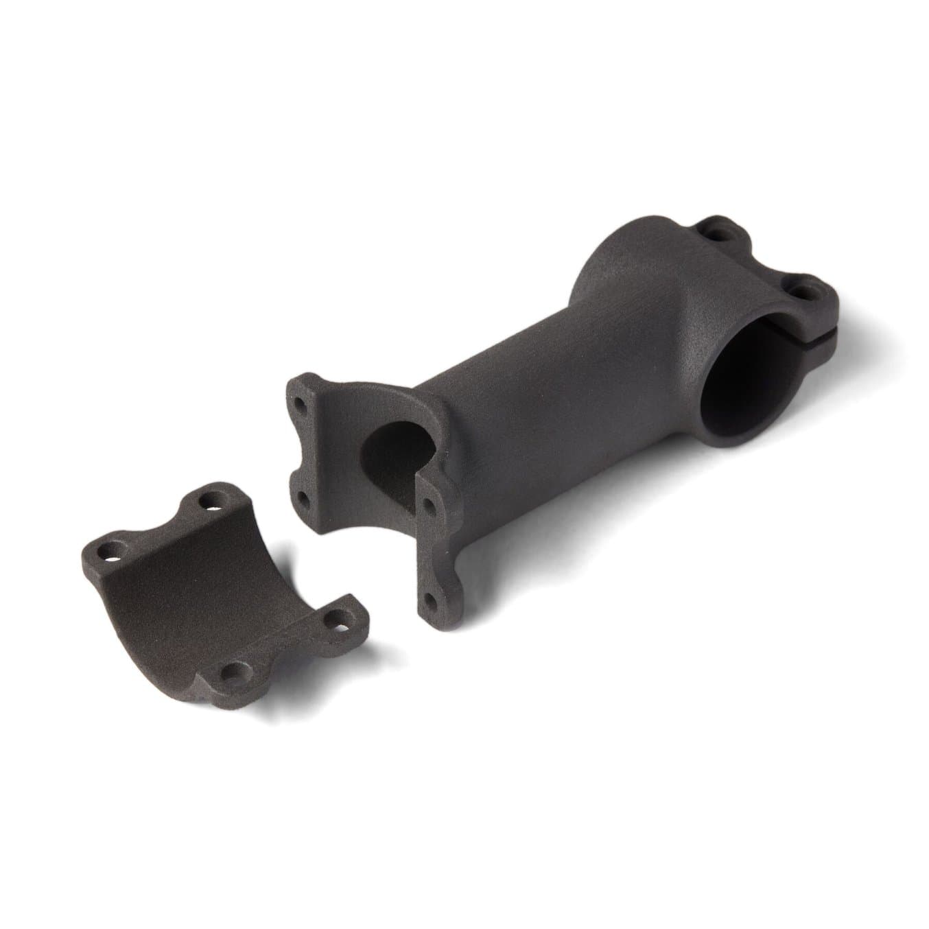
- Prototypes: they print prototypes for various parts, such as mountings of the anti-roll bar or stakeholders of the HV Battery.
- 3D printed carbon fiber molds: the team printed a dozen molds to fabricate carbon fiber parts that could not have been made otherwise.
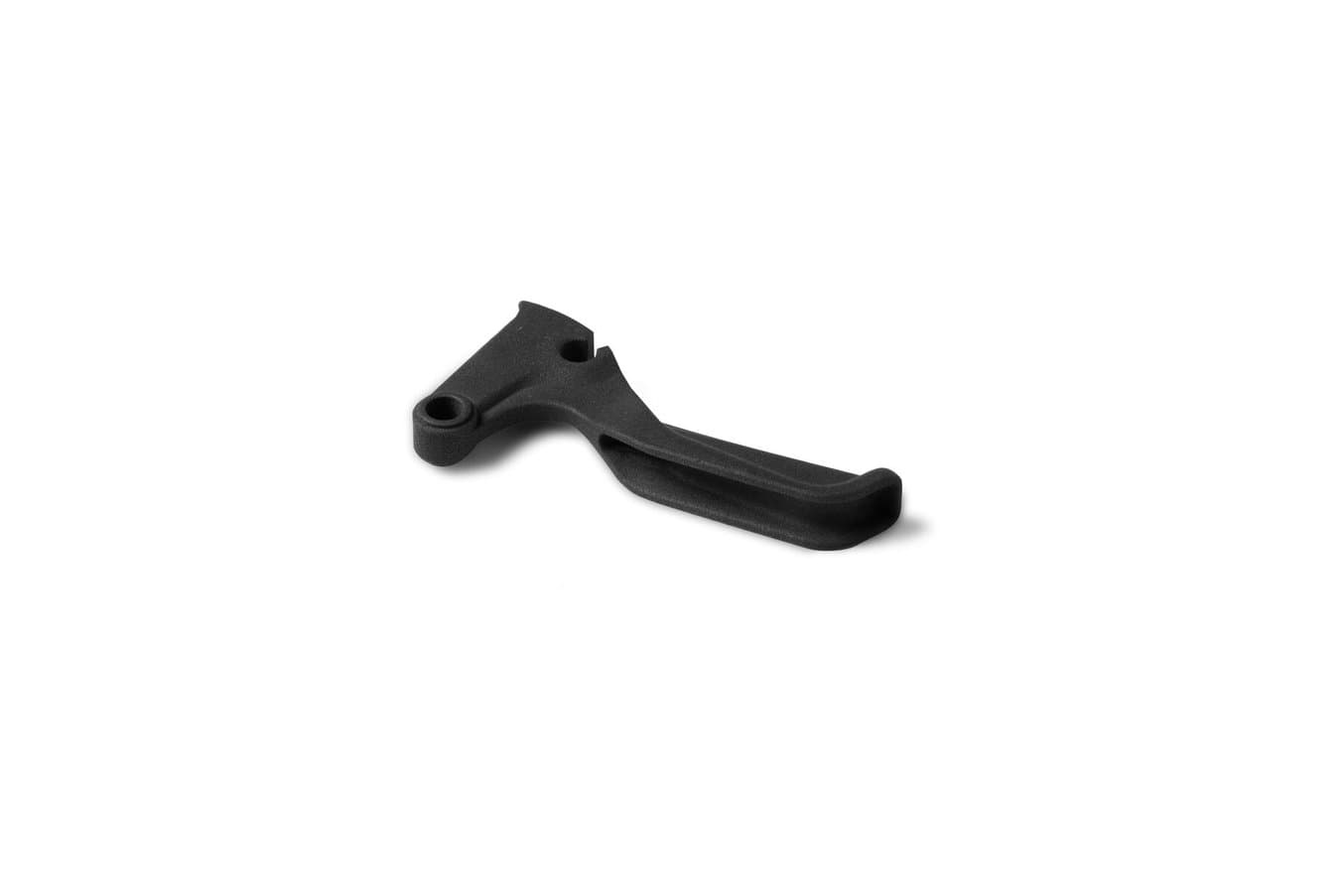
- End-use parts: about 30 parts on the final vehicles are directly 3D printed: from button holders, shifters of the steering wheel, to hoses and sensor connectors of the cooling systems.
In this case study, we’re looking into the details of the molding application they used to fabricate the steering wheel housing and grips in carbon fiber.
Reducing weight is essential in the construction of racing cars. In an effort to lighten the parts, they could have printed hollow steering wheel grips, but it would not be strong enough to bear the grasp of the driver. Carbon fiber is a great material to lower weight while maintaining or increasing strength. To be able to fabricate the part in carbon fiber this year, Felix Hilken, the Head of Aerodynamics and Carbon Manufacturing, developed a workflow using 3D printed molds for wet lay-up lamination.
Equipment Necessary:
- Formlabs SLA 3D printer with Tough 1500 Resin
- Carbon fiber: three layers of 200g, 3K, 0,3mm, twill weave pattern
- Mold release: wax and polyvinyl alcohol
- High-strength epoxy resin
- Brush and scissors
- Vacuum bag, vacuum pump, and breather cloth
- Sandpaper

1. Design the Mold
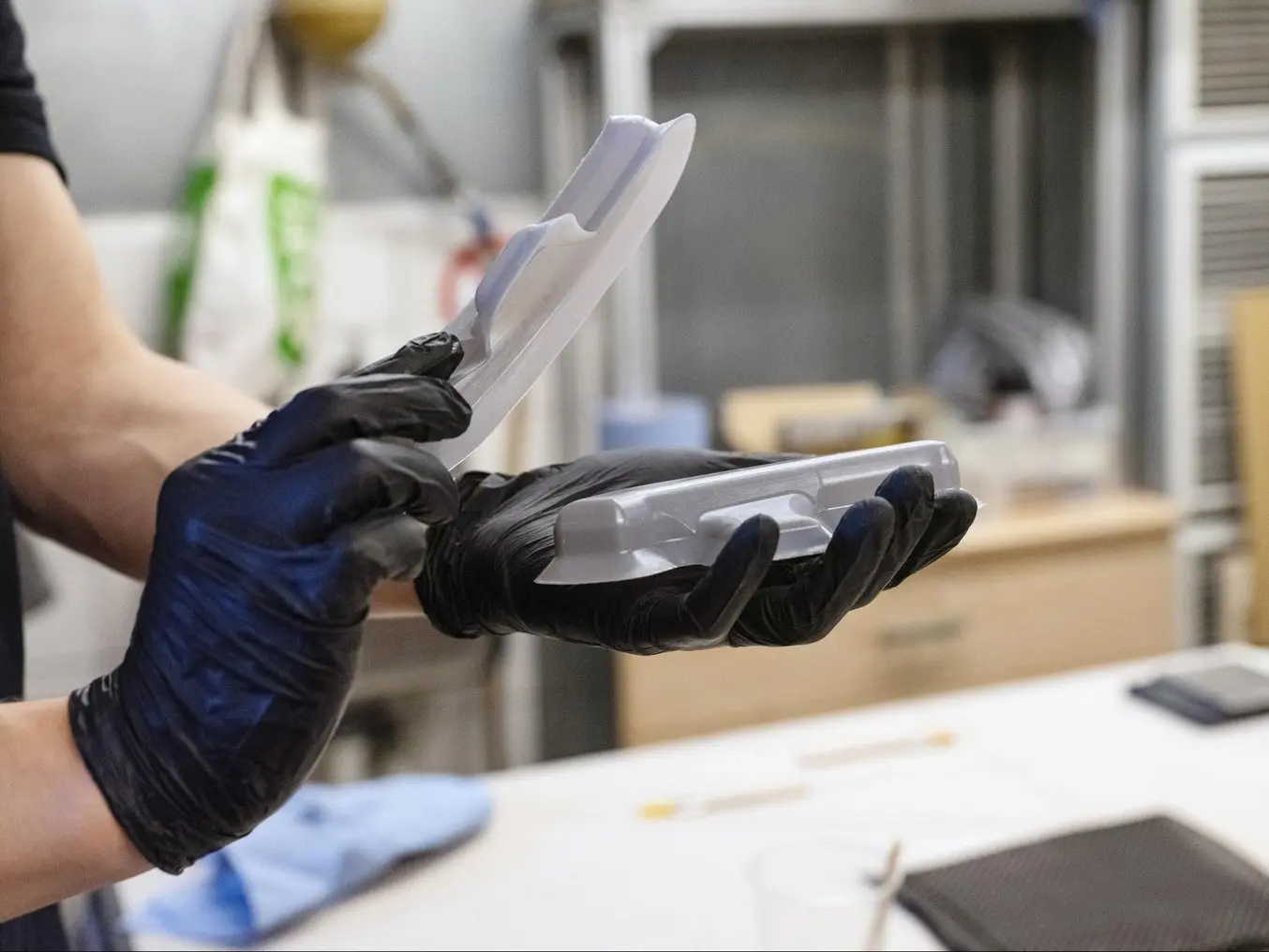
The grip was manufactured in two halves in order to be able to demold the part. For each half of the grip, Felix designed a two-part mold including features that would be challenging to manufacture without 3D printing, in particular:
- Fine features such as tight internal radii, sweeping surfaces, or varying radii surfaces
- Round tight edges that could not be demolded from an aluminum mold
- Indents for drilling location because the part is sensitive to positioning

2. 3D Print the Mold
The team printed the molds on the Form Series printer with Tough 1500 Resin at a 50 microns layer height. The prints were washed for two periods of 10 minutes in IPA and post-cured for 60 minutes at 70 °C. Tough 1500 Resin was chosen because it balances elongation and modulus: parts printed in this material can bend significantly and quickly spring back to their original shape. This is a desired mechanical property to avoid mold breakage while demolding.

3.1 Hand Laminate: Apply Release Agent
Apply release agent to facilitate the demolding process. This is a critical first step: if some surfaces are not covered, the part will not separate from the mold.
- Cover with wax (optional but recommended)
- Cover with polyvinyl alcohol (PVA)

3.2 Mix Resin and Hardener
Mix the resin with the hardener. The mixing ratio must be precisely followed. If it is off by even a few percent of the target ratio, the part will be either too soft or only partially cured. Follow the instructions of the resin manufacturer closely and read the safety sheet before use. With the resin Felix used, the polymerization process starts two hours after the resin is mixed, which leaves two hours for the layup operation.

3.3 Apply Resin
Apply resin with a brush on the positive side of the mold.

3.4 Lay-Up Carbon Fiber
Lay up a carbon fiber ply on the positive side of the mold. Make sure to follow all the contours. The team used a 3K fiber to balance weave thickness and price. It is specifically designed to follow complex contours and does not have supporting strands in it.

3.5 Apply Resin on the Carbon Fiber
Apply resin on the carbon ply and reiterate the layup process. The resin bonds the layers together, forming the matrix component in the part, and prevents the fiber from realigning. Felix used three carbon fiber plies.

3.6 Apply Final Resin to Negative
Apply a final layer of resin on the negative part of the mold and press both halves of the mold together to avoid air bubbles forming and permeating through the fibers.

3.7 Remove Extra Material
Cut off the extra material using scissors.

3.8 Cure
Cure for 48 hours in a vacuum bag. During this polymerisation process, the vacuum bag pulls out the air and presses the plies against the mold, at ambient temperature, to get rid of excess resin. It ensures a desired volumetric resin to fiber ratio, to match the right part stiffness.

4. Post Process and Finish
Finishing: sand off all the edges. In order to clean the mold after the process, Felix dipped it in water for about 30 minutes to dissolve the PVA and then used fine 1500 grit sandpaper to remove the leftover resin.
Results
By using carbon fiber, the team reduced the weight of the steering wheel housing from 120g to 21g, and they were able to push the design to geometries that would be extremely difficult to manufacture traditionally. “The great thing about 3D printing is that a complex shape is as easy to manufacture as a simple one, it requires the same amount of work and equipment,” says Felix.
Without 3D printing, the team would have had to outsource the CNC milling of an aluminum mold, which is expensive, has a long lead time, and requires specialized tools. “I would CNC machine the mold, I would need to get specialized tools, and wait to get a slot on the machine. But I could not even do this geometry. In particular some of the small corners. I would need to use a design that doesn't have any screws in it, so the part would not be sensitive to positioning."
From his estimation, one mold printed with Formlabs Tough 1500 Resin could be used to fabricate about ten parts. As this is a manual process, it depends on how meticulous the operator is: the mold can break during the separation process. However, multiple 3D printed molds can be used to increase production. Another solution to extend the lifetime of the mold would be to support it with a metallic generic mold. A 3D printed insert carries the geometry while a backup metallic mold helps to hold its shape. This could be fabricated with a simple manual milling machine.
| Outsourced CNC Machined Mold | In-House 3D Printed Mold | |
|---|---|---|
| Equipment | Carbon fiber, resins, tools, vacuum bag | Carbon fiber, resins, tools, vacuum bag, 3D printer, Tough 1500 Resin |
| Mold Production Time | 4-6 weeks | 2 days |
| Labor Costs | $0 | $300 |
| Material Costs | $0 | $10 |
| Total Mold Production Costs | $900 | $310 |
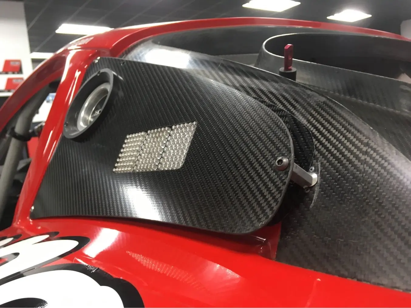
Case Study: Automotive Carbon Fiber Parts for Panoz
DeltaWing Manufacturing creates composite parts for the company Panoz, a designer and manufacturer of exclusive, American-made luxury sports cars. To fabricate carbon fiber components, DeltaWing Manufacturing used to machine a pattern, layup or cast a mold on it, and finish the mold before applying the prepreg process to laminate the carbon fiber part.
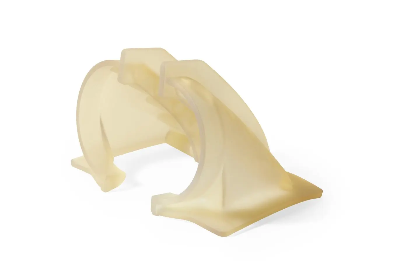
In the past years, they started using in-house 3D printed parts as an intermediate step in this process. Panoz needed six units of a carbon fiber fender air duct for a custom racing car. In order to reduce labor and lead time from their traditional mold making technique, the engineers from DeltaWing Manufacturing chose to directly 3D print the mold and implement it in their prepreg process.
Equipment Necessary:
- Formlabs SLA 3D printer with High Temp Resin
- Carbon fiber: 4K, bidimensional pattern
- Mold release: polyvinyl alcohol
- Kapton (polyimide) tape
- High-strength epoxy resin
- Brush and scissors
- Vacuum bag, vacuum pump

1. Design the Mold
The duct was fabricated in two distinct pieces on two different molds in order to facilitate the separation of the final part from the mold, and then subsequently bonded. Each mold was also printed in two pieces and assembled together so that it could fit in the build volume of the Form Series printer — however, this would not be necessary with the larger build volume of the Form 4L printer. The parts were designed for additive manufacturing, following mold design recommendations.

2. 3D Print the Mold
DeltaWing printed the molds in High Temp Resin on a Form Series printer at 100 micron layer height. This resin was selected because it has a heat deflection temperature (HDT) of 238 °C @ 0.45 MPa, the highest among Formlabs resin and one of the highest among resins on the market.
High Temp Resin can withstand high curing temperatures, shows a good stiffness to hold shape during the operation and a great level of details that will be translated into the final part. Formlabs recommends washing High Temp Resin prints with IPA for 10 minutes, post-cure at 80 °C for 120 minutes, and then heat the parts for 3 hours at 160 °C for a higher HDT.

3. Prepreg Laminate
DeltaWing Manufacturing applied their usual prepreg process on the printed molds, using a prepreg 4K bidimensional pattern fiber. Each mold was covered in Kapton tape in order to renew the surface at each molding iteration. The fiber was laid up on the molds, and then the parts were put in a vacuum bag and cured in an autoclave before demolding and trimming. The printed molds tolerated a slow cure at 38 °C (100 °F) for 10 hours, or alternatively, a fast cure at 126 °C (260 °F) for one hour without damage. Both halves of the carbon duct were bonded in a final step.
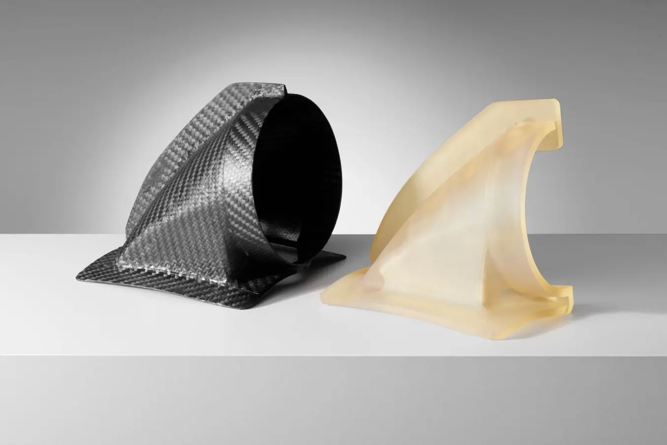
Finish and Results
The team tested six iterations for one mold without observing any significant degradation. We estimate around 10-15 iterations are possible for one mold. As autoclaves are used to apply heat and pressure during curing in the prepreg process, the printed mold can only withstand a few iterations. Therefore, this method is not recommended for high-volume production, but it is a great way to produce short-run batches and mass-customized parts. This enables a wide range of applications such as high-performance sports equipment, customized tooling for aerospace, or personalized prosthetics that are unique to the patients in healthcare.
Carbon Fiber 3D Printing
There is strong demand for workflows that combine the strength, durability, and ruggedness of traditional carbon fiber parts with the agility, geometric possibilities, and repeatability of 3D printing. It’s therefore not surprising that there are many 3D printing companies that offer carbon fiber 3D printing, with the two currently available processes being printing with chopped fibers or continuous fibers.
Using chopped carbon fibers, Nylon 11 CF Powder for the Fuse 1+ 30W selective laser sintering (SLS) industrial 3D printer enables manufacturers to create strong, lightweight, and heat-resistant parts, without relying on traditional overlay or machining methods.
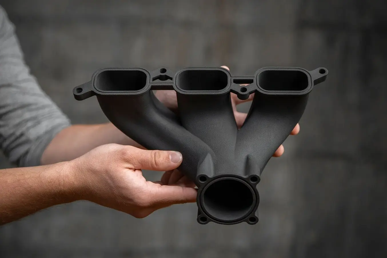
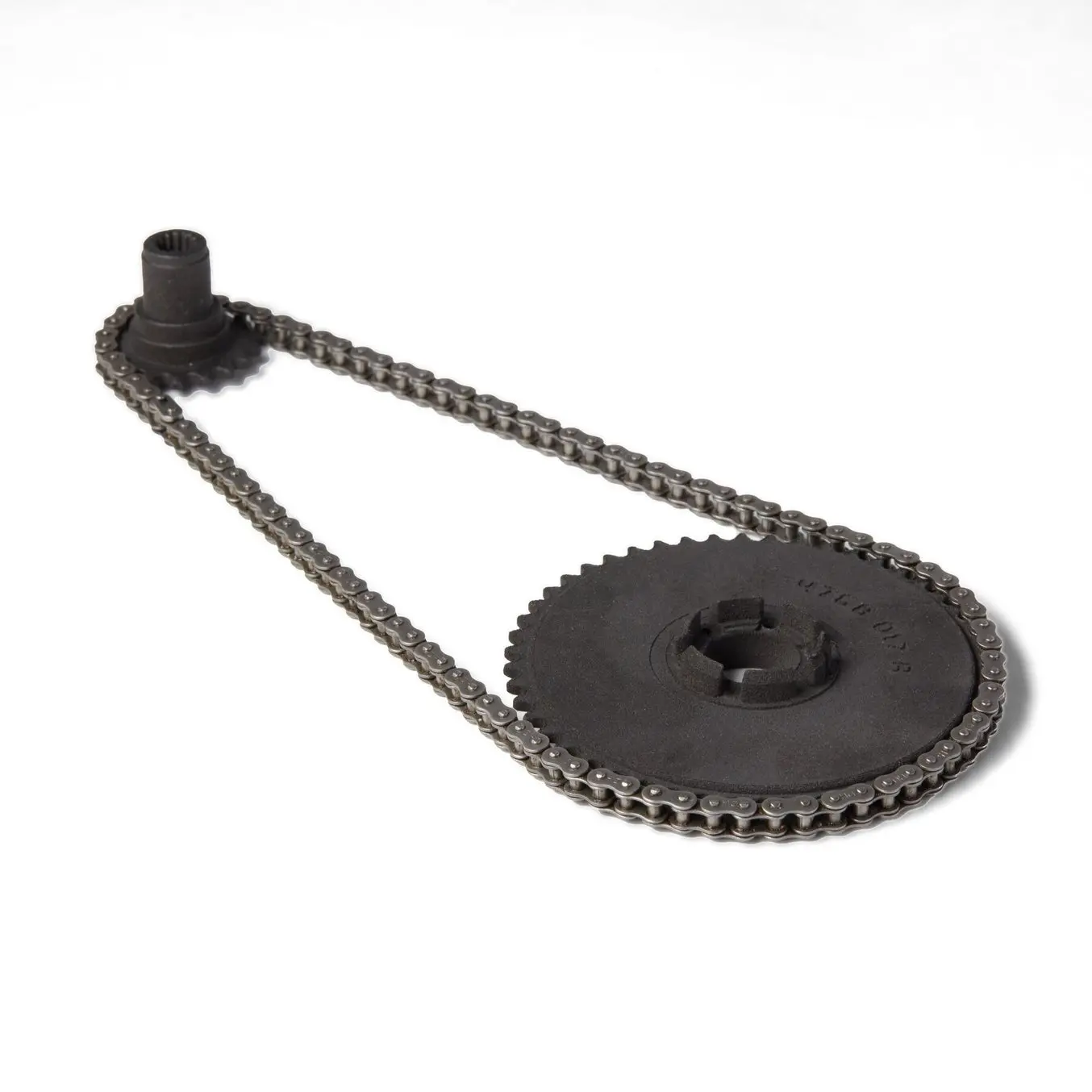
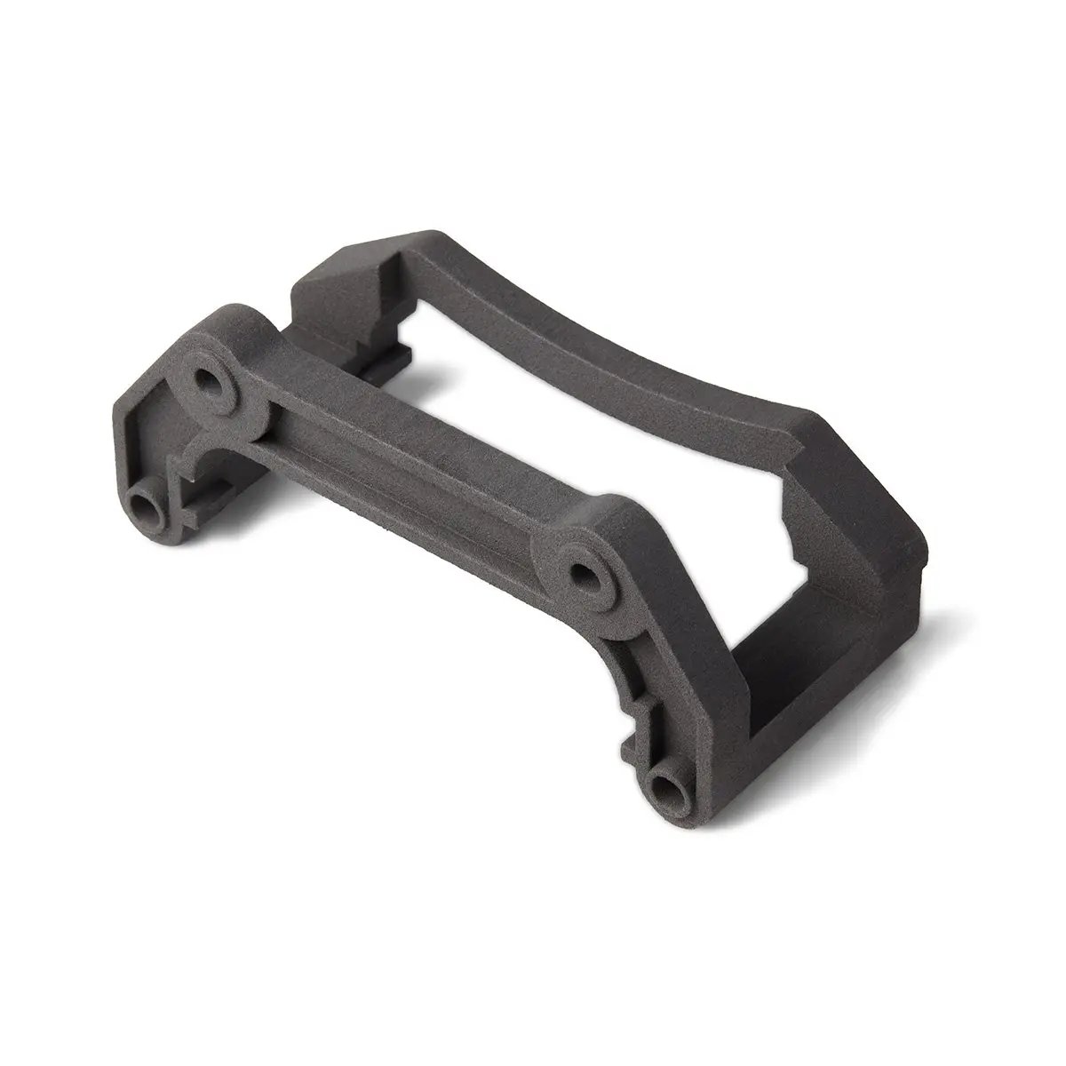
Formlabs Nylon 11 CF Powder is strong, lightweight, and heat resistant, making it ideal for automotive, aerospace, and manufacturing applications.
Request a Free Sample Part
See and feel Formlabs quality firsthand. We’ll ship a free sample part to your office.
Get Started With Carbon Fiber Manufacturing
Fiber-reinforced polymer manufacturing is an exciting, yet intricate and labor-intensive process. Using 3D printed molds and patterns to make carbon fiber parts allows businesses to reduce workflow complexity, expand flexibility and design opportunities, and reduce costs and lead time.
For directly 3D printed parts that offer many of the benefits of carbon fiber, with the additional advantages of geometric flexibility and a simpler and more efficient process, there are materials such as Formlabs Nylon 11 CF Powder for the Fuse Series SLS 3D printers.
To discuss your application and figure out the best approach for you to use 3D printing for carbon fiber parts, contact our team.