
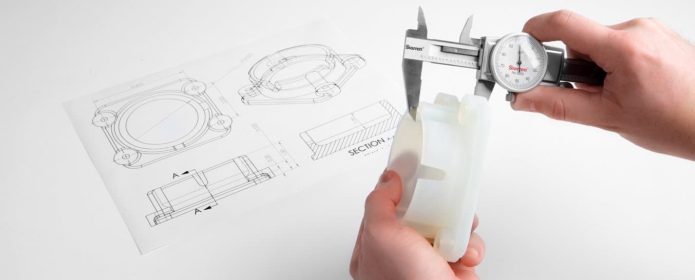
Just because a 3D printer has "high resolution” in the printer specifications doesn’t mean your 3D printed parts will be accurate or precise.
Understanding the meaning of accuracy, precision, and tolerance is imperative for achieving meaningful 3D print performance for any application. In this post, we’ll parse through what these terms mean and how to think about them in the context of 3D printing. Then, we'll compare the tolerance ranges you can expect from different 3D printing processes and provide a detailed overview for tolerancing 3D printed assemblies.
To learn more about specific print results, see in-depth accuracy studies on Formlabs Form Series SLA 3D printers and Fuse Series SLS 3D printers.
Defining Accuracy, Precision, and Tolerance
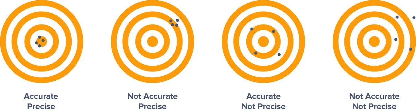
Let’s start with definitions: What’s the difference between accuracy, precision, and tolerance? For each term, we’ll use a target — a common example for unpacking these concepts — to help visualize meaning.
Accuracy
Accuracy is how close a measurement is to true value. In the case of a target, true value is the bullseye. The closer you are to hitting the bullseye, the more accurate your shot. In the world of 3D printing, true value equals the dimensions you design in CAD. How closely does the 3D print line up to the digital design?
Precision
Precision measures the repeatability of a measurement — how consistent are your shots at the target? Precision measures this consistency only; your shots could be hitting near the same spot every time, but that spot doesn’t have to be the bullseye. In 3D printing, this ultimately translates to reliability; can you rely on your machine to produce your expected results for every print?
Tolerance
Exactly how precise do you need to be? That’s defined by tolerance, and tolerance is defined by you. How much wiggle room do you have in your application? What’s an acceptable variance in the closeness to the measurement that precision is hitting? That will depend on your project, for example, a component with a dynamic mechanical assembly will require tighter tolerances than something like a simple plastic enclosure.
If you’re defining a tolerance, you’ll likely want accuracy too, so let’s assume we’re measuring precision of shooting at the bullseye. Earlier, we defined the shots on the target pictured on the right as not precise.

However, if your tolerance range is fairly wide, it may be okay. The shots aren’t as close to each other as in the target on the left, but if the acceptable range of precision is the distance of ±2.5 rings, then you’re within spec.
Generally, achieving and holding tighter tolerances means higher manufacturing costs and quality assurance.
Book a Free Consultation
Get in touch with our 3D printing experts for a 1:1 consultation to find the right solution for your business, receive ROI analyses, test prints, and more.
Achieving Tight Tolerance with Robust Engineering Materials
Watch our webinar for a walk through the SLA 3D printing workflow, material options, and expert tips to optimize the part-to-print workflow to get the most value out of 3D printing.
What Impacts 3D Printing Tolerances, Accuracy, and Precision
There are a variety of factors to consider when thinking about accuracy and precision in 3D printing. Knowing that the printer will consistently work as promised and produce the quality expected from it, within the tolerances the user is used to, could be crucial to a successful experience.
Here are four big factors at play in determining the accuracy and precision of 3D printing:
3D Printing Technology
3D printing is an additive process, so parts are built layer by layer. Each layer introduces an opportunity for inaccuracy, and the process by which layers are formed affects the level of precision, or repeatability, of the accuracy of each layer. Let's look at the typical 3D printer tolerances for the most common plastic 3D printing processes:
- Stereolithography (SLA) and digital light processing (DLP): ±0.15% for features 1–30 mm, ±0.2% for features 31–80 mm, and ±0.3% for features 81–150 mm, with a minimum lower limit of ±0.02 mm
- In resin 3D printing, liquid resin material is selectively exposed to a light source to form very thin solid layers of plastic that stack up to create a solid object. Thanks to the highly-precise light sources, these processes can achieve fine details and can consistently produce high quality results. Depending on the model geometry, resin 3D printed parts require support structures, which can be essential to achieve dimensional accuracy, especially with complex geometries or large and thin walls.
- Selective laser sintering (SLS) and multi jet fusion (MJF): +/- 0.5% or 0.3 mm, whichever is larger
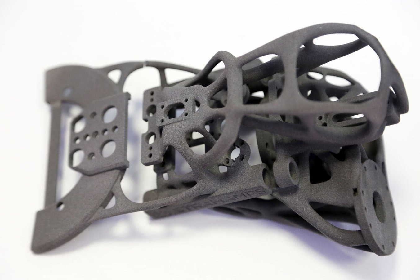
- Powder bed fusion 3D printers also rely on the precision of a light source — SLS a laser, MJF a fusing lamp — to fuse powder materials into solid parts. As the unfused powder supports the part during printing, there’s no need for dedicated support structures. This makes SLS ideal for complex geometries, including interior features, undercuts, thin walls, and negative features.
- Fused deposition modeling (FDM): ± 0.5% (lower limit: ± 0.5 mm)
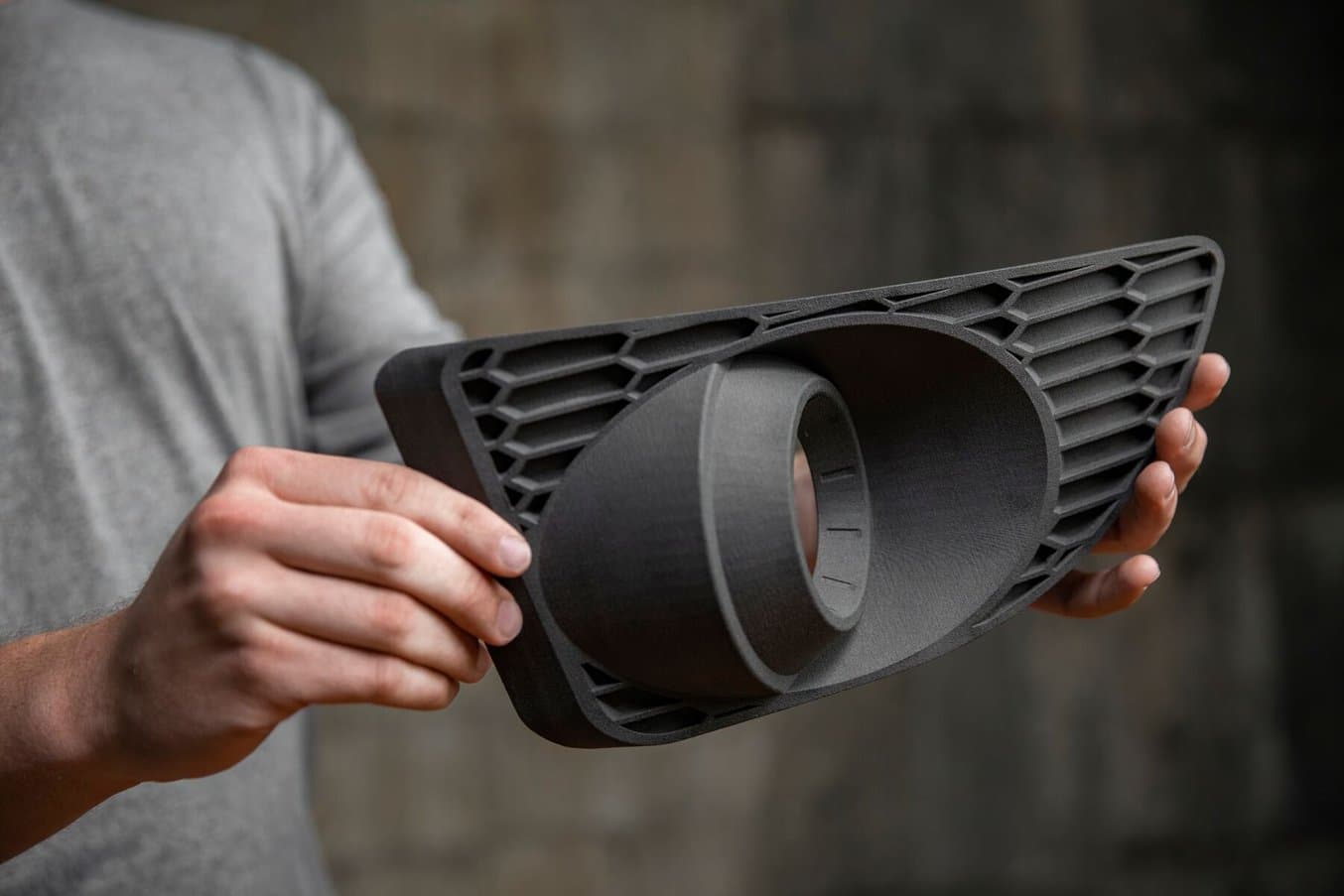
- In FDM 3D printing, layers of thermoplastic filaments are extruded by a nozzle, which lacks the control and ability to achieve intricate details that other 3D printing processes can offer. FDM parts are also prone to warping or shrinkage, as the printed part cools at different rates and the internal stress cause the print to deform. Higher-end professional systems mitigate these issues, but they also come at a higher cost.
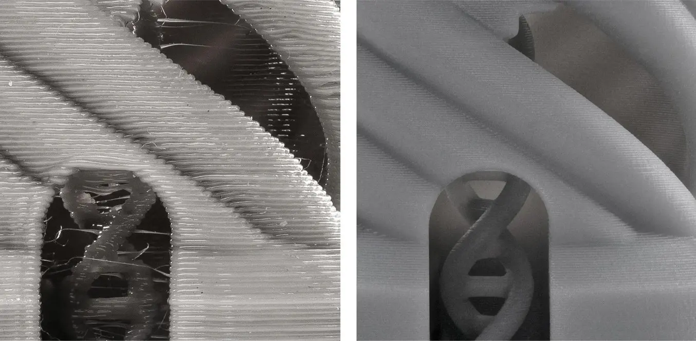
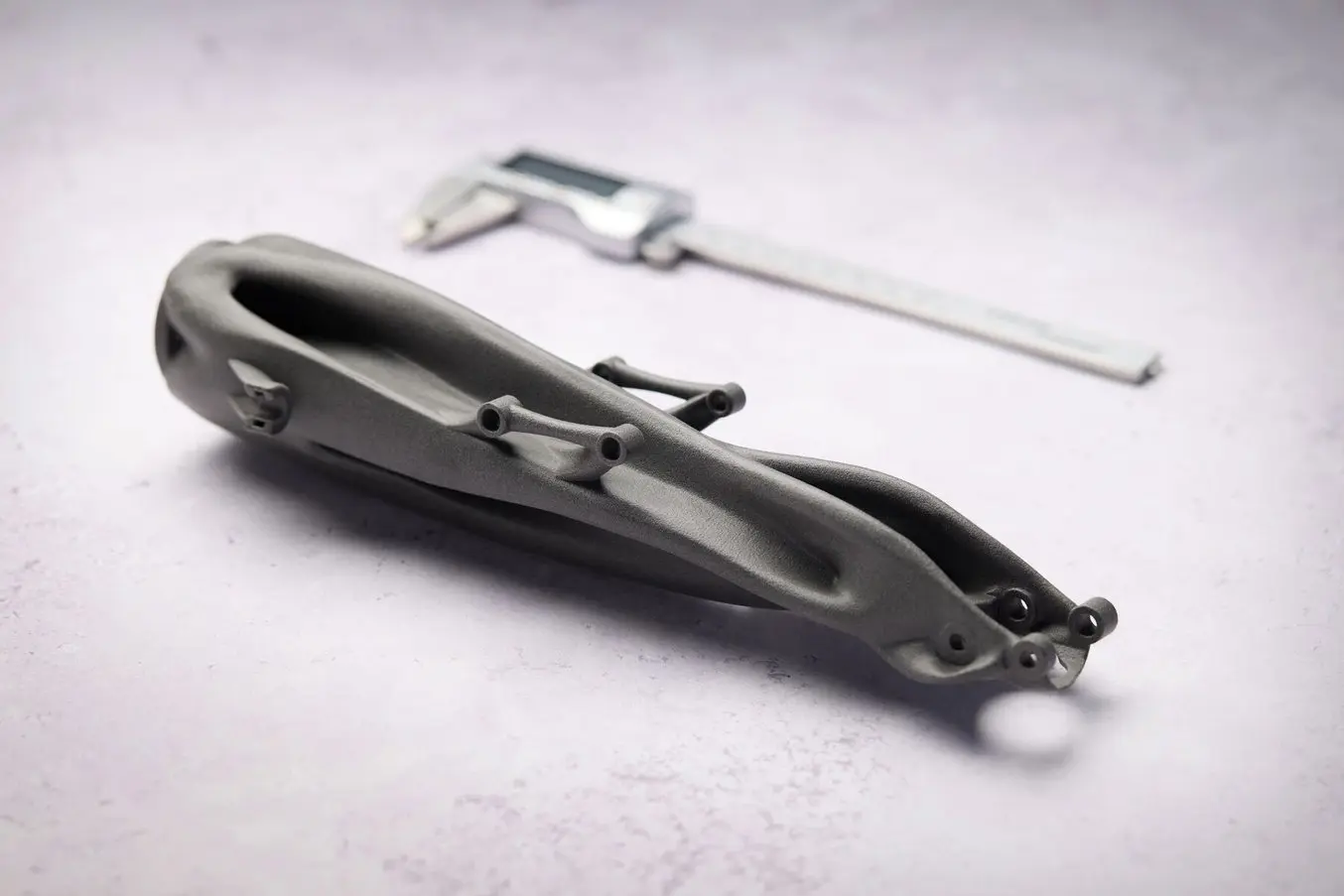
Because layers are extruded, FDM parts might show inaccuracies around complex features. (FDM part on the left, SLA part on the right).
3D printer specs alone do not represent final dimensional accuracy. One common misrepresentation of accuracy for various 3D printing technologies is the descriptions of XY resolution or Z resolution (layer thickness) as dimensional accuracy.
However, this data has no implications for how accurate a printed part will be. There are many sources of error that still have an impact on accuracy, which we'll cover next.
Ultimately, the best way to evaluate a 3D printer is to inspect real parts.

Request a Free Sample Part
See and feel Formlabs quality firsthand. We’ll ship a free sample part to your office.
Materials
Accuracy may also vary depending on which materials you use to print, and the mechanical properties of those materials, which can also affect how likely a print is to warp.
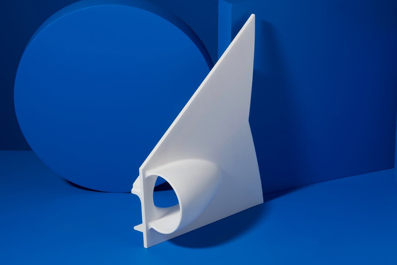
Formlabs Rigid 10K Resin for SLA 3D printing has high green modulus, or stiffness, which enables successful printing of thin, intricate features.
Due to the lack of support structures and great mechnical properties, Nylon Powders used in SLS 3D printing are also ideal for printing complex parts with demanding tolerance requirements.
With resin 3D printers, when a material has a high green modulus (modulus before post-curing), that means it’s possible to print very thin parts with precision and a lower chance of failure.
For FDM 3D printers, materials extruded at higher tempetatures are generally more prone to warping than others. For example, ABS is known to be more susceptible to warping than PLA as the printed parts shrink more during cooldown.
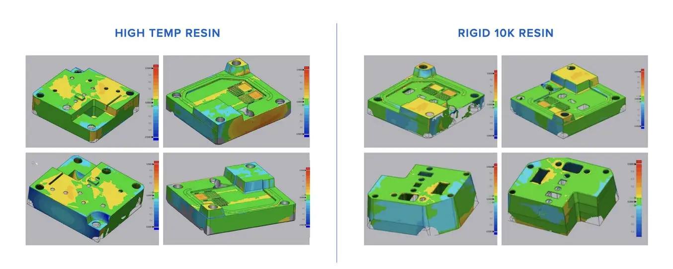
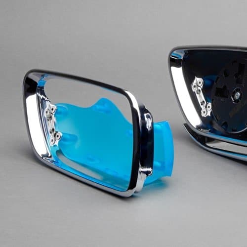
Scans of molds printed for a technical study on injection molding with 3D printed molds. These scans show a variation smaller than ±0.05 mm for more than 75% of the part.
Post-Processing
Most 3D printed parts require some form of post-processing after printing:
- SLA and DLP: Washing, post-curing (optional), removal of support structures (if needed), sanding (optional)
- SLS and MJF: Removal of excess powder, media blasting or media tumbling
- FDM: Removal of support structures (if needed), sanding (optional)
Some of these post-processing steps have an influence on the dimensions and the surface of the parts, which in turn influence accuracy and tolerances. Some of these are easy to account for during design and print preparation, but others can vary print to print.
For example, in resin 3D printing, parts often need to be post-cured after 3D printing, and post-curing causes shrinkage. This is normal for any parts produced with resin-based SLA or DLP 3D printing processes, and may need to be considered in designs depending on the printer. PreForm, Formlabs’ free print file preparation software, automatically compensates for this shrinkage to ensure post-cured prints are dimensionally accurate to the original CAD designs.
On the other hand, FDM printed parts often require sanding to improve the surface quality by removing support marks and layer lines, but this process changes the dimensions of the parts slightly, increasing the variation between the original design and the finished part.
Ecosystem and Calibration
Producing accurate and precise 3D prints requires attention to more than the printer itself, and consideration for the entire process.
The print preparation software, printing technology, quality and calibration of the printer and its components, quality of 3D printing materials, and post-processing tools and methods can all contribute to final results.
Overall, integrated systems that are designed to work together generally produce more reliable results. For example, each new SLA and SLS 3D printing material from Formlabs goes through a series of validation tests on each compatible printer model before release to ensure reliability, consistency, and accuracy. That's not to say that generic printers and off the shelf materials can't produce good results — they might just have a steeper learning curve and require more experimentation and calibration from the users.
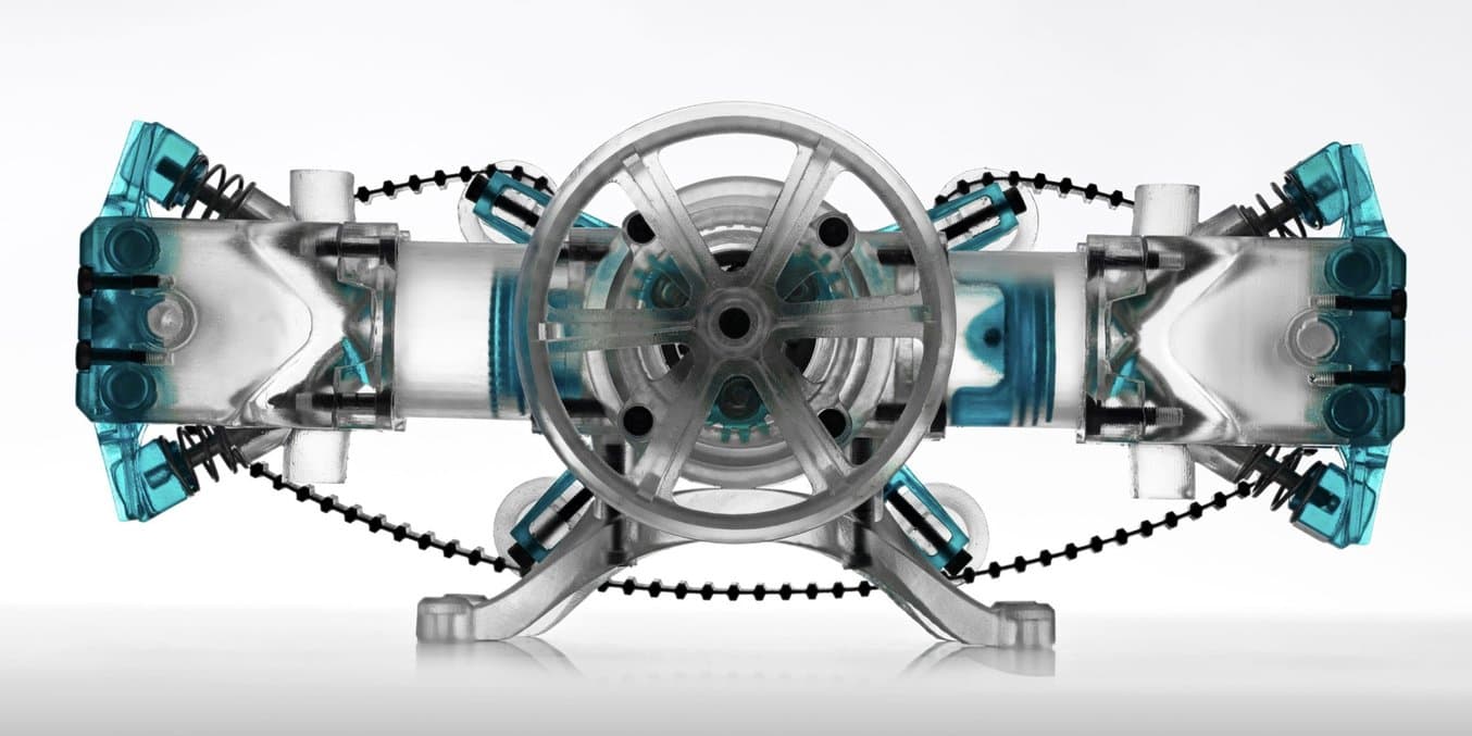
An air-powered, functional scale model of a flat two-cylinder internal combustion engine printed in Formlabs resins and lubricated with mineral oil.
Tolerancing in 3D Printing
In traditional machining, tighter tolerances are exponentially related to increased cost. Tighter tolerances require additional and slower machining steps than wider tolerances, so machined parts are designed with the widest tolerances allowable for a given application.
Unlike machining, 3D printing has a single automated production step. Tighter 3D printing tolerances may require more effort in the design stage, but can yield significant savings in time and costs in prototyping and production.
Also, while complex surfacing adds costs to a process like CNC milling, complexity in 3D printing is essentially free, though the tolerances of a 3D printed part can't be automatically refined beyond what the printer can produce without resorting to subtractive methods. 3D printing is great option if you have gross complexity like undercuts and complex surfaces, and don't necessarily need higher surface precision than ±0.005 in (standard machining). Tolerances beyond standard machining have to be reached subtractively, either through hand finishing or machining, in both 3D printed parts and CNC parts.
Overall, resin 3D printing (SLA and DLP) and powder bed fusion 3D printing (SLS and MJF) have the highest tolerance of commercially available plastic 3D printing technologies. Compared to machined accuracy, resin and powder 3D printing tolerance is somewhere between standard machining and fine machining.
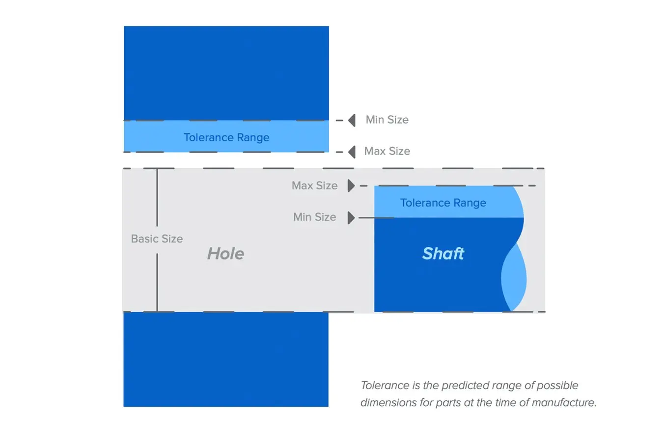
Tolerance is the predicted range of possible dimensions for parts at the time of manufacture.
Form 4 Series Design Guide
A successful 3D print starts with a well-designed model. Follow our best practices to optimize designs and reduce failures.
Fuse Series Design Guide
In this design guide, you’ll learn about some of the important considerations for designing for SLS 3D printing on the Fuse Series, and how you can leverage these practices to create successful parts.
Tolerancing for 3D Printed Large Assemblies and Small Scale Manufacturing
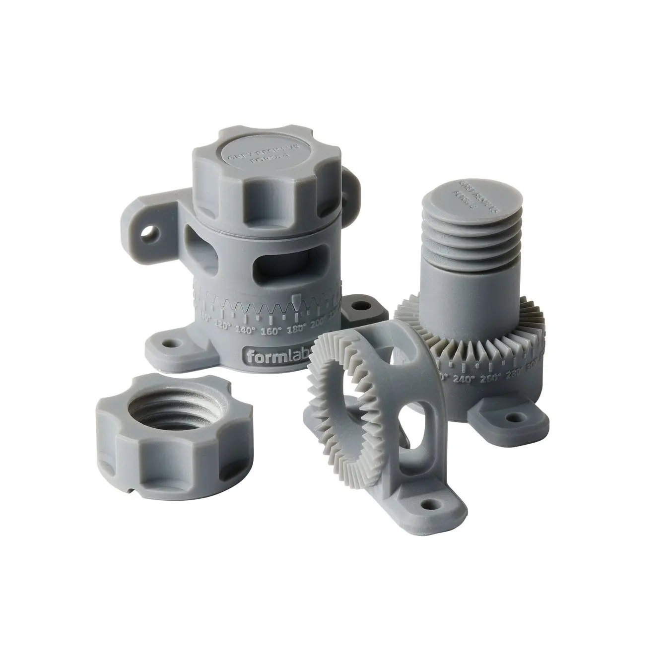
Tolerance and fit are essential concepts for any engineer designing mechanical assemblies. Accounting for tolerances ultimately optimizes both the prototyping and production processes, reducing the material cost of iteration, lowering post-processing time, and mitigating the risk of accidentally broken parts. The static cost-per-part for 3D printing makes it a cost-effective method for prototyping and low volume manufacturing, especially for custom parts that would otherwise require significant investment in molds.
Generally, more compliant 3D printing materials will have a wider tolerance zone than more rigid materials. When printing parts for assemblies specifically, designing for proper tolerance and fit lowers post-processing time and ease of assembly, and reduces the material cost of iteration.
Post-processing steps for 3D printed parts assemblies commonly include cleaning, sanding supports, and lubrication. Sanding an active surface is a reasonable method for achieving the correct fit if the part is a one-off, because less tolerancing work is required in the design phase. With larger assemblies, or when producing multiples of something, proper dimensional tolerancing quickly becomes worthwhile.
In this section we’ll walk through the different engineering fits to describe the basics of clearance, transition, and interference fits and when it makes sense to choose each for an assembly design.
Choosing the Best Type of Engineering Fit
In order to understand and design the optimal 3D printing tolerances, it’s important to determine which type of fit works best for your assembly.
The functional needs of your assembly define how parts should fit together.
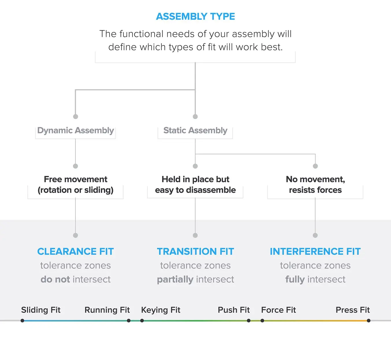
Engineering fit can be divided into three types: clearance, transition, and interference. Each of the these types of fit can then be broken down into two major subcategories.
There will always be some variation in tolerances for different manufacturing methods and depending on the 3D printing process, which means that fit is a continuum rather than completely separate stages. For example, larger clearance fits trade precision for freedom of movement. Tighter transition fits are stronger, but cause more wear on the connection. An interference fit that requires more force to join will be more challenging to disassemble.
Clearance Fit
Free movement of a component requires clearance, or space between the active surfaces. Achieve clearance by ensuring that the tolerance zones of the active surfaces do not overlap.
An active surface is a model region where two surfaces touch and either move against each other or have a static fit.
Subcategories:
- A sliding fit has some lateral play, while a running fit has almost no play.
- A running fit has slightly more friction, but more accurate motion.
Play is the amount of space for movement in an unintended direction within a mechanism.
Transition Fit
If no motion between parts is needed, a transition fit allows for easy assembly and disassembly. A transition fit has partially overlapping tolerance zones.
Subcategories:
- With a keying fit, a component accurately inserts into or around another part, with only a light force needed to install and remove it.
- A push fit requires more force to join and remove the parts, but they can be connected by hand.
Interference Fit
An interference fit provides a rigid, strong connection, but requires much more force applied in assembly. Tolerance zones fully intersect in interference fits.
Subcategories:
- A force fit requires substantial force to install, likely with additional hand tools like a hammer, and is intended to be permanently joined.
- A press fit needs much more force to install, applied by an arbor press or similar tool.
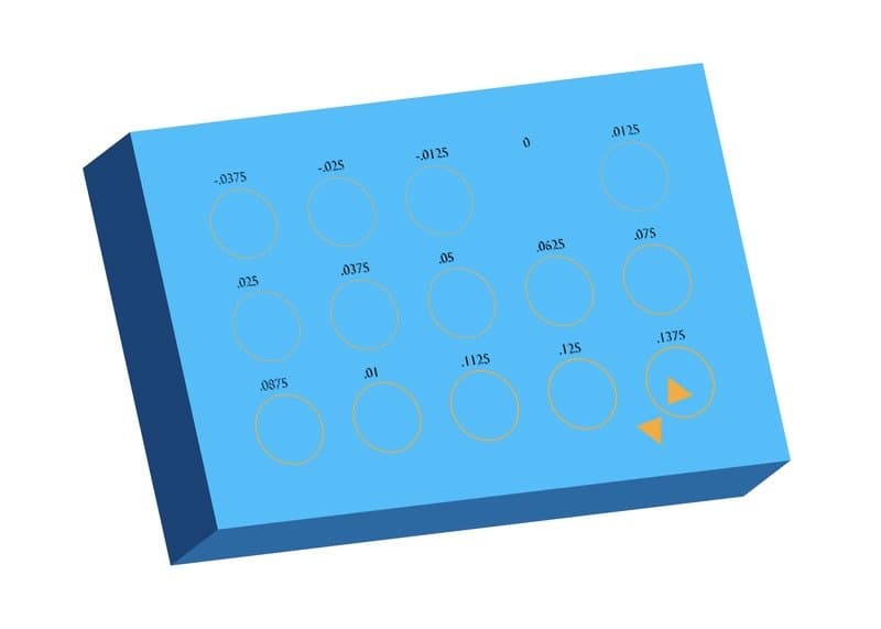
Measuring and Applying Tolerance
To find the real-life tolerance needs of each kind of fit, it is helpful to examine a variety of common geometries including the following.
Hole and Shaft
A hole and shaft will usually require a clearance condition, which may range from a sliding fit to a running fit depending on needed accuracy. A running fit will require sufficient lubrication for free movement.
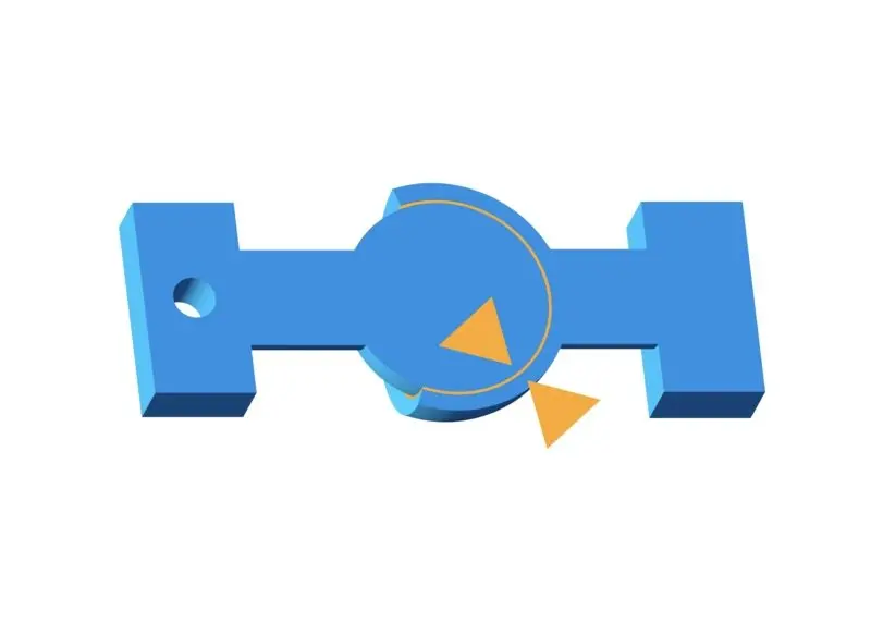
Ball and Socket
A clearance condition should exist to allow the ball to rotate freely in the socket. However, there is a large interference between the radius of the ball and the socket opening. The socket opening needs to deform enough to be inserted, but not come out in normal use.
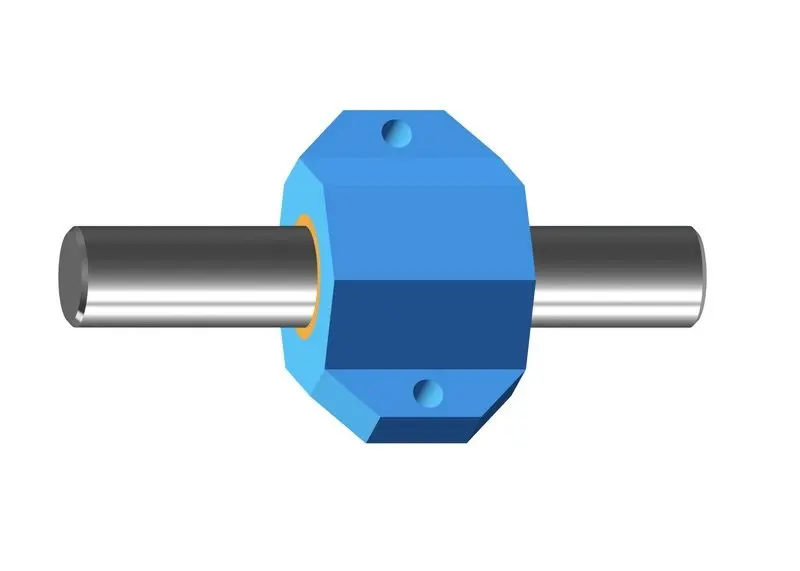
Rod and Bushing
A bushing is a type of plain bearing designed for smooth, free movement along a rod. There should be a clearance fit between the rod and the bushing. Depending on the application, the clearance may be larger or smaller.
Friction
The amount of friction force between two components is the product of the force on the mating surface (directly related to fit), and a constant (the coefficient of friction), which is specific to each material. Coefficient of friction is useful for predicting how much resistance your parts will have to movement and wear, and how you can expect Formlabs resins to perform relative to other common materials.

Formlabs tests the coefficient of friction using a weighted sled, a track, and a force meter.
High lubricity, such as that of Tough 1000 Resin, will have lower sliding friction. A lower coefficient of friction makes it better suited for moving components which interact in kinetic assemblies.
Sliding components such as rails, pistons, and rods have lower friction if the contact surface area of the two mating surfaces is reduced. This is achieved by orienting objects in PreForm so that the layer “grain” pattern is perpendicular between the parts. If the grain is parallel the layer grooves will mesh, creating more surface area and higher static and kinetic friction.
A micro-scale diagram of friction between surface orientations

Left: Most static and kinetic friction. Middle: High static and moderate kinetic friction. Right: Least static and kinetic friciton.
In both the static and kinetic tests, the perpendicular orientation had lower frictional coefficients. The coefficient of static friction is impacted more significantly by grain orientation. Friction between parts decreases over time as the surfaces experience wear. This is often beneficial to kinetic assemblies, and sanding and polishing is a deliberate example of wear. However, excessive wear tends to increase clearances between parts. Lubrication is the best way to reduce long term wear.
In some cases — such as rollers, wheels, and robotic grippers — more friction is beneficial. For these applications, select a material with a higher coefficient of friction and lower lubricity.
Lubrication
Lubricants are essential to keeping components running smoothly in kinetic assemblies. Mineral oil is an inexpensive and commonly available lubricant commonly used with SLA prints. Silicone oil based lubricants, such as Super Lube®, also work well, and last longer without becoming sticky.
Bonded Components
In order to bond printed components with adhesives, a narrow clearance fit is desired. Cyanoacrylate (Super Glue) will fill thin gaps due to its low viscosity. A syringe of resin cured by hand with a UV or blue-violet (405 nm) laser pen (and UV safety goggles) can be used to weld parts together in butt joints.
Machining Printed Parts
The most common post-processing steps for printed assemblies are sanding, polishing, and lubricating. Occasionally it can be useful to machine a plastic part after printing, for example, if the tolerances of a feature need to be tighter than 0.025 mm, or to alter a feature after printing.
Adding holes with a drill press or threads with a tap can be faster and more efficient than re-printing if the tools are available and the design has changed in the middle of a print. Tough Resins – including Tough 1000 Resin, Tough 1500 Resin, and Tough 2000 Resin – withstand machining the best of Formlabs range of materials due to their high strength and elongation. Other Formlabs Resins can also be machined, though they require more conservative techniques and faster tool speeds.
Find the 3D Printing Material for Your Application
Specifying fit based on material properties and mechanical function is a necessary practice in product engineering. The fit ranges shown for common geometries can be broadly applied to many designs to achieve functional prototypes with fewer iterations. For even more accuracy and an intuitive understanding of how parts will fit together, print the test models in a wider variety of materials and see how they perform.
There are tons of other attributes to consider when evaluating 3D printers. Do your parts need to be isotropic? What mechanical properties are required? Choosing the right material is essential for creating working prints and Formlabs materials vary significantly in tensile strength, elongation, and wear resistance.
Use the Formlabs material comparision page to find the best material for your application or request a free sample part to evaluate the quality for yourself.