Creating a new layer thickness with the Print Settings Editor (SLA)
Creating a new layer thickness with the Print Settings Editor (SLA)
There are many reasons that changing a print’s layer thickness can be useful, whether for higher print speed, finer features, or for smoother surfaces. Formlabs typically tunes print settings for 100 μm and 50 μm layer thicknesses, since these meet most common user needs, but your specific application may require something else. Creating a new layer thickness is also one of the simplest ways to begin learning how to utilize the Print Settings Editor for tuning Formlabs materials to best suit your needs.
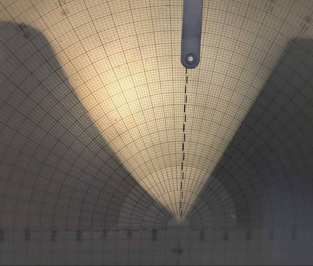
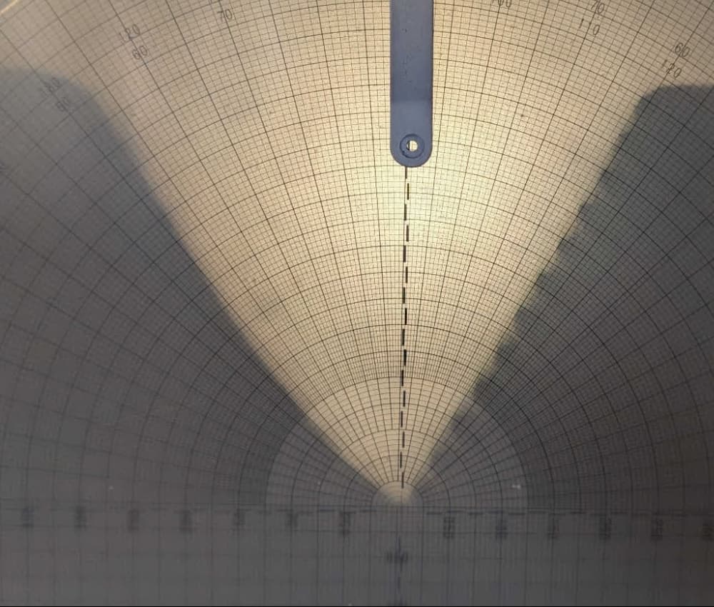
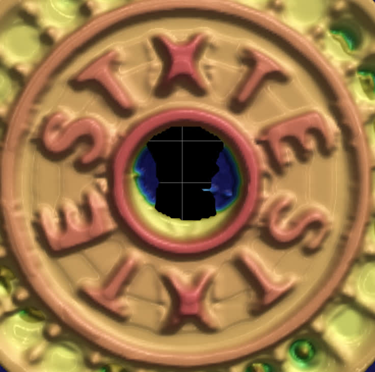
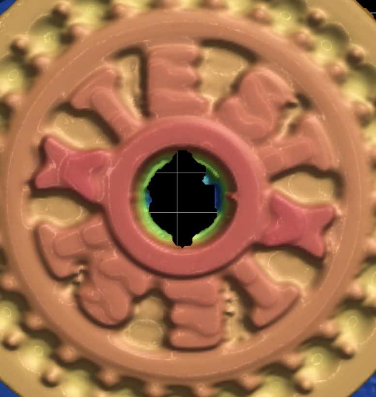
Above are two magnified images of screw threads printed at different layer thicknesses. The part on the left was printed at 25 microns, while the part on the right was printed at 100 microns. The difference in the top surface can be clearly seen, with some stairstepping evident at 100 microns, but note that the other surfaces and general accuracy are not dramatically different between the two. While lower layer thicknesses will always increase your print time, they will not necessarily increase the accuracy of your prints.
Creating a custom print setting
Follow the instructions for creating a custom print setting in Using the PreForm Print Settings Editor (SLA). Start with a Formlabs print setting for your material and choose a layer thickness as close to the desired layer thickness as possible. For example, start with a 100 micron print setting if you are planning to create a 200 micron setting, or choose the 50 micron setting for a 25 micron setting. This will reduce the amount of tuning necessary. Make sure to name the print setting and give it a description so you can easily find and use it in the future.
Settings that impact layer thickness
When changing the layer thickness of a custom print setting, you will often also need to change the following parameters. For a full explanation of each parameter, see Using the PreForm Print Settings Editor (SLA).
| Parameter | Notes |
|---|---|
| Layer Thickness | Changing this parameter only changes the motor moves between layers. No other values, such as exposure or backlight intensity, are recalculated. |
| Model Fill Exposure | Model Fill Exposure defines the energy density applied while printing the interior of each model. Since you are changing the thickness of resin that needs to be cured with each layer, you also need to change this value to compensate. Generally, this scales linearly with thickness. For example, for a layer thickness half of the original print setting, apply half the exposure. |
| Supports Fill Exposure | Same as Model Fill Exposure |
| Perimeter Fill Exposure | Same as Model Fill Exposure |
| Overhang Fill Exposure | Same as Model Fill Exposure |
Less commonly, you may also need to modify these parameters:
| Parameter | Notes |
|---|---|
| Post Exposure Cure Wait | Increasing Post Exposure Cure Wait can let the part relax away from the tank film more easily and lower the forces experienced by your parts during printing. |
| Irradiance | Irradiance, or LED intensity, can be increased to reduce print time. Decrease this value to improve print reliability, extend LPU lifetime, and mitigate resin gelling. |
| Squish Intensity | Smaller layer thicknesses can require more gentle squish moves to prevent damaging the part. Lowering Squish Intensity can improve this, though the printer should also compensate automatically. |
| Custom Squish | If Custom Squish is enabled, the constituent moves (Squish Deceleration, Max Squish Speed, Squish Wait, and Early Layer Squish Wait) will need to be tuned. For smaller layer thicknesses:
|
Tuning the settings
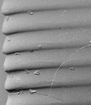
After first creating your custom print setting, run a test print with some geometries that are representative of what you are trying to print. If possible, start with parts that are printed directly on the build platform, since that avoids many issues that may be related to supports. Tune your print setting based on your results. Most errors can be addressed through changes to a few key parameters:
| |
| |
|  |
| |
|  |
|  |
Tutorials
Example 1: Creating a 150 μm layer thickness for ESD Resin
Creating a 150 μm layer thickness for ESD Resin is useful to speed up print times, especially when the parts are fairly simple geometric shapes. To get started, the following parameters were changed from the existing 100 micron print setting:
- Layer Thickness: 0.100 mm -> 0.150 mm
- Top Surface Exposure: 31.4 mJ/cm2 -> 47.10 mJ/cm2
- Supports Touchpoint Exposure: 31.4 mJ/cm2 -> 47.10 mJ/cm2
- Supports Fill Exposure: 41.3 mJ/cm2 -> 61.95 mJ/cm2
- Model Fill Exposure: 31.4 mJ/cm2 -> 47.10 mJ/cm2
- Early Layer Exposure and Offset:
- Entry 1: 133.4 mJ/cm2 -> 200 mJ/cm2
- Entry 2: 31.4 mJ/cm2 -> 47.10 mJ/cm2
Note that since the layer thickness has increased by 50%, the exposure parameters listed here have as well.
Initial test print
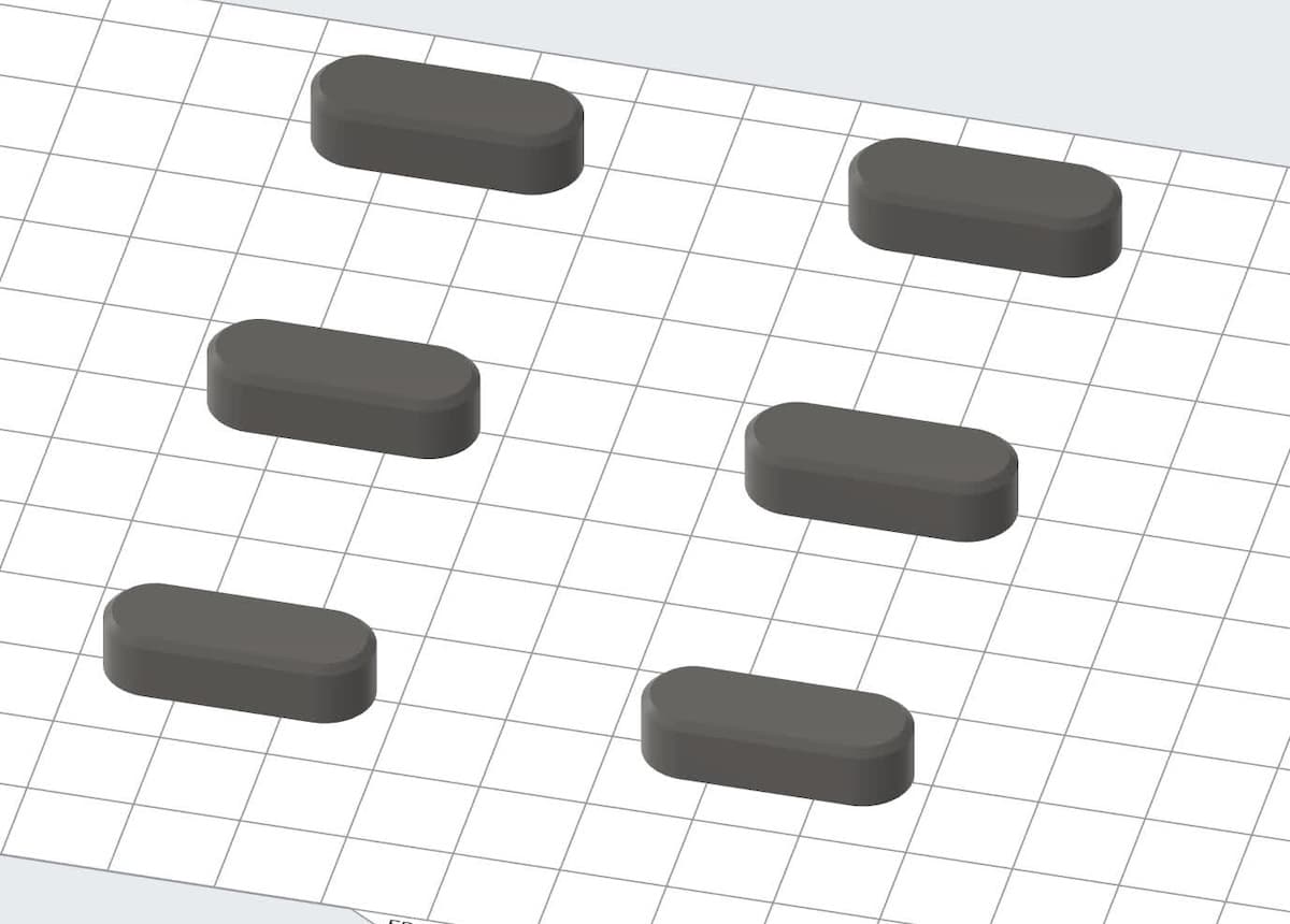
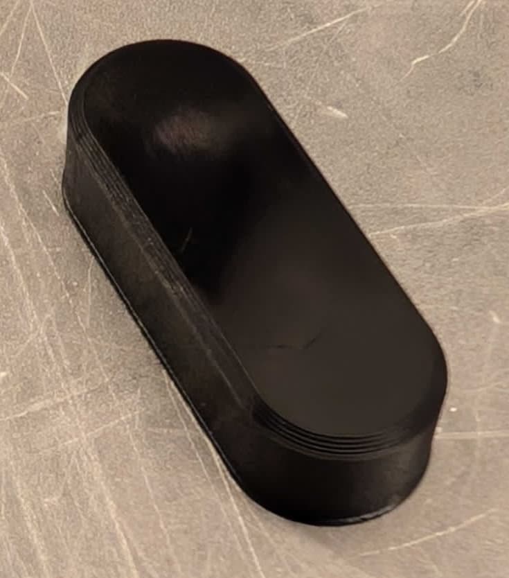
The initial test print was a set of locator clips for a watch. This model was chosen because it is small (42 layers and 16 minutes) and does not have undercuts, supports, or other features that may complicate tuning. This print had no issues, so the print setting is ready for more complicated testing.
Testing the new settings on a real part file
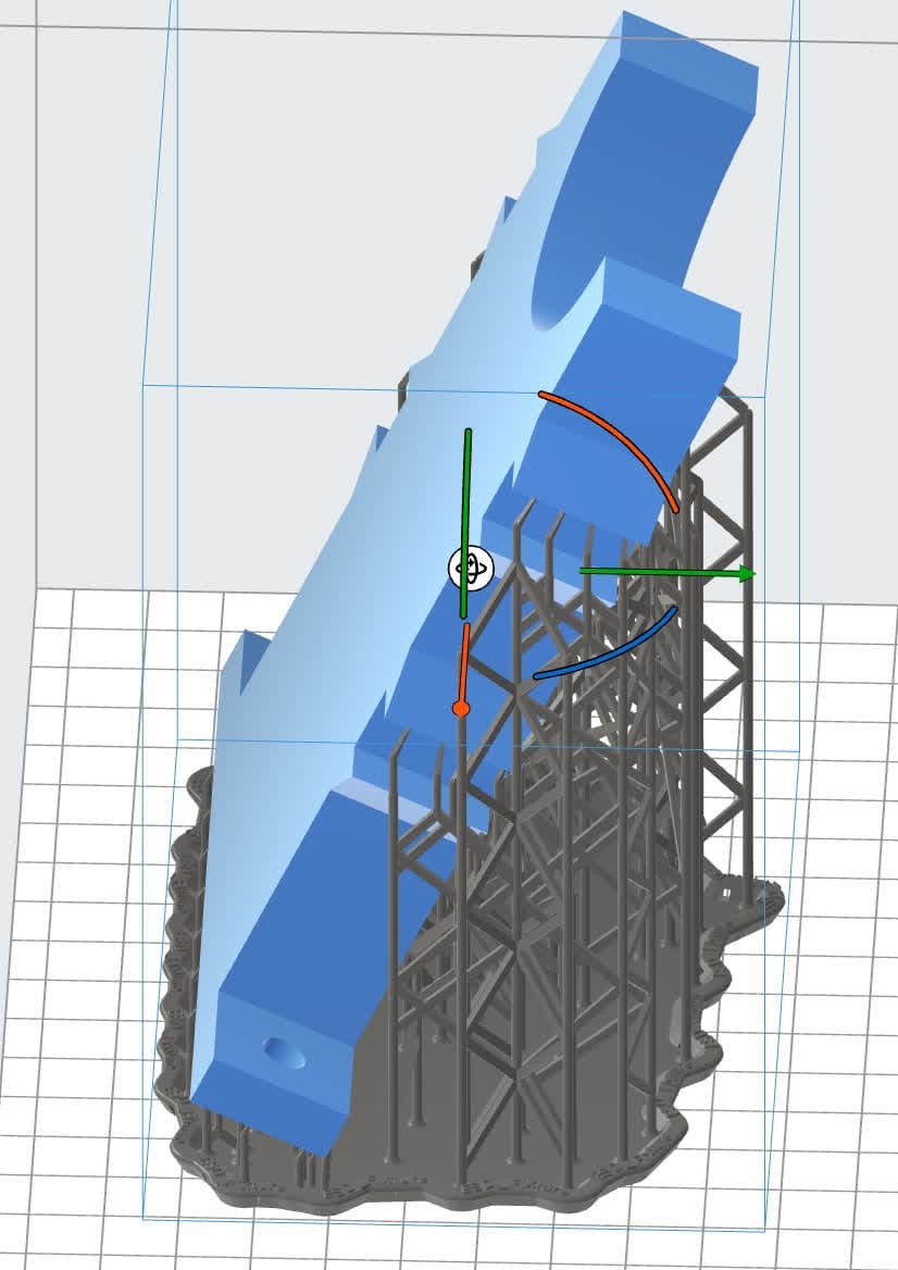
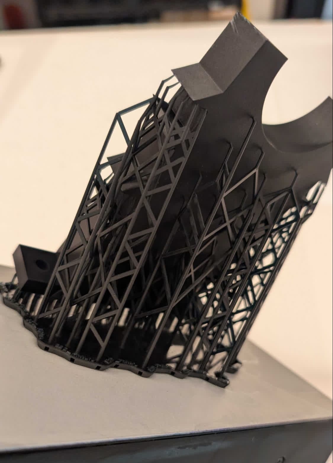
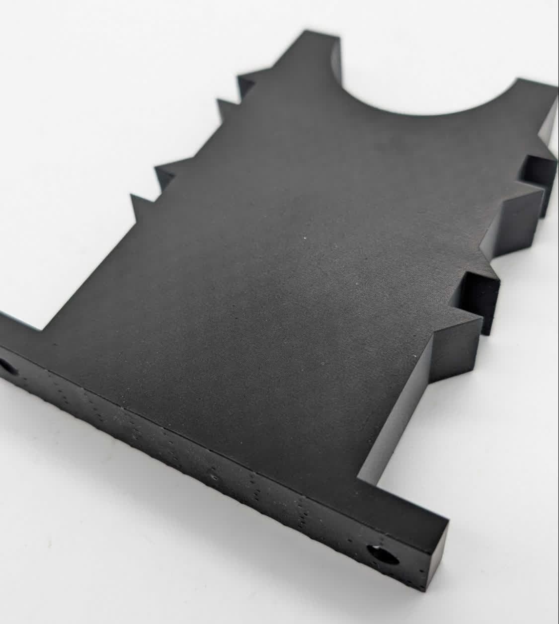
Developing print settings on a flat, simple test model is useful for solving initial problems and getting the new layer thickness to print, but your models may include features that can cause complications in the print, such as overhangs, large areas, supports, or fine features. After initially validating your custom print setting, continue to monitor more complex prints. In this example, we moved from a set of watch clips to a large bracket. This bracket requires supports and would generally take about five hours to print using standard 100 micron print settings. By increasing the layer thickness to 150 microns, we can reduce the print time to four hours. The bracket printed successfully with the parameters listed above. Note that significantly different models may require additional tuning.
Example 2: Creating a 10 μm layer thickness for ESD Resin
Extremely small layer thicknesses are generally not recommended. There are often much greater forces involved, which cause longer layer times and can risk damaging the resin tank or even the printer itself. The resolution gain is typically very minimal or even negative, since the smaller features are damaged either by the increased forces or by not being exposed as fully as they would be in a larger layer.
However, it is still possible to successfully print layers this small, so this example shows a 10 μm layer thickness, some associated failure modes, and parameters you can use to minimize risk.
To get started, the following parameters were changed from the existing 50 micron print setting. Note that since the layer thickness has decreased by 80%, the exposure parameters listed here have as well.
- Layer Thickness: 0.050 mm -> 0.010 mm
- All Exposure parameters: 18.4 mJ/cm2 -> 3.68 mJ/cm2
- Early Layer Exposure and Offset:
- Entry 1: 133.4 mJ/cm2 -> unchanged (0.0 mm)
- Entry 2: 18.4 mJ/cm2 -> 3.7 mJ/cm2 (0.6 mm)
- Heights and offsets unchanged
Since we have dramatically decreased the layer thickness, the squish parameters also need to be changed to much lower and more conservative values:
- Squish Deceleration: 500 mm/s2 -> 1.0 mm/s2
- At the default value, the build platform lowering into the resin would cause a massive increase in pressure, triggering a debris detection error on the printer.
- Early Layer Squish Wait: 110 s -> 120 s
- Squish Wait: 30 s -> 80 s
- For very small layer thicknesses, extra time is needed to allow all of the resin to squeeze out from underneath the part.
- Max Squish Speed: 60.0 mm/s -> 15.0 mm/s
- This also allows more time for the resin to get out of the way of the build platform and printed parts, decreasing the forces imparted on them and increasing overall print accuracy.
The initial test print
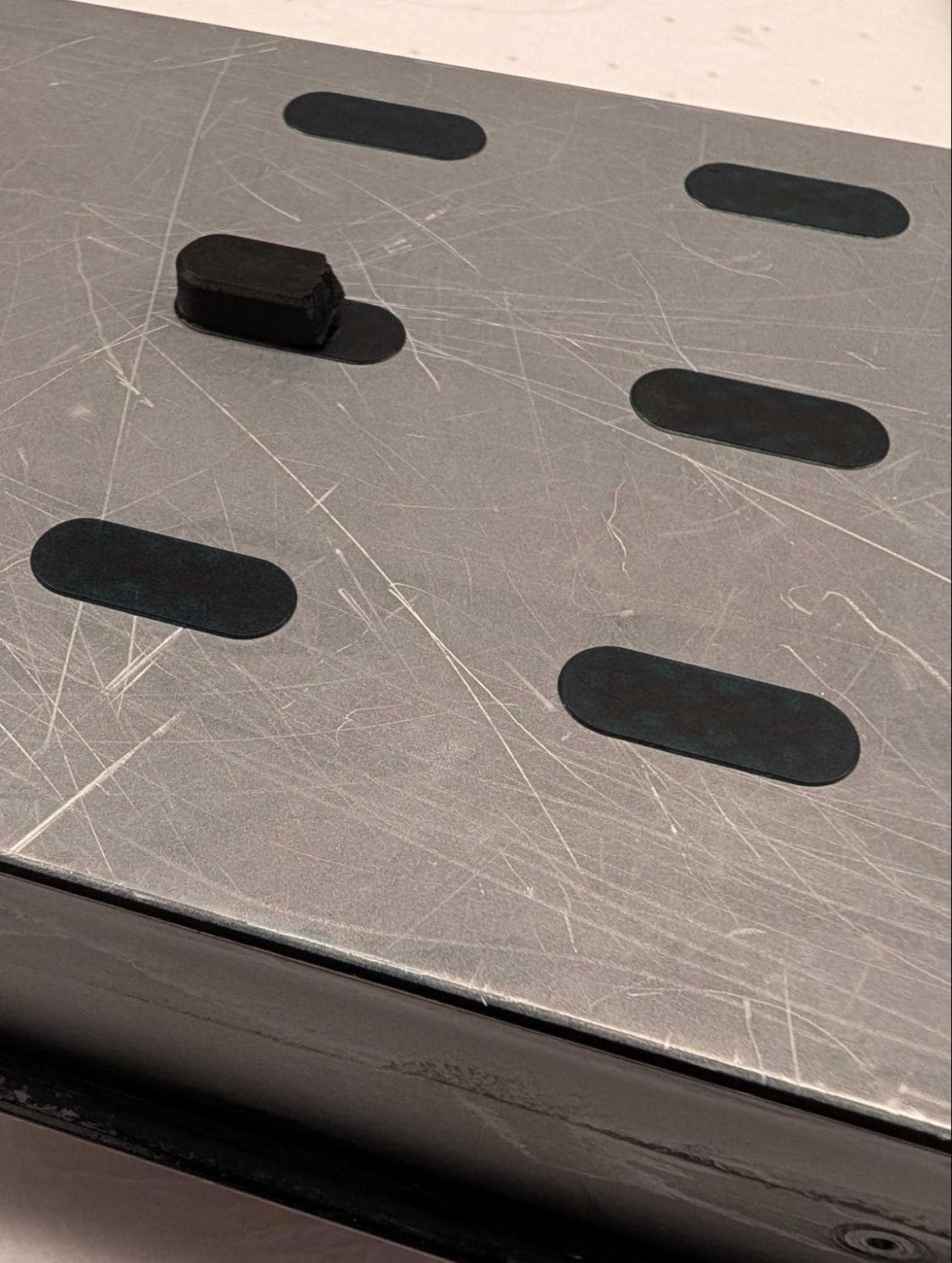
The initial test print was the same as for the 150 μm example above. Here, the print mostly failed, with all but one block failing after the initial layers.
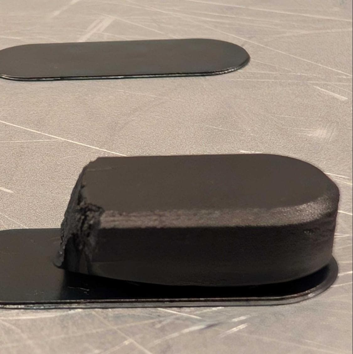
To troubleshoot this:
- Measure the thickness of the material that did succeed in adhering to the build platform. This helps to distinguish if there is an issue when transitioning from the early layer exposures (which end at 0.6 mm) or from transferring from the early layer squish.
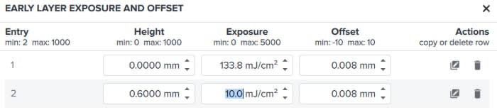
- Adjust early layer parameters in the Print Settings Editor based on your results. Here, the parts failed at almost exactly 0.6 mm, implying that the Exposure value at that height is too low. Previously in this example, we decreased the exposure in the second Early Layer Exposure and Offset entry from 18.4 mJ/cm2 to 3.7 mJ/cm2. Increasing it back to 10 mJ/cm2 worked to produce all six parts without an issue.
- Alternatively, increase the Height value. PreForm interpolates linearly between entries in the Early Layer Exposure and Offset array, so this would make the change in exposure more gradual between successive early layers.
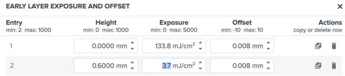
Early Layer Exposure and Offset array before first test print
Adjusted Early Layer Exposure and Offset array after first test print
Once the test parts printed successfully, more functional parts could be printed, taking advantage of the small layer thicknesses. For example, the part below is a fixture for holding delicate integrated circuits (ICs) in a small scale production line, which includes a 20 micron pad for the ICs to sit against and a locating feature in the center made of 10 micron steps.
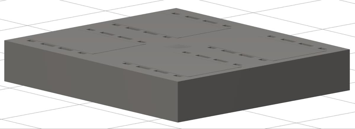
This part printed successfully, producing the fine vertical features mentioned above. Note that X/Y resolution did not improve with these lower layer thicknesses, so the features that are in the same plane as the build platform still need to be roughly the same tolerances and sizes as what would be needed at 50 microns.
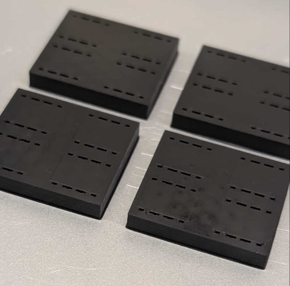
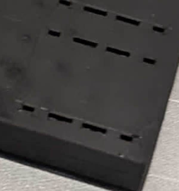
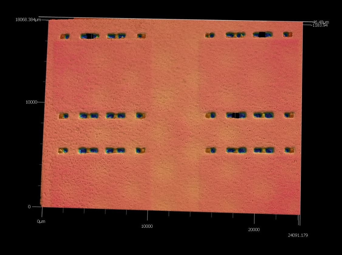
For a clearer view of the fine vertical features in this print, see the profilometer scan here. The 20 micron pads are shown as the darker red areas on the surface of the part. Note that the release texture from the Form 4 Light Processing Unit is also visible, shown as the lighter yellow dots across the surface. As the layer thickness is decreased further and further, this will become a greater portion of the layer.