
Required Supplies:
Formlabs:
- Motherboard
- 2.5 mm hex driver (included in the Form 4 tool caddy)
Third-party:
- 2 mm hex driver
- Nitrile gloves
- Anti-static grounding strap

The motherboard is the main electronics module on the Form 4 that controls the various subsystems. The motherboard attaches to the printer and is located behind the right side panel. A malfunctioning motherboard may prevent the printer from printing properly.
Use this guide to replace the motherboard.
Required Supplies:
Formlabs:
Third-party:
Estimated time: 2 hours
Notice:
This replacement guide exposes sensitive electronics within the Form 4. Static discharges can damage these electronics. Formlabs recommends using an anti-static grounding strap when performing this procedure.
Preparing the workspace
Overview: Prepare the printer and a dust-free workspace for replacing the motherboard.
Step 1: Remove the build platform
Remove the build platform first to avoid dripping resin onto the Light Processing Unit (LPU).
Step 2: Remove the resin cartridge
Remove the resin cartridge and close the vent cap to prevent resin from dripping off of the bite valve and into the printer.
Step 3: Remove and store the resin tank and mixer
Unlatch the mixer and resin tank. Remove the resin tank and cover it with its lid. Set the tank aside on a clean, flat surface.
Notice:
Wear gloves and hold the resin tank by the tank grips on either side to avoid contamination or damage to the underside of the tank.
Step 4: Prepare the workspace
Clear a workspace around your printer. Ensure that the workspace is well-ventilated and free of dust. Prepare additional space for storing the exterior panels, the LPU, the resin tank latches, the touchscreen, and the nest of the printer during maintenance.
Step 5: Clean the printer
Warning:
Resin may cause skin irritation or an allergic skin reaction. Wear gloves when handling liquid resin or resin-coated surfaces. Wash skin with plenty of soap and water.
Open the printer cover and clean any resin pooled on and around the LPU with non-abrasive wipes. Dampen the wipes with isopropyl alcohol if necessary to fully remove the resin.
Danger:
Fire hazard. IPA is flammable. Keep containers closed, and keep out of the reach of children.
Step 6: Unplug the printer
Disconnect the power cable before continuing with maintenance. Do not perform maintenance on the printer while it is connected to power. Wait five minutes after disconnecting the printer from power before proceeding.
Danger:
Performing maintenance on the printer while it is plugged in increases the risk of electric shock. Never remove the back panel of the printer while the printer is plugged in. Never reconnect the printer to power while the back panel is uninstalled.
Step 7: Check the motherboard fasteners
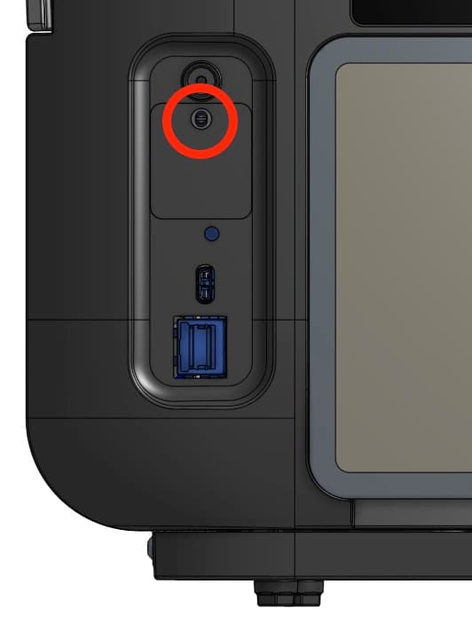
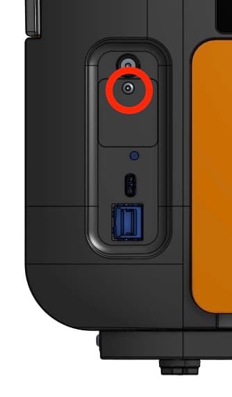
How the motherboard is secured to a Form 4 generation printer depends on when the printer was manufactured. Printers manufactured on or after November 15, 2024 have four screws, accessible by removing the right panel from the printer. Printers manufactured before November 15, 2024 have six screws, two of which require removing additional panels from the printer.
To determine which you have, peel back the serial name sticker on the back-left of the printer. If you see a hex screw, you have an older unit. Continue following the instructions in this guide. If you see a slotted stud, you have a newer unit. Follow the instructions in the guide Replacing the Form 4 motherboard (post 2024-11-15).
Removing the exterior panels
Overview: Remove the exterior panels and the rear mesh filter to access the motherboard.
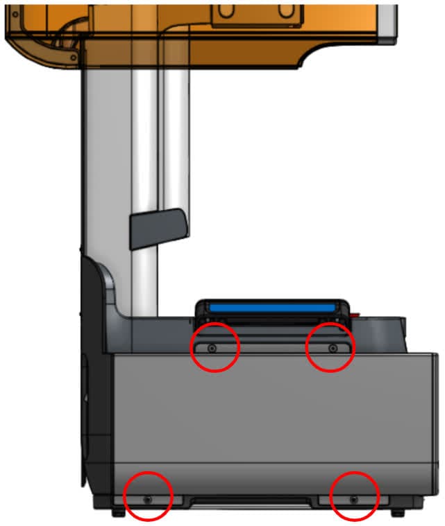
Step 1: Remove the left panel screws
Open the printer cover. Using a 2.5mm hex driver, remove the four screws securing the left exterior panel to the printer. Set the left exterior panel and the screws aside.
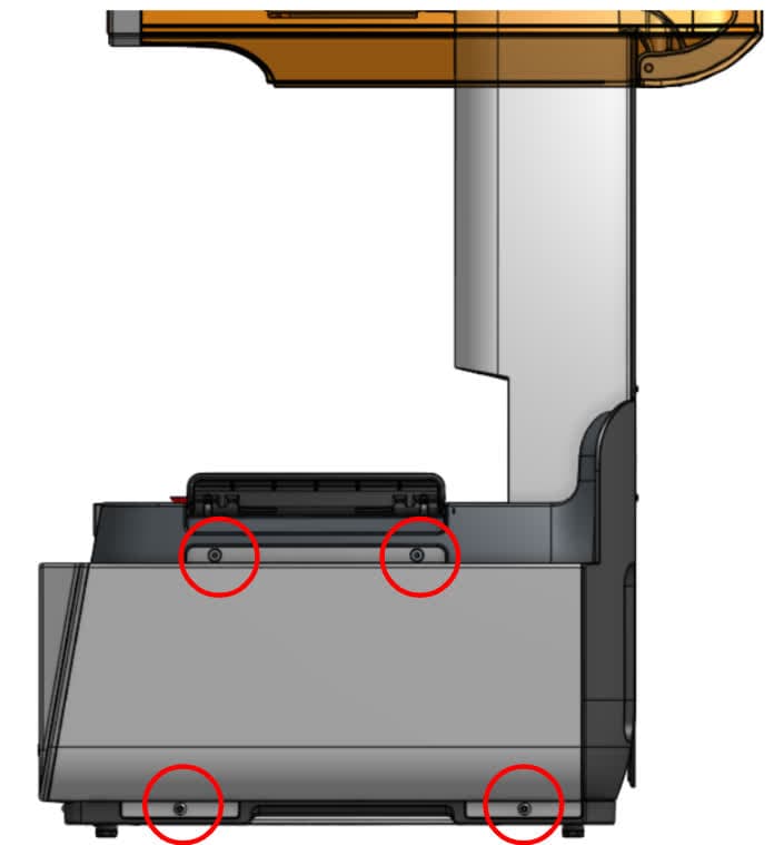
Step 2: Remove the right panel screws
Using a 2.5 mm hex driver, remove the 4 screws securing the right exterior panel to the printer. Set the right exterior panel and the screws aside.
Step 3: Remove the upper back panel
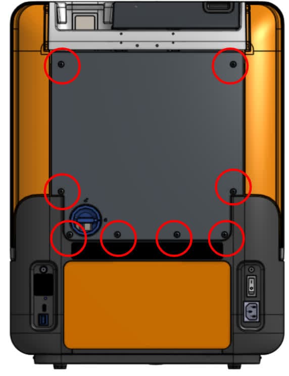
Using a 2.5 mm hex driver, remove the eight screws securing the back panel to the printer. Remove the back panel by sliding it down and away from the back of the printer. Set the back panel and the screws aside.
Step 4: Remove the rear mesh filter
Remove the magnetic rear mesh filter and set it aside.
Removing the LPU
Overview: Loosen the housing screws and remove the LPU.
Notice:
This step involves removing the LPU, which exposes the Form 4 optical system. While the LPU is removed from the printer, ensure that no dust or debris falls into the optical cavity.
Step 1: Loosen the LPU housing screws
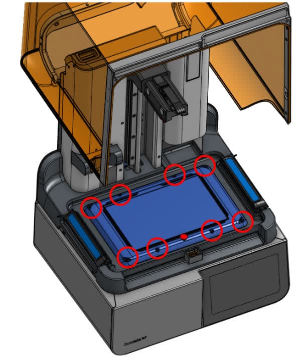
Open the printer cover. Use a 2.5 mm hex driver to loosen the eight captive hex screws in the LPU housing.
Step 2: Unplug the HDMI cable
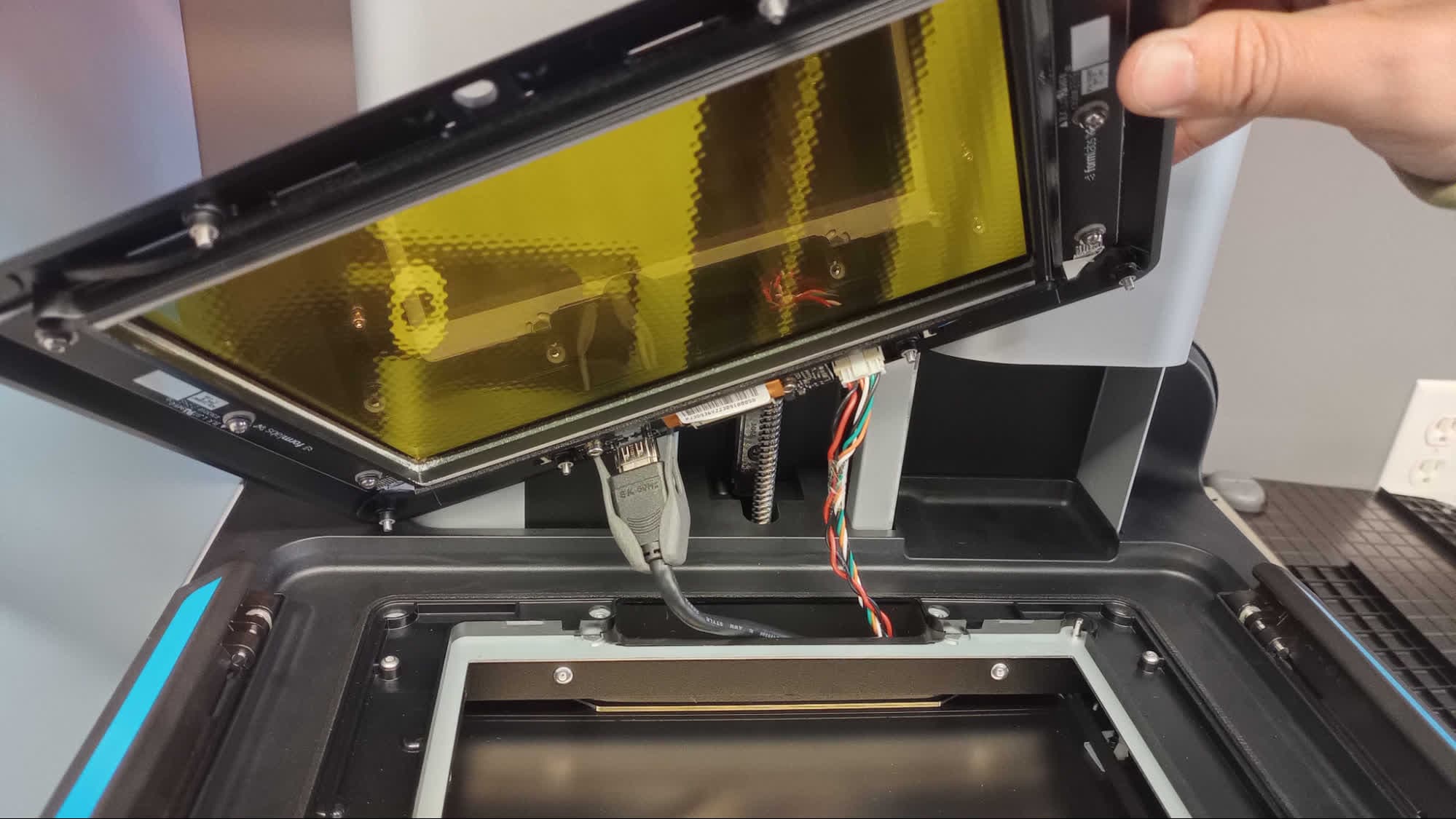
Carefully lift the LPU and tilt it so that the bottom faces you. Locate the LPU’s HDMI cable. Squeeze the plastic retaining clip and unplug the HDMI cable from the LPU.
Step 3: Disconnect the tank heater cable
Release the tank heater cable by squeezing the tab on the connector and pulling directly away from the LPU. Do not pull on the cable itself.
Step 4: Remove the LPU
Remove the LPU from the printer and set it aside.
Removing the resin tank latches
Overview: Locate the retaining tab, remove the pin and spring, and remove the resin tank latches.
Step 1: Locate the retaining tab
The resin tank latch attaches to the printer with two metal pins held in place by a retaining tab. Lift the resin tank latch and locate the black retaining tab behind each pin.
Step 2: Remove the pin and spring
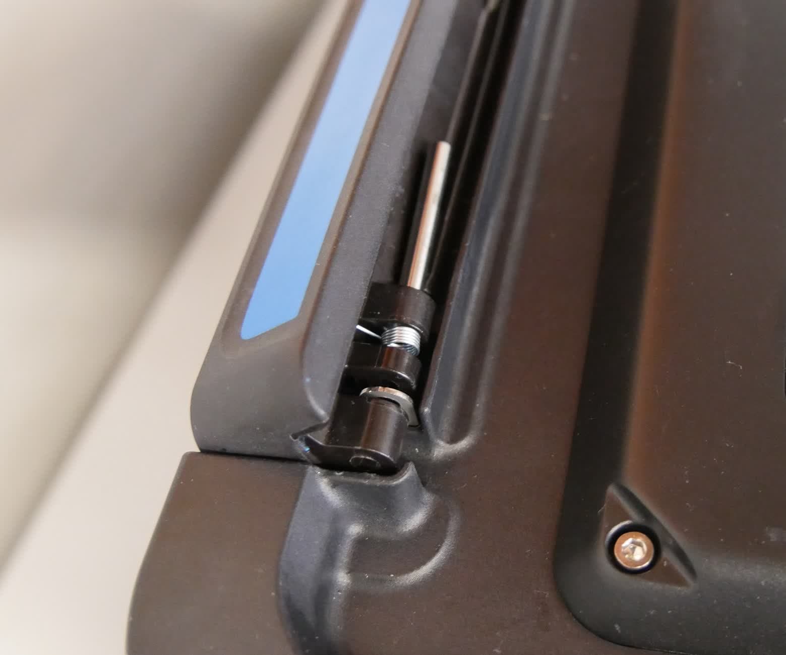
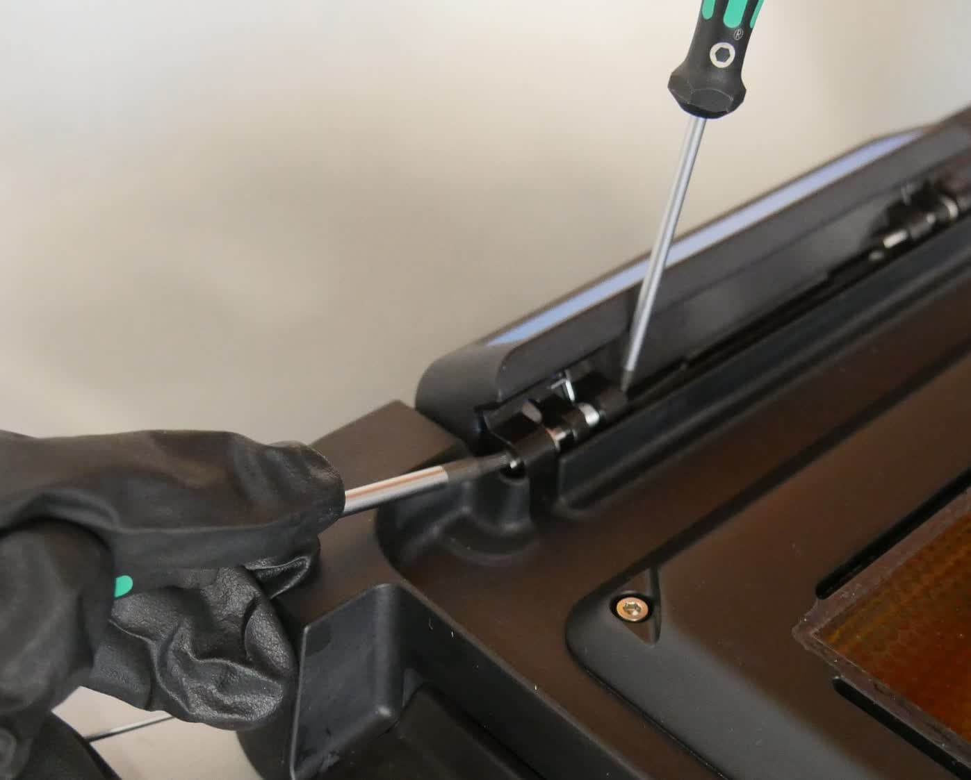
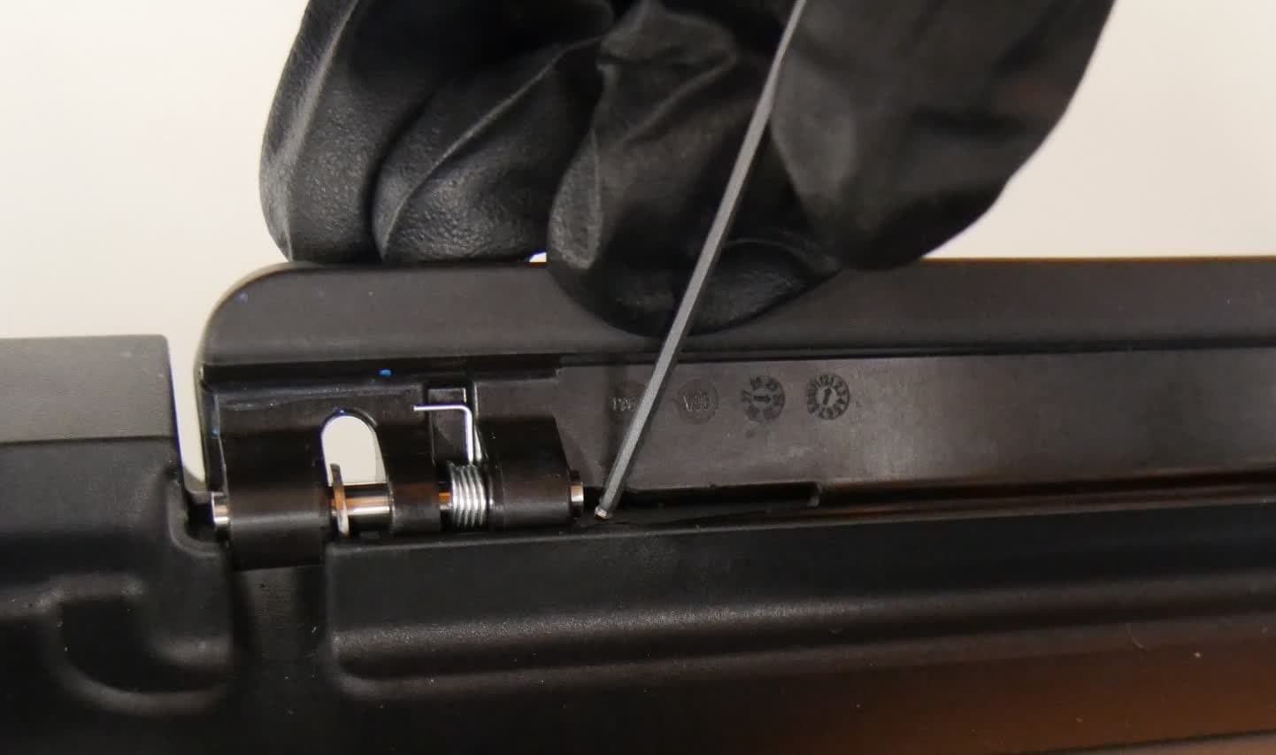
While pressing down on the retaining tab with the 2.5 mm hex driver, use the 2 mm ball-end hex driver to push the pin through the bracket. You may need to use a moderate amount of force to fully push the pin out of its bracket. Once the pin is removed, the spring separates from the bracket. Set the spring and pin aside.
Step 3: Remove the second pin
Repeat steps 1–2 to remove the second pin from the resin tank latch. Note that there is only one spring per latch. The pin with the spring is located closer to the front of the printer.
Step 4: Remove the second resin tank latch
Repeat steps 1–3 to remove the second resin tank latch. Set the resin tank latches aside.
Removing the touchscreen assembly
Overview: Remove the touchscreen assembly from the printer.
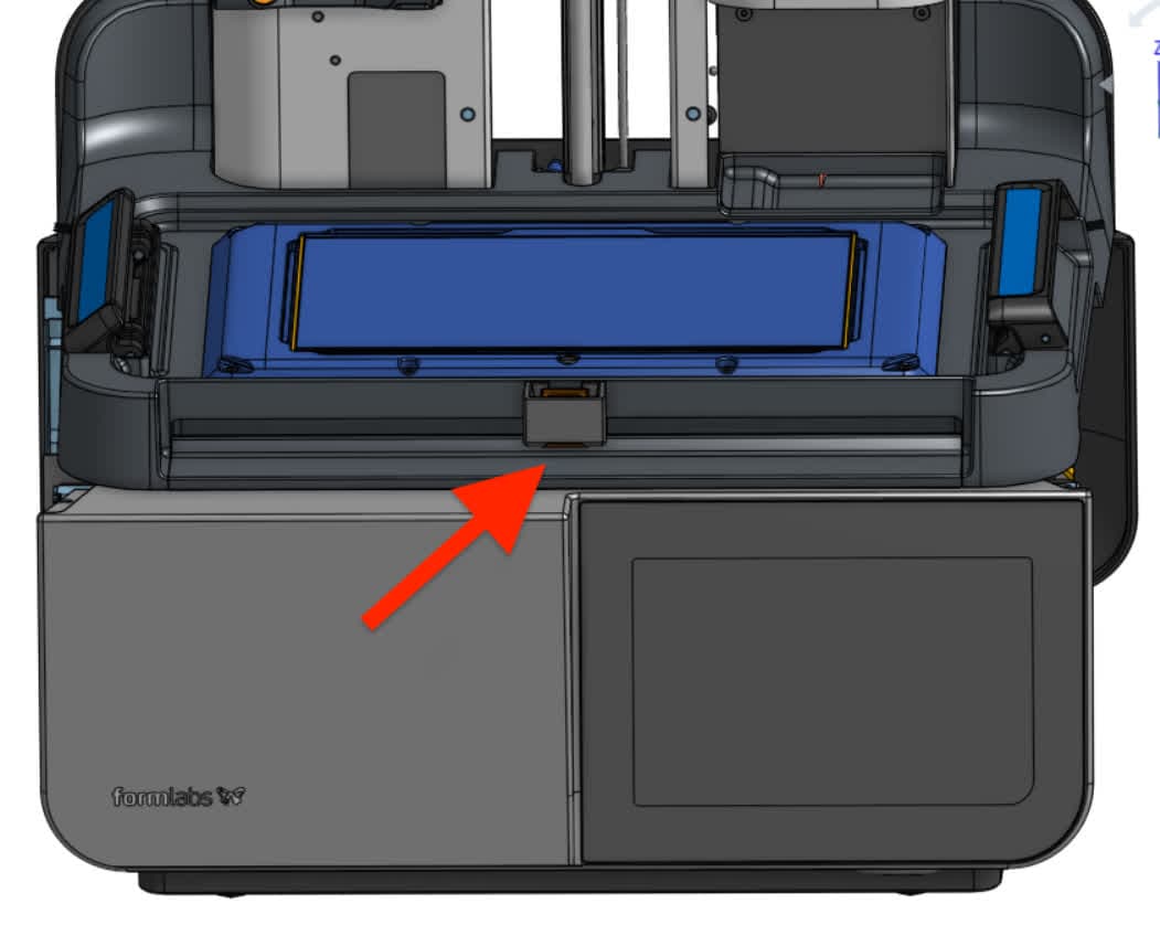
Step 1: Center the mixer base
Open the printer cover and slide the mixer base to the center of the LPU.
Step 2: Remove the left touchscreen assembly retention screws
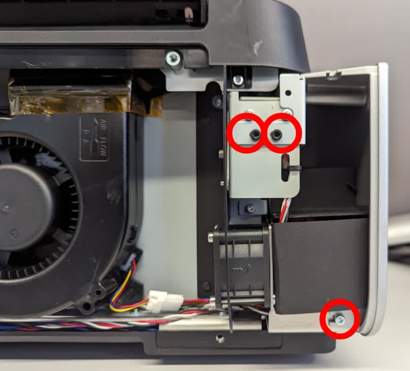
Use a 2.5 mm hex driver to remove the three screws securing the left side of the touchscreen assembly to the printer. Set the screws aside.
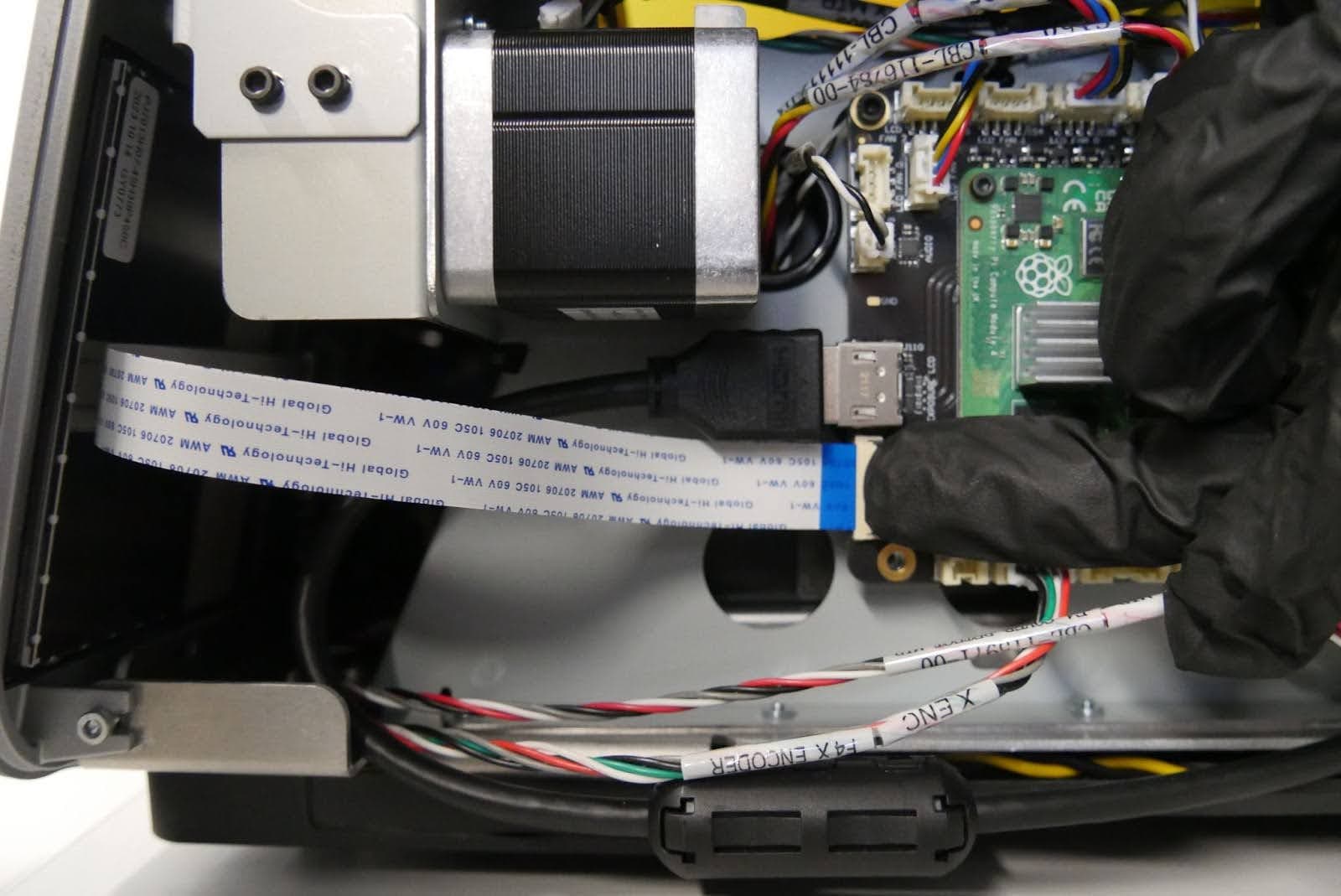
Step 3: Disconnect the touchscreen ribbon cable
The touchscreen ribbon cable is retained with a latch. Rotate the black plastic tab on the connector away from the printer to unlatch the touchscreen ribbon cable from the motherboard. Do not pull on the touchscreen ribbon cable. Once the black tab is properly released, the cable slides out of the connector with minimal force.
Step 4: Remove the right touchscreen assembly retention screws
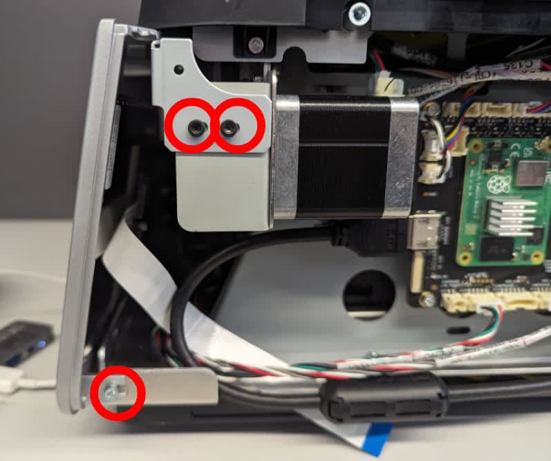
Use a 2.5 mm hex driver to remove the three screws securing the right side of the touchscreen assembly to the printer. Set the screws aside.
Step 5: Rotate the printer
Close the printer cover and carefully lay the printer on its back with the cover facing upwards.
Step 6: Loosen the bottom panel screws
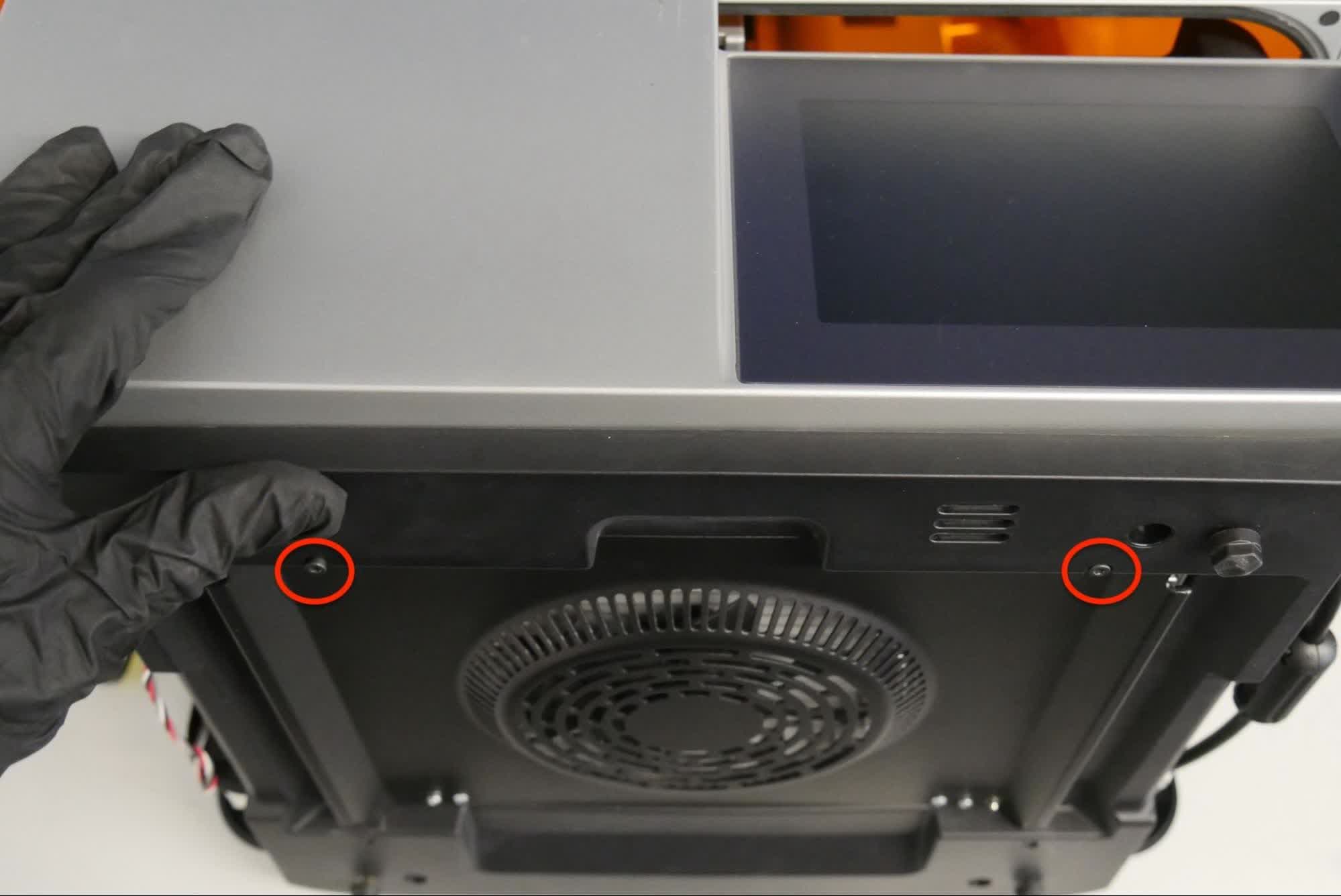
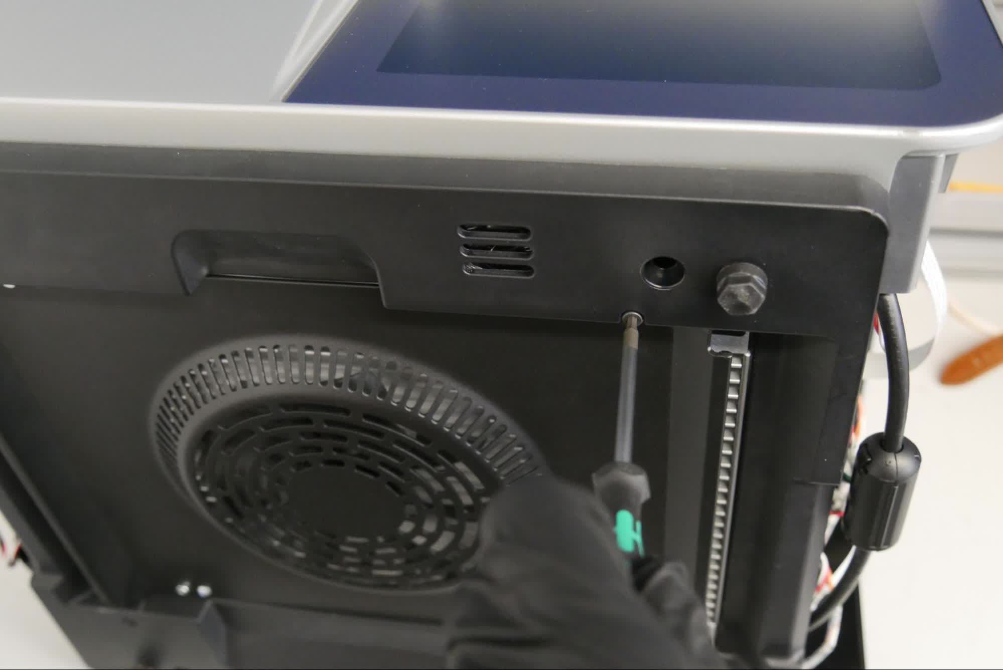
Use a 2.5 mm hex driver to loosen the two screws securing the bottom panel. Do not fully remove the screws.
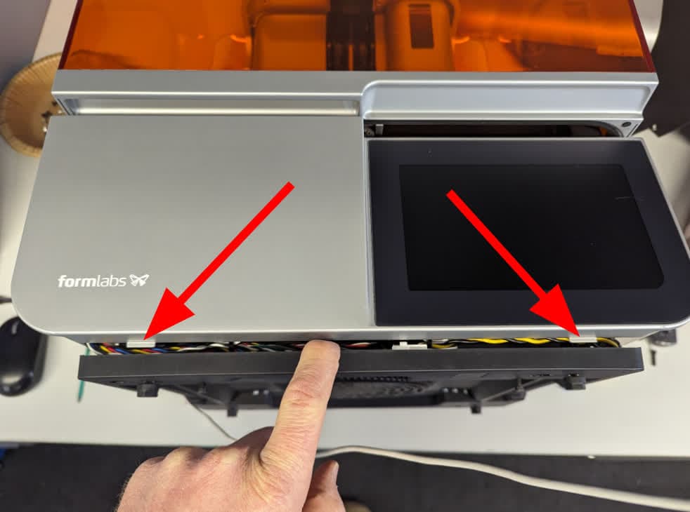
Step 7: Locate the bottom tabs
Gently pull the bottom panel away from the printer to expose the two bottom tabs of the touchscreen assembly. If the tabs are not visible, loosen the two bottom panel screws further.
Step 8: Remove the touchscreen assembly
Grip the touchscreen assembly by its bottom corners. Carefully pull the touchscreen assembly towards you. The bottom of the touchscreen assembly fits snugly to the printer and may require extra force to remove. Rotate the touchscreen assembly until its back surface is visible. Do not pull away from the printer until the touchscreen ribbon cable is disconnected.
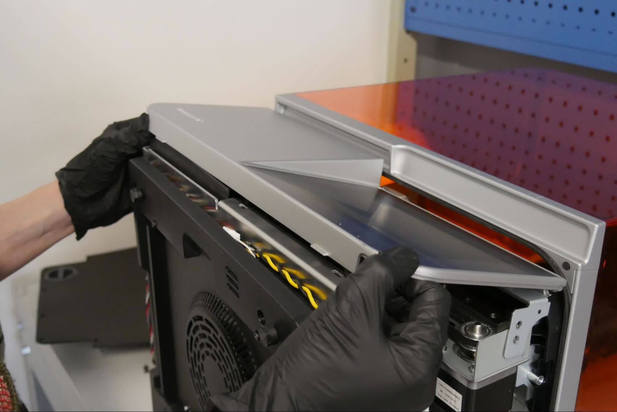
Step 9: Disconnect the touchscreen ribbon cable
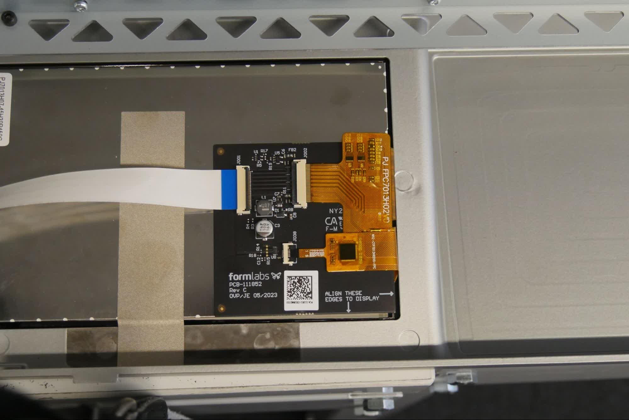
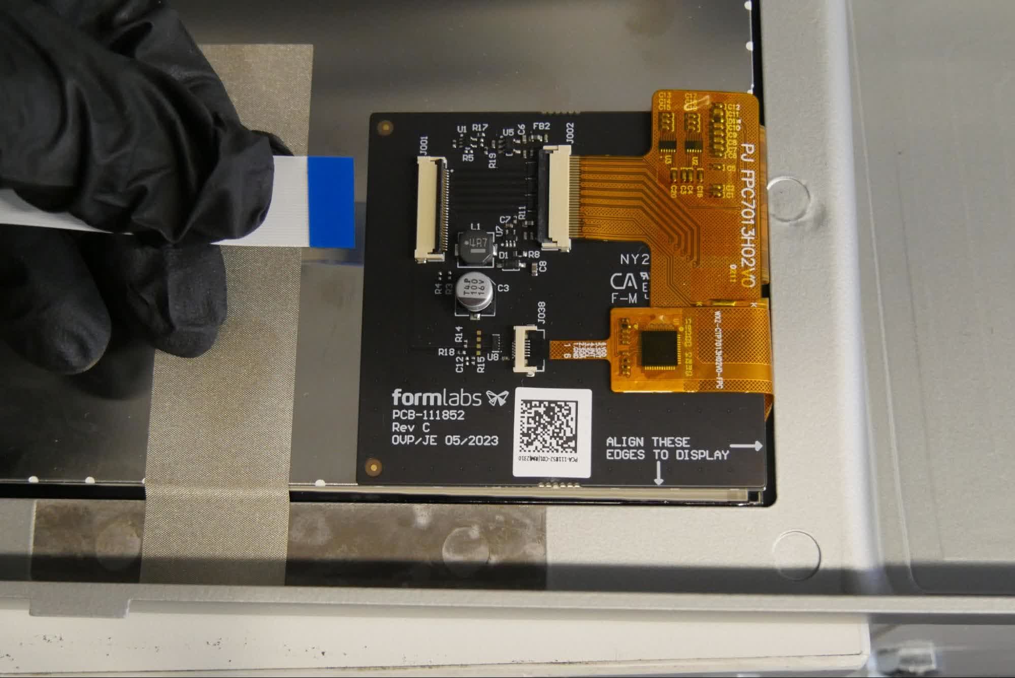
Rotate the black plastic tab on the connector away from the touchscreen assembly to unlatch the touchscreen ribbon cable. Do not pull on the cable. Once the black tab is properly released, the cable slides out of the connector with minimal force. Set the display assembly aside.
Removing the nest
Overview: After removing the LPU, remove the nest.
Step 1: Remove the side screws
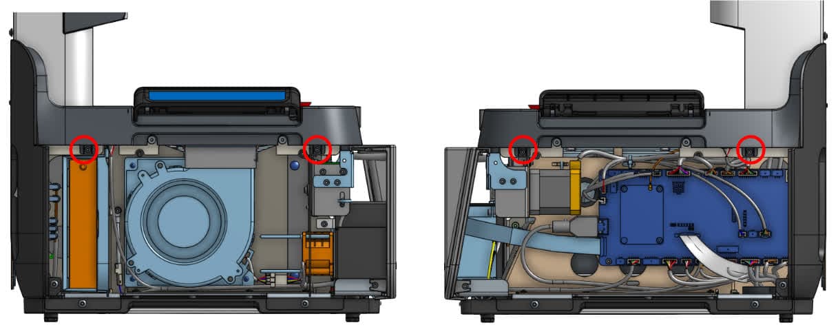
There are two side screws each on the left and right sides of the printer that secure the nest to the printer. Using a 2.5 mm hex driver, remove the side screws. Set the screws aside.
Step 2: Remove the top screws
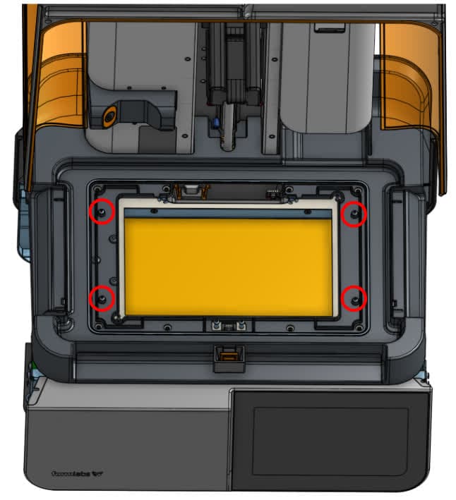
Use a 2 mm hex driver to remove the four screws on the top of the nest. Set the screws aside.
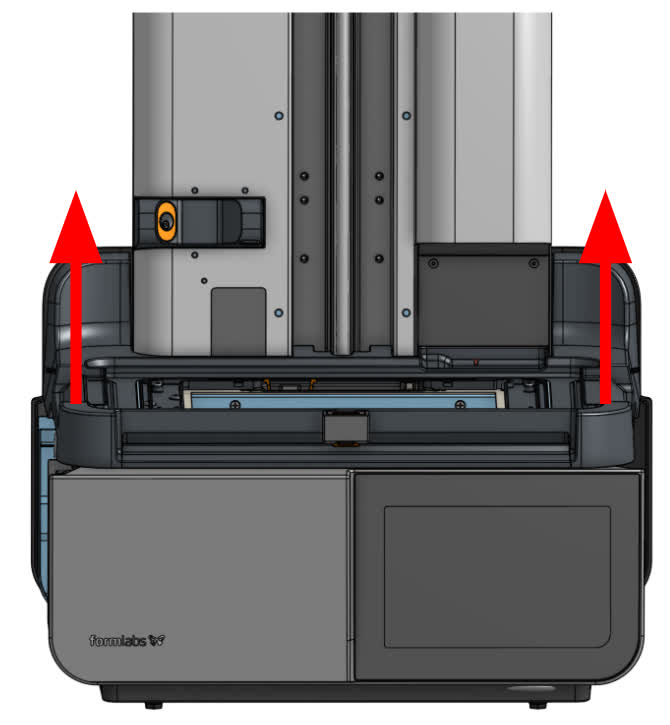
Notice:
Take care when removing the nest and make sure to unhook the cables. Take care when unplugging the cable to avoid damage. Once the plastic tab is pressed, the cable will easily slide from the connector. Do not pull on the wires.
Step 4: Disconnect the interlock cables
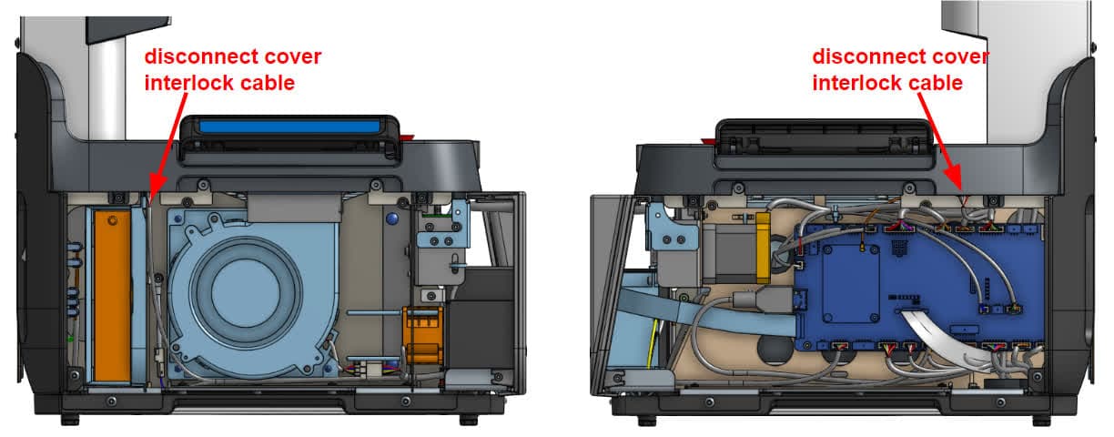
Unplug the cables from the cover interlock boards attached to the nest. Set the nest aside.
Removing the lower back panel
Overview: After removing the nest, remove the lower back panel.
Step 1: Remove the side screws
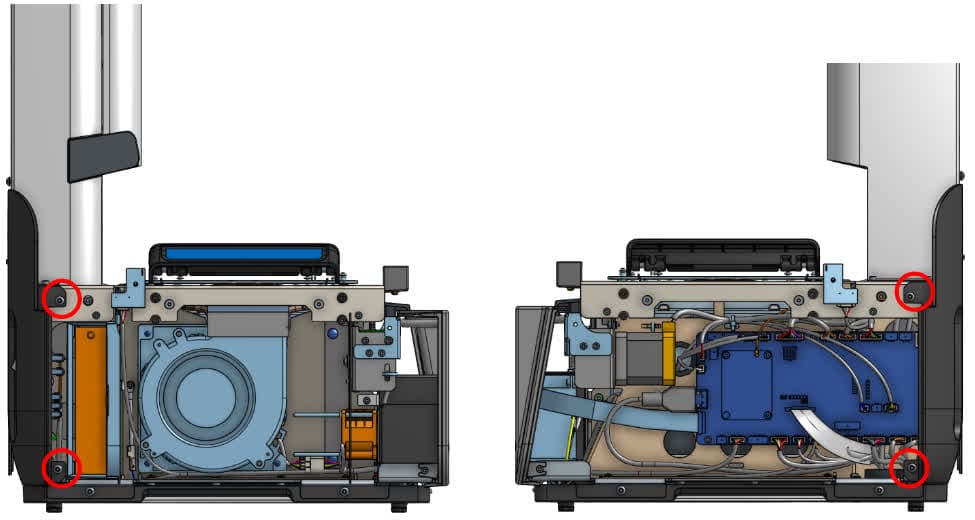
Using a 2.5 mm hex driver, remove the two screws on the left side and the two screws on the right side that secure the lower back panel to the printer. Set the screws aside.
Step 2: Remove the back screws
Using a 2.5 mm hex driver, remove the four screws that secure the lower back panel to the printer. Set the screws aside.
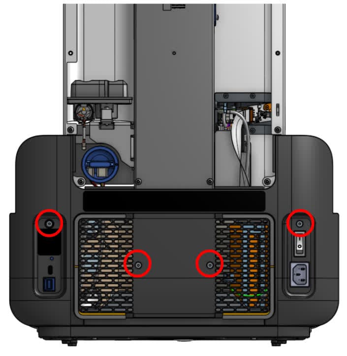
Step 3: Remove the lower back cover
Remove the lower back cover and set aside.
Removing the motherboard
Overview: After removing the exterior panels, remove the motherboard.
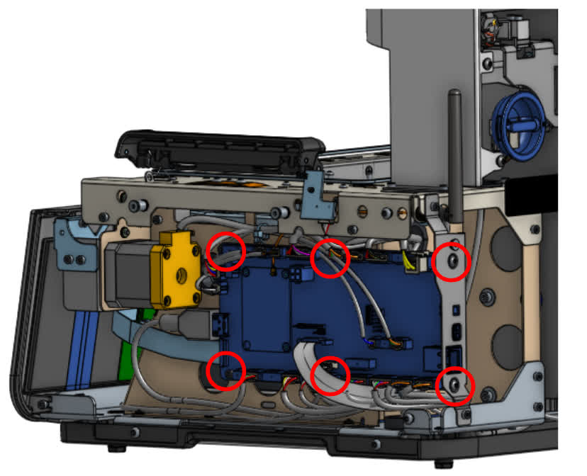
Warning:
Take care when unplugging the cable to avoid damage. Once the plastic tab is pressed, the cable will easily slide from the connector. Do not pull on the wires.
Installing the replacement motherboard
Overview: After removing the old motherboard, connect and install the replacement.
Step 1: Install the motherboard mounting screws
Position the motherboard on the right side of the printer so the screw holes are aligned. Using a 2.5 mm hex driver, install the four hex screws on the left side of the motherboard. Using a 2 mm hex driver, install the two hex screws on the back of the printer. Do not overtighten the screws.
Step 2: Connect the cables to the motherboard
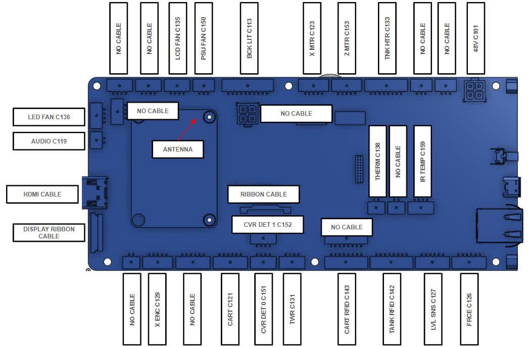
Reconnect all cables to the motherboard. Use the nu mbered labels on the cables and the matching labels printed on the motherboard.
Installing the lower back panel
Overview: After replacing the motherboard, install the lower back panel.
Step 1: Position the panel
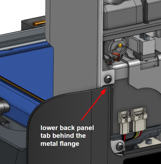
Align the lower back panel. Ensure that the motherboard ports, power switch, and power socket align with the corresponding slots on the lower back panel. Ensure that the two tabs at the top of the lower back panel are positioned behind the metal flanges on the tower panels.
Step 2: Install the back screws
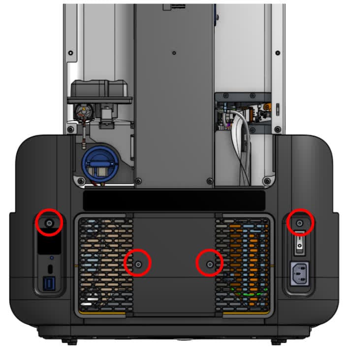
Using a 2.5 mm hex driver, install the four screws that secure the lower back panel to the printer. Tighten the screws until snug.
Step 3: Install the side screws
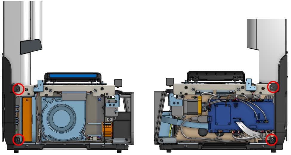
Using a 2.5 mm hex driver, install the two screws on the left side and the two screws on the right side that secure the lower back panel to the printer.
Installing the nest
Overview: After installing the lower back panel, install the nest.
Step 1: Position the nest
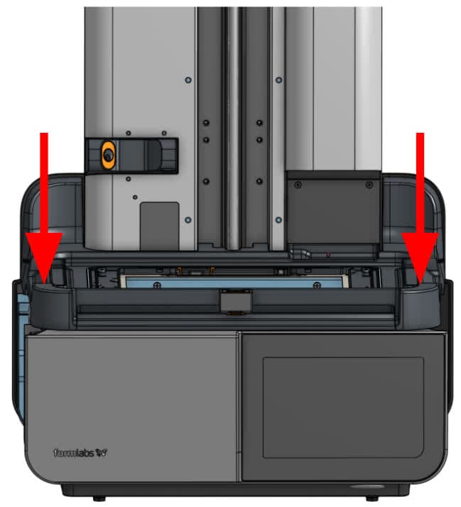
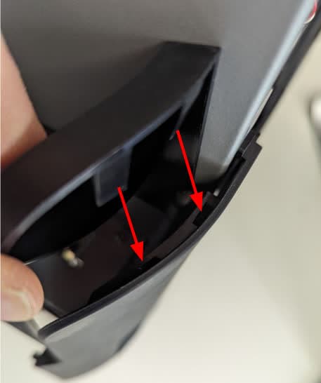
Lower the nest down onto the printer. Note that the front edge has a gasket and will provide some resistance. Ensure that the flanges on the rear of the nest are inserted into the corresponding slots in the lower back panel.
Step 2: Install the top screws
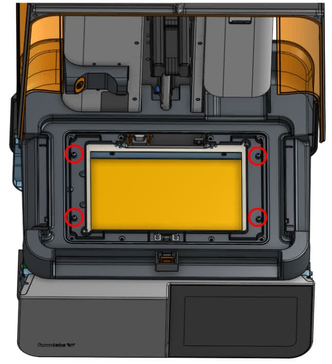
Use a 2 mm hex driver to install the four screws on the top of the nest. Tighten the screws until finger tight.
Step 3: Install the side screws
Use a 2.5 mm hex driver to install the two screws on the left side and the two screws on the right side that secure the nest to the printer.

Step 4: Connect the cover interlock cables
Connect the cover interlock cables on each side of the nest. The plastic tabs should click into place to secure the connection.
Reinstalling the touchscreen assembly
Overview: After installing the nest, reinstall the touchscreen assembly.
Step 1: Connect the touchscreen ribbon cable to the display assembly
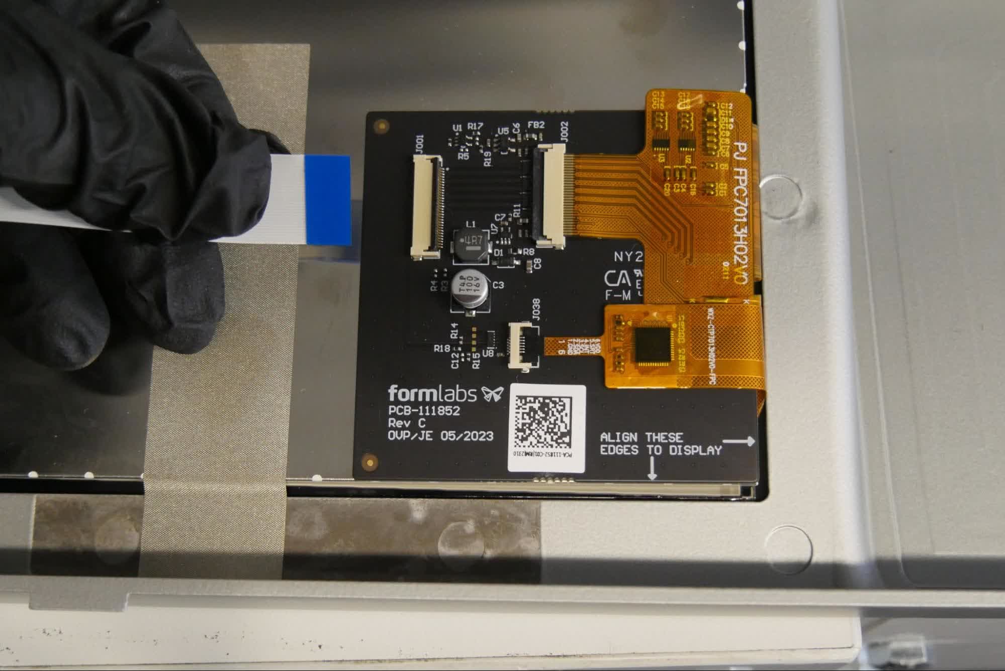
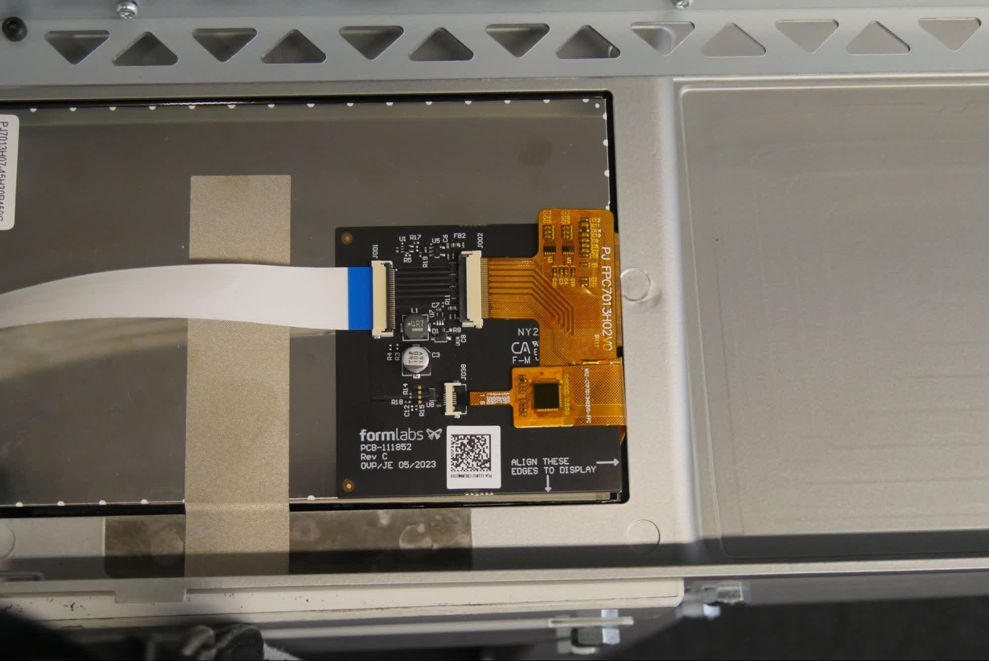
Slide the ribbon cable into the connector on the touchscreen assembly. Make sure the cable is inserted evenly. The blue mark should face upward.
Step 2: Secure the ribbon cable
Flip down the black tab on the connector to secure the cable to the touchscreen assembly. Take care not to pull on the cable during installation.
Step 3: Position the touchscreen assembly for installation

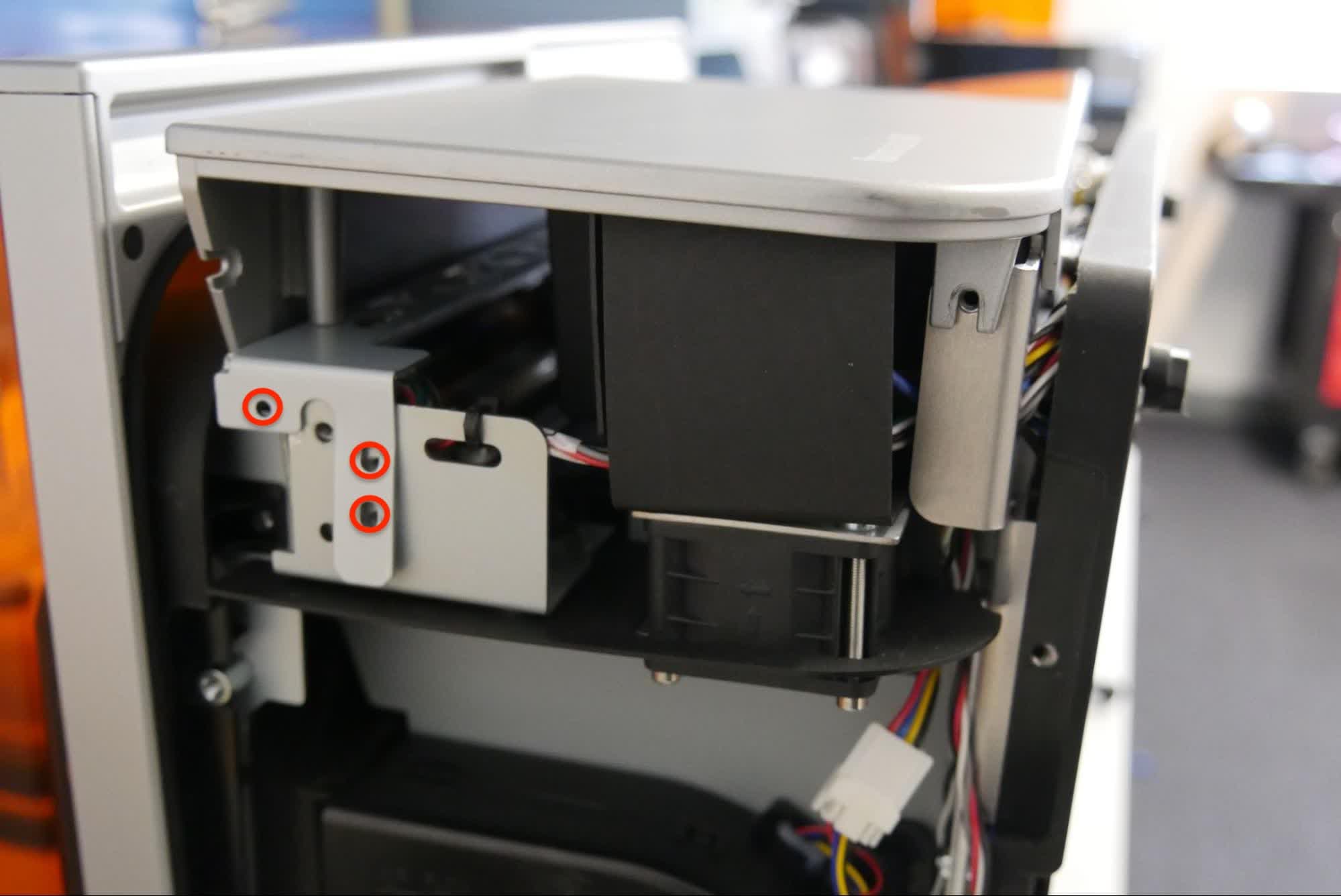
Position the touchscreen assembly on the printer. Make sure that the sheet metal tabs are positioned outside of the printer frame and that they align with the screw holes on the printer. Take care not to crush or fold the touchscreen ribbon cable.
Step 4: Tighten the bottom panel screws
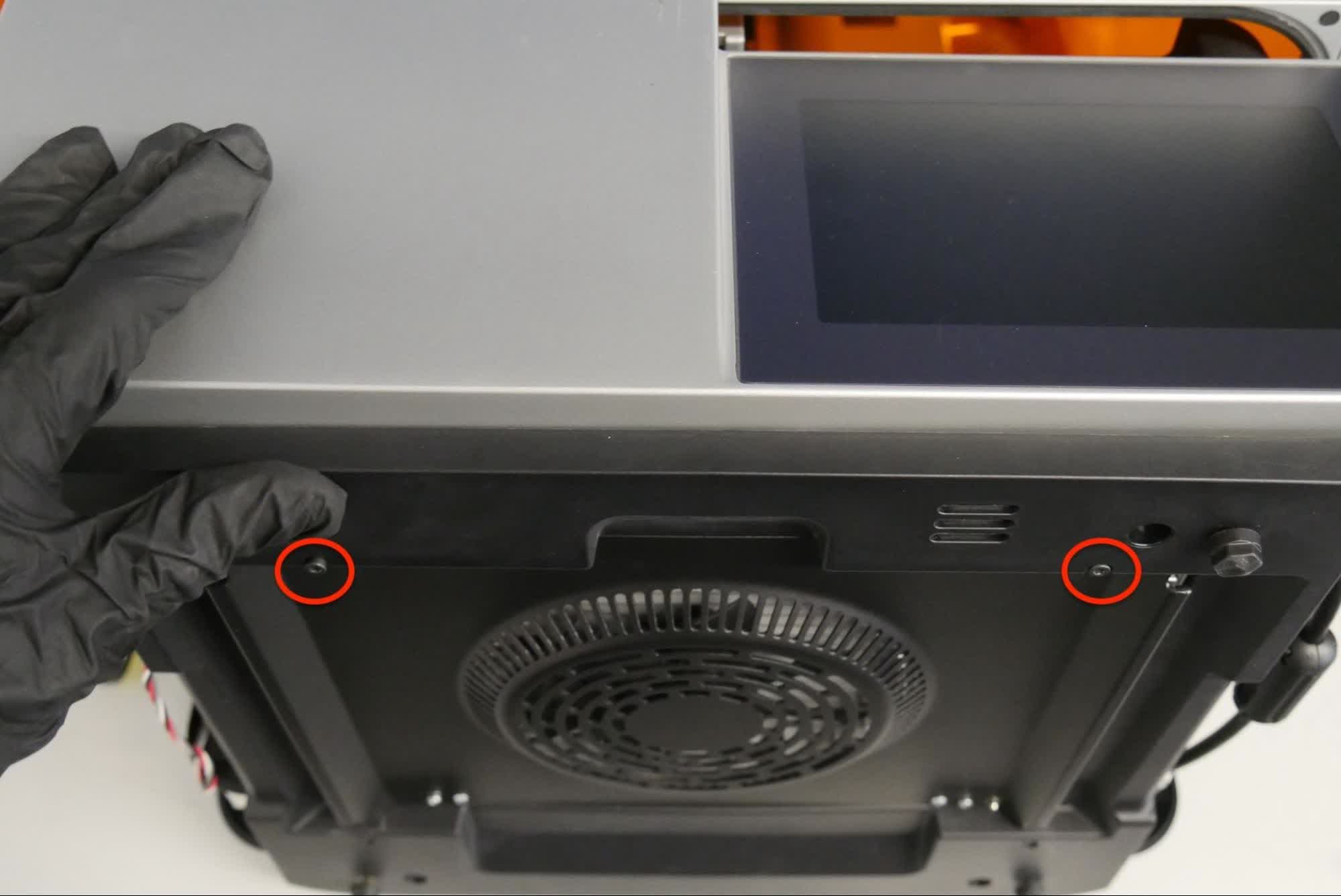
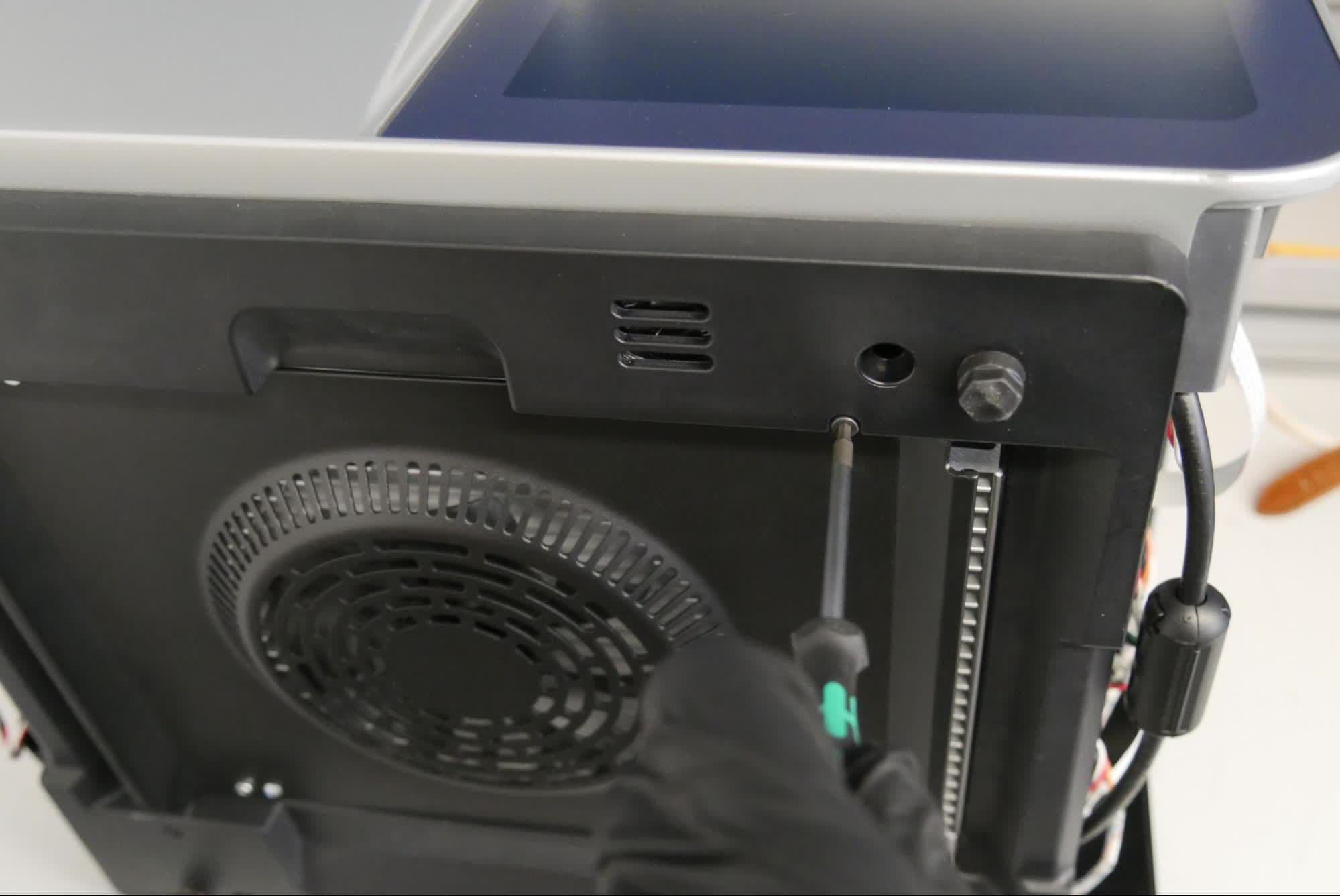
Make sure that the two bottom tabs of the touchscreen assembly can slide into the printer before tightening the screws. Use a 2.5 mm hex driver to tighten the two screws that secure the bottom panel to the printer.
Step 5: Set the printer upright
Rotate the printer to sit upright.
Step 6: Install the right touchscreen assembly screws
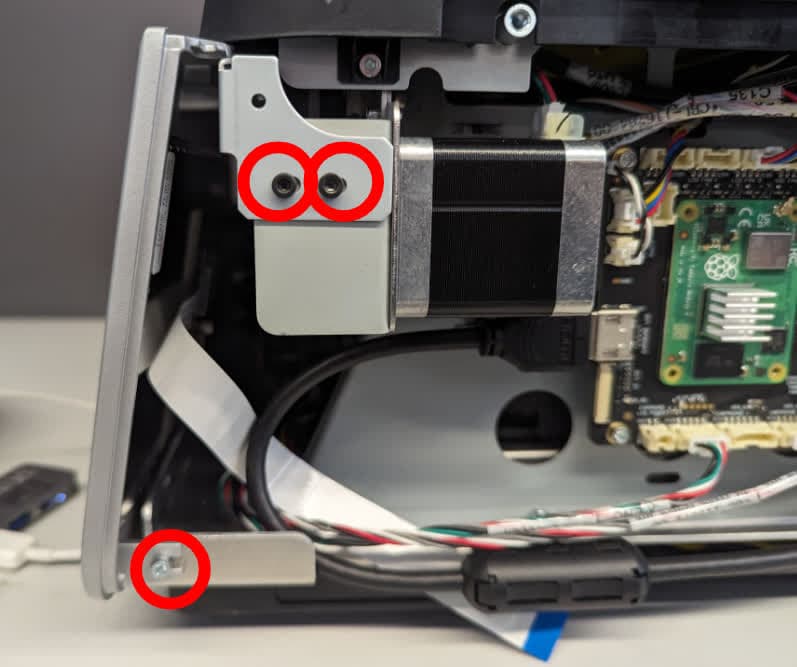
Use a 2.5 mm hex driver to install the three screws securing the right side of the touchscreen assembly to the printer. Tighten the screws until snug.
Step 7: Reconnect the touchscreen ribbon cable
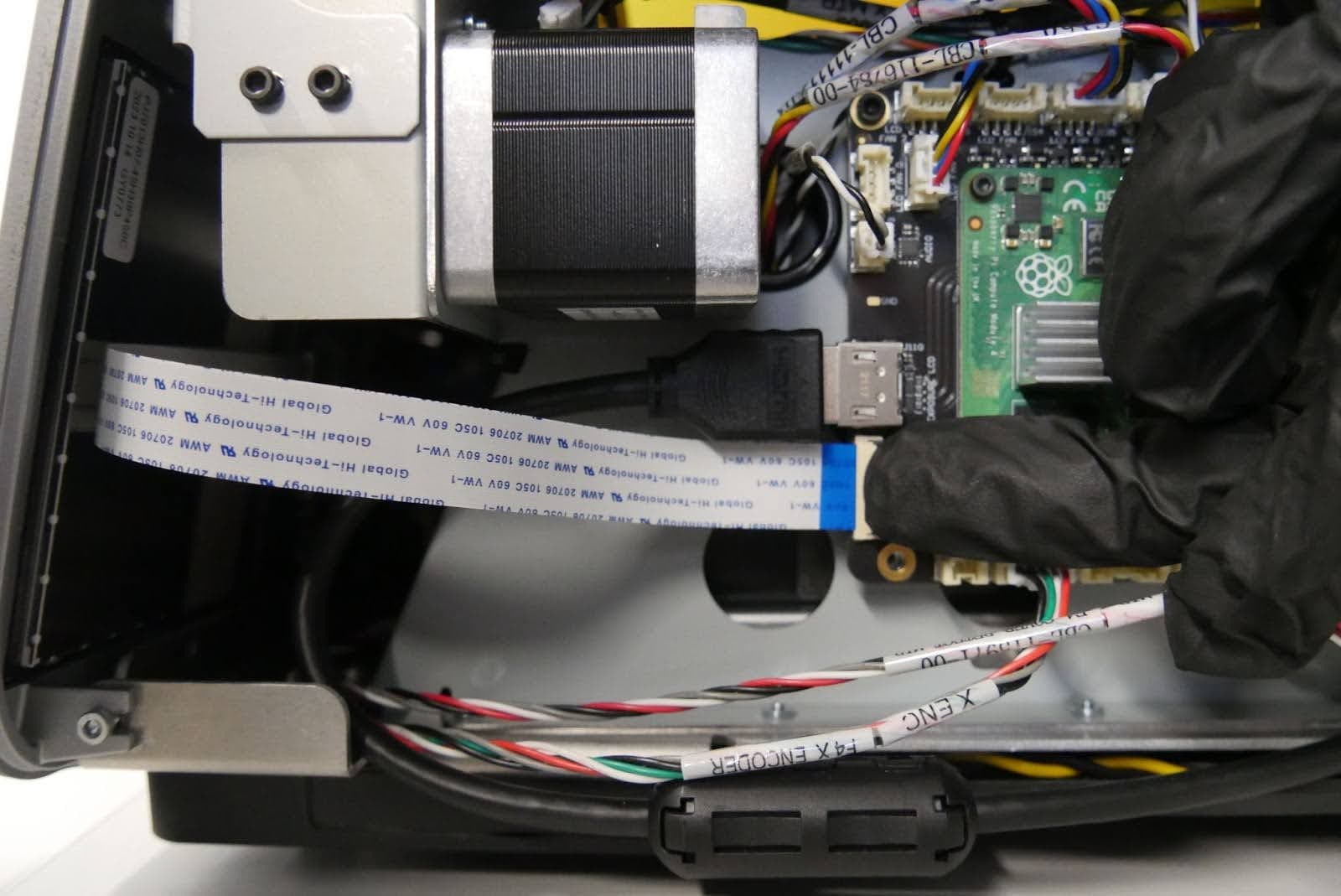
Reconnect to the touchscreen ribbon cable to the motherboard. Make sure it is inserted evenly. The blue mark should face outwards. Flip down the black tab on the connector to secure the cable to its connector. Take care not to pull on the cable during installation.
Step 8: Install the left touchscreen assembly screws
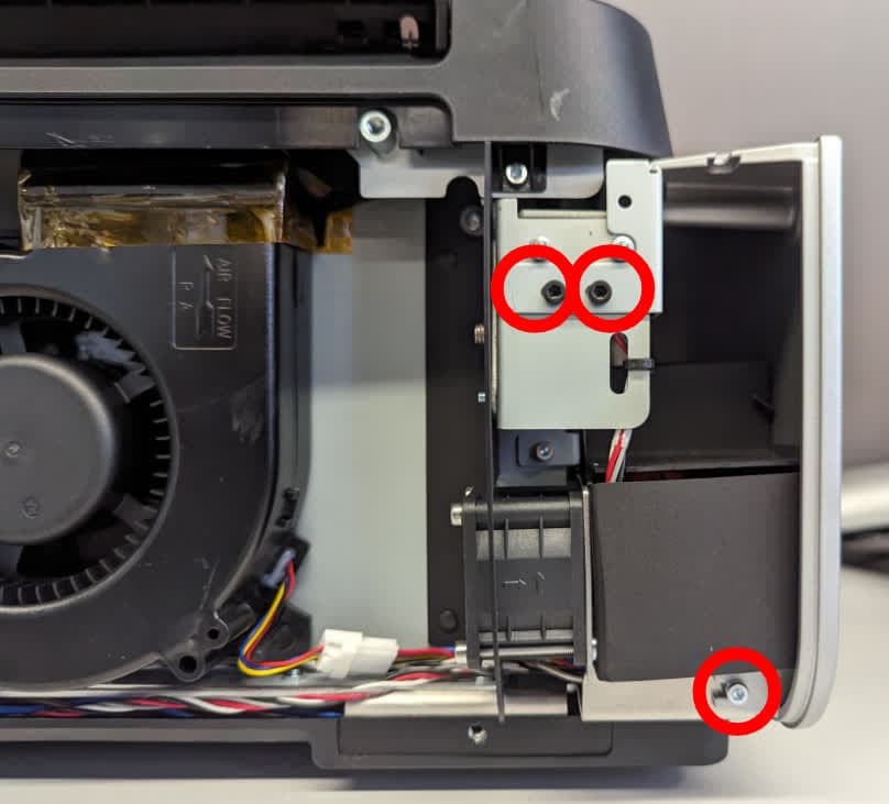
Use a 2.5 mm hex driver to install the three screws that secure the left side of the touchscreen assembly to the printer. Tighten the screws until snug.
Reinstalling the resin tank latches
Overview: After reinstalling the touchscreen assembly, reinstall the resin tank latches.
Step 1: Pre-assemble the resin tank latch
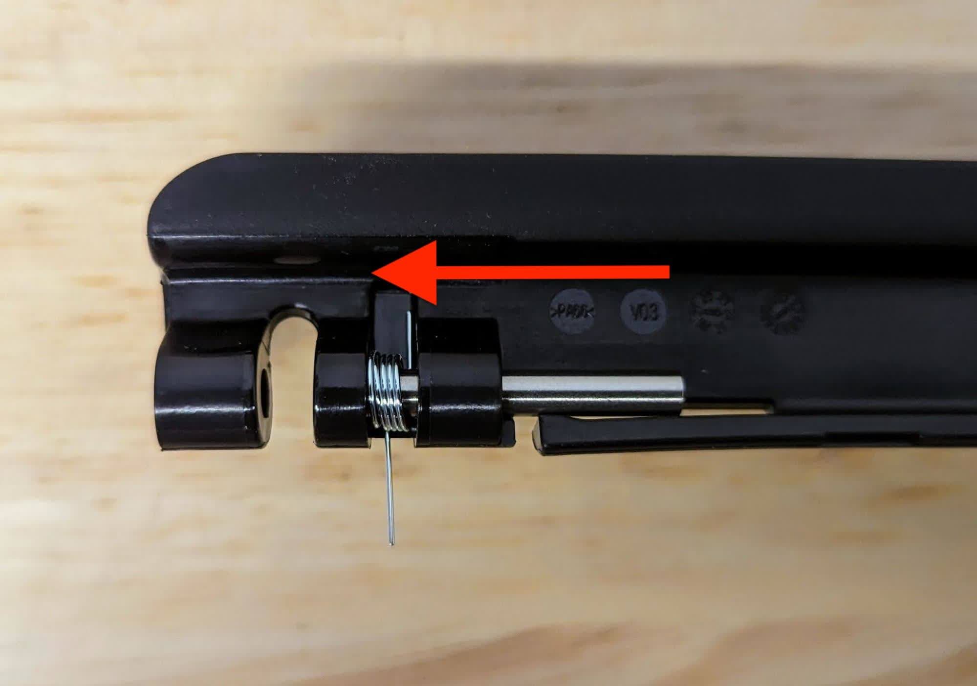
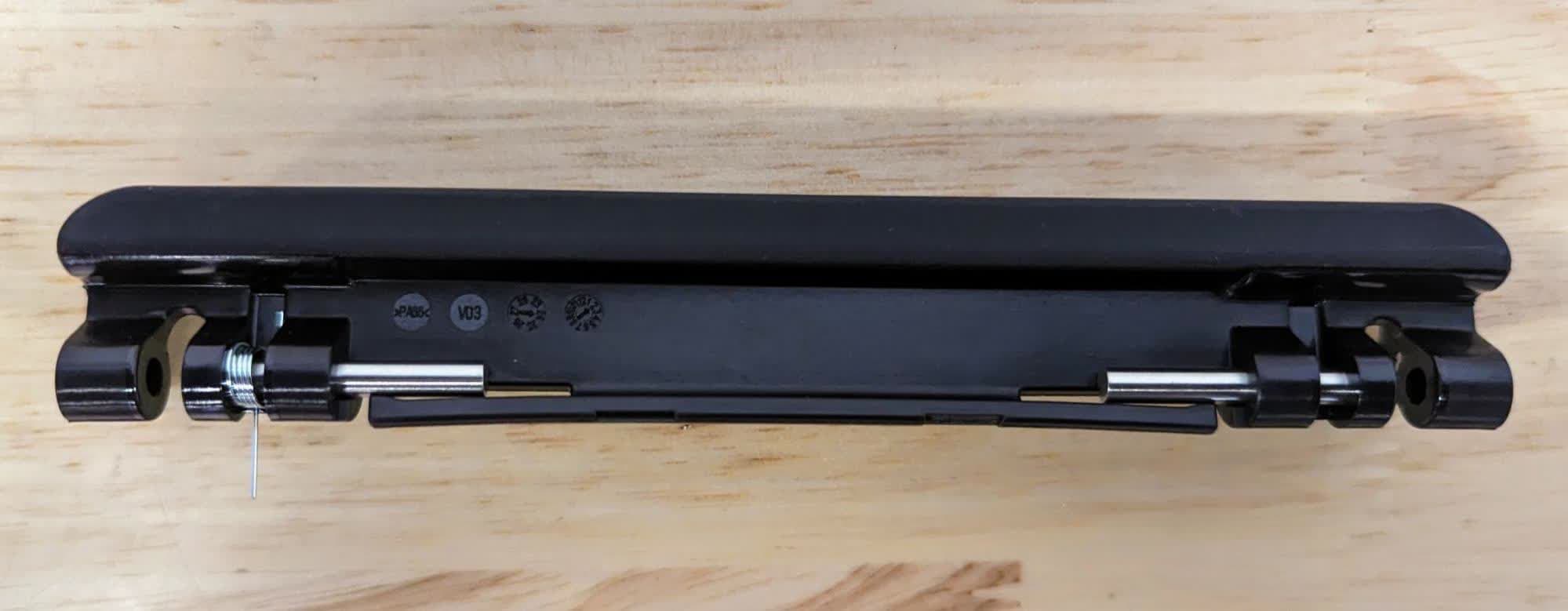
The resin tank latch needs to be partially assembled before installing it onto the printer. Slide the metal pins into the bracket from the inside of the latch. Insert the spring as shown with the shorter leg pressed against the latch. The pin threads through the spring. Leave space in the bracket for installation.
Repeat the previous step to thread the pin through the second bracket. Note that there is only one spring per latch, and the spring should be positioned such that it will be towards the front of the printer once the latch is installed.
Step 2: Align the resin tank latch with the printer
Align the resin tank latch with the pins and spring facing towards the LPU.
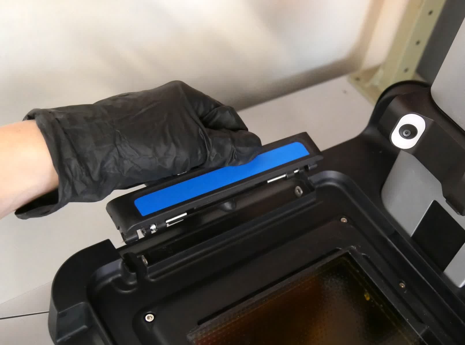
Step 3: Mount the resin tank latch
Lower the latch into place, ensuring that the longer spring leg sits in the small hole towards the front of the printer. The handle should fit easily with little force.
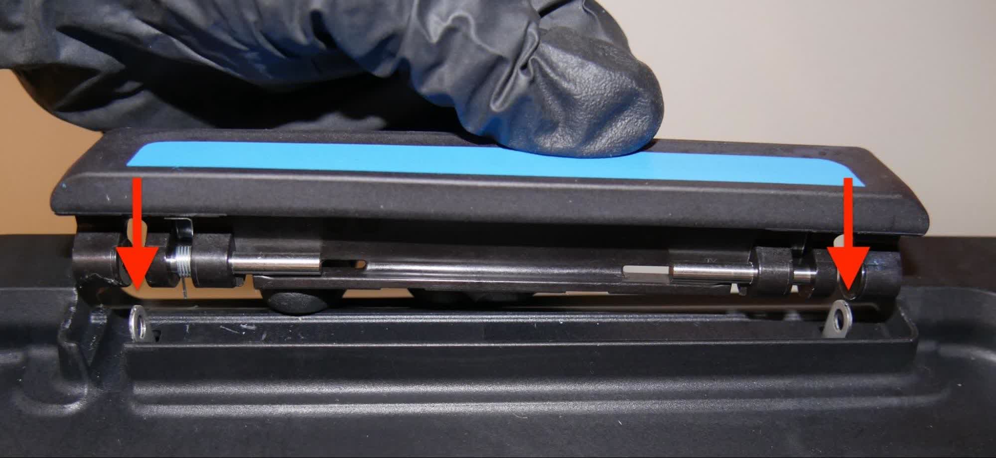
Step 4: Install the pin
Adjust the latch as needed so that the pins align with the metal tabs. Press down on the retaining tab with the 2.5 mm hex driver. Use the 2 mm ball-end hex driver to push the pin through the bracket. You may need to use moderate force to seat the pin. The pin is fully seated when the retaining tab clicks into place behind the pin.
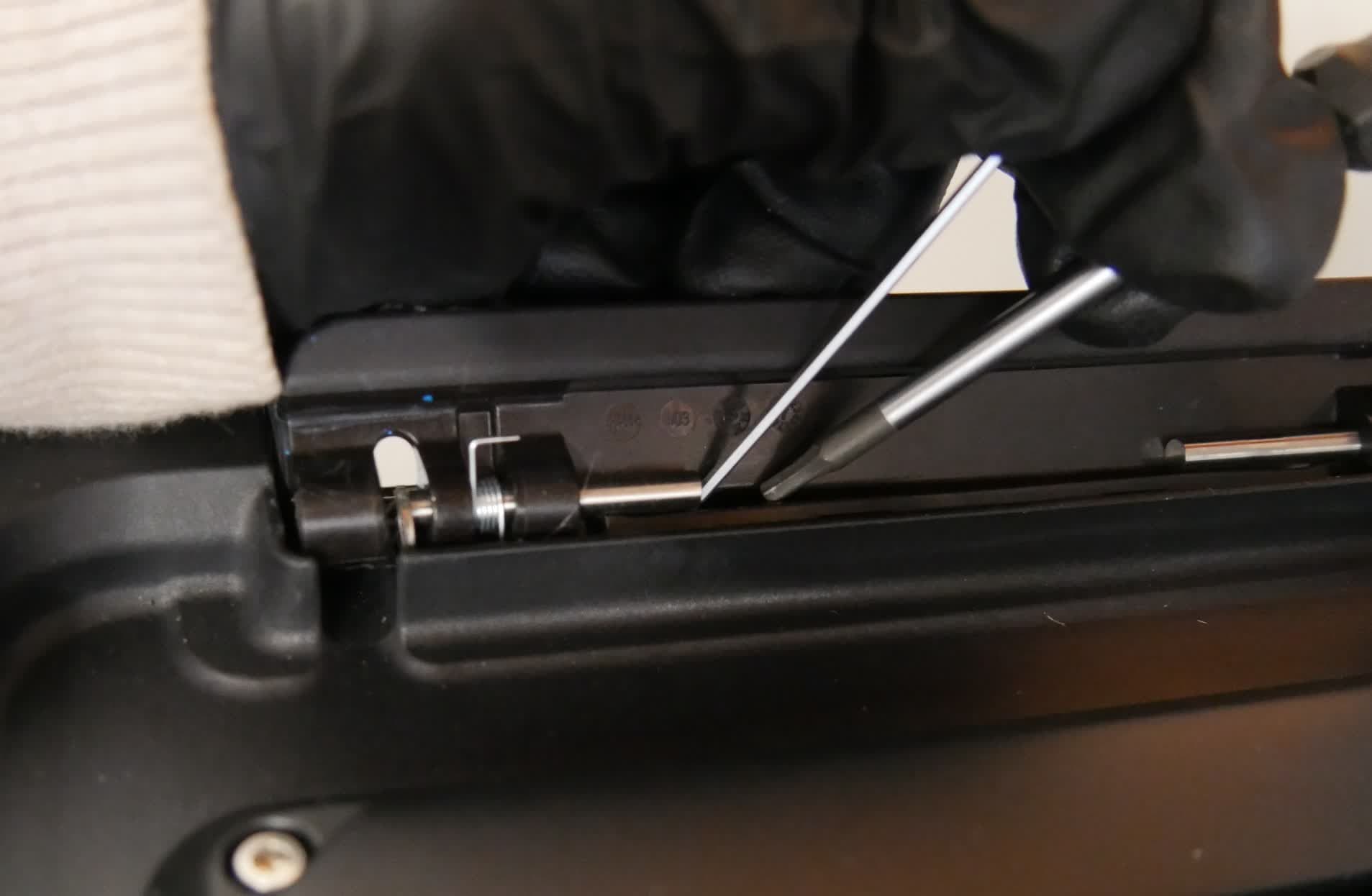
Step 5: Install the second pin
Repeat the previous step to install the second pin in the resin tank latch. Note that there is only one spring per latch, located towards the front of the printer.
Step 6: Repeat
Repeat steps 2-4 on the second resin tank latch.
Reinstalling the LPU
Overview: After replacing the motherboard, connect and reinstall the LPU.
Step 1: Connect the tank heater cable
Position the LPU so the connector ports are oriented towards the back of the printer. Plug the tank heater cable into the connector on the LPU. The plastic tab should click into place to secure the cable.
Step 2: Connect the HDMI cable
Plug the HDMI cable into the port on the LPU. Ensure that the two prongs on the plastic retaining clip snap into place.
Step 3: Mount the LPU
Ensure that the optical cavity and LPU are free from dust and debris. Place the LPU onto the optical cavity and align the screw holes.
Step 4: Thread the housing screws
Use a 2.5 mm hex driver to loosely thread the eight captive hex screws in the LPU housing.
Step 5: Secure the LPU
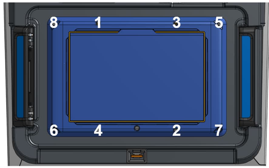
Once all screws are loosely threaded, tighten the screws in a diagonal pattern as shown above. The screws should be secure but not overtightened. To avoid overtightening, grip the short end of the hex driver.
Reinstalling the exterior panels
Overview: Install the left, right, and upper back exterior panels. Also install the rear mesh filter.
Step 1: Reinstall the rear mesh filter
Reattach the mesh filter to the printer, ensuring that it is aligned with the air intake vents.
Step 2: Install the upper back panel
Slide the back cover into place on the back of the printer. Using a 2.5 mm hex driver, install the eight screws that secure the back panel to the printer. Tighten the screws until snug.
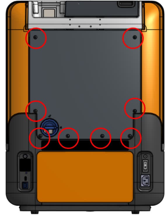
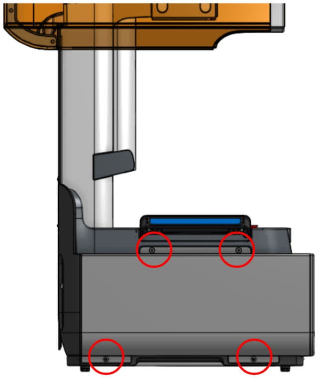
Step 3: Install the left panel screws
Using a 2.5 mm hex driver, install the four screws that secure the left exterior panel to the printer. Tighten the screws until snug.
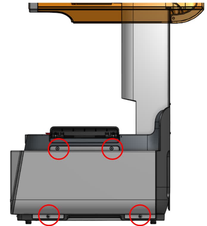
Step 4: Install the right panel screws
Using a 2.5 mm hex driver, install the four screws that secure the right exterior panel to the printer. Tighten the screws until snug.
Finalizing the repair
Overview: After installing the new motherboard, power on the printer and perform final checks.
Step 1: Power on the printer
Close the printer cover and connect the power cable to the printer and the power supply. Turn on the switch at the back of the printer. The printer turns on and initializes.
Step 2: Run the Align build platform calibration
From the printer touchscreen, select Settings > Tools > Align build platform and follow the on-screen instructions.
Step 3: Re-activate biocompatible license (Form 4B customers only)
After the motherboard replacement, the biocompatible license will be temporarily disabled. Connect the printer to the internet to automatically refresh the license.
Step 4: Run a test print
Insert any missing consumables and upload and start a print. Check that the print starts normally and the parts print successfully. Contact Formlabs Support or your authorized reseller to share the results of the procedure.