
Required Supplies:
Formlabs:
- Replacement high voltage control board
- 2.5 mm hex driver (included in the Form 4 or Form 4L tool caddy)
Third-party:
- Nitrile gloves
- Anti-static grounding strap

The Form Cure L V2 high voltage control board controls high voltage power to heaters and other components. It is located behind the rear shell of the machine. A malfunctioning high voltage control board may prevent the machine from functioning properly.
Use this guide to replace the high voltage control board on a Form Cure L V2.
Required Supplies:
Formlabs:
Third-party:
Estimated time:
15–20
minutes
Danger:
Read and follow all safety instructions and warnings in the operator manual. Replacement with incorrect parts can lead to burns, shock, fire, or explosion. Dispose of all parts in accordance with local regulations.
Preparing the workspace
Overview: Prepare the Form Cure L V2 and workspace for replacing the high voltage control board.
Step 1: Prepare the workspace
Clear a workspace around your machine. Ensure that the workspace is well-ventilated and free of dust.
Step 2: Unplug the machine
Turn off the machine using the power switch on the back of the unit. Disconnect the power cable before continuing with maintenance. Do not perform maintenance on the machine while it is connected to power. Wait five minutes after disconnecting the machine from power before proceeding. If the machine was recently in use, the post-cure chamber will be warm. Wait at least 10 minutes for the chamber to cool.
Danger:
Performing maintenance on the machine while it is plugged in increases the risk of electric shock. Never remove the machine's shells while it is plugged in. Never reconnect the machine to power while the shells are uninstalled.
Removing the high voltage control board
Overview: Disconnect and remove the original high voltage control board.
Step 1: Remove the rear shell
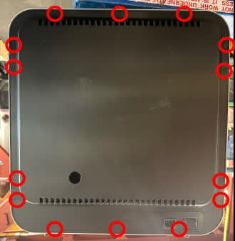
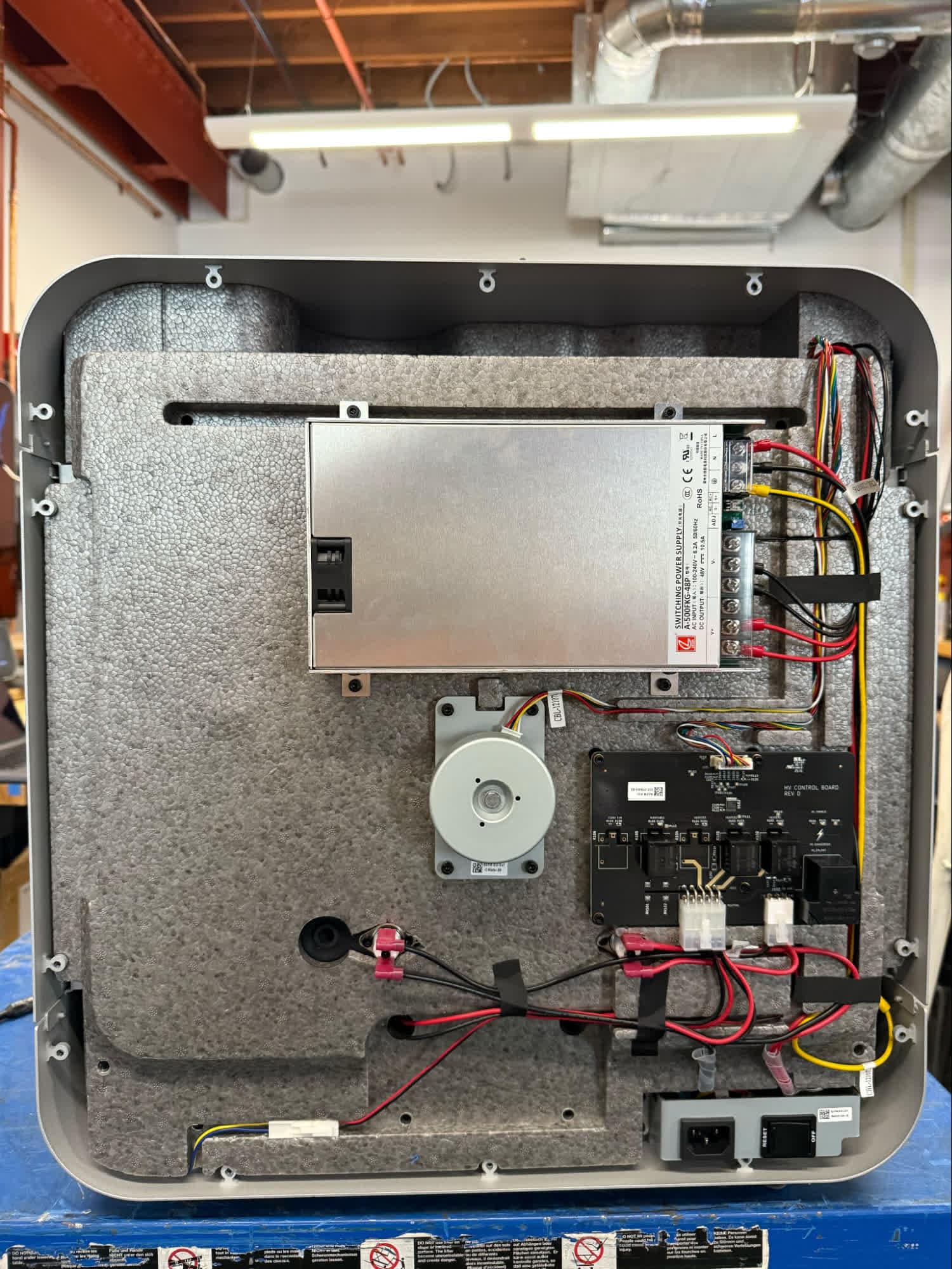
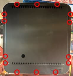
Rotate the machine so you can access its rear shell. Using a 2.5 mm hex driver, loosen and remove the 14 screws securing the rear shell to the frame of the machine. Set the screws and shell aside.
Step 2: Disconnect the cables
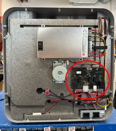
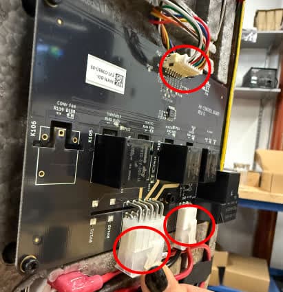
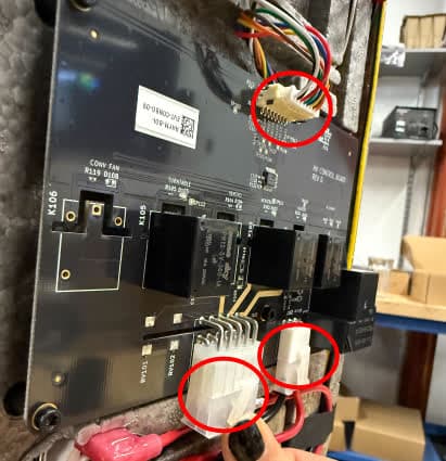
Locate the high voltage control board, positioned above the power port on the back of the machine. Disconnect the three cables from the high voltage printed circuit board assembly. For each, squeeze the tab and slide the cable out of the connector. Take care not to pull on the wires themselves.
Step 3: Remove the high voltage control board
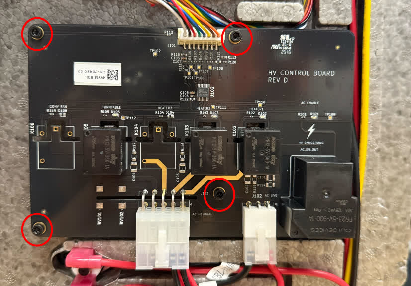
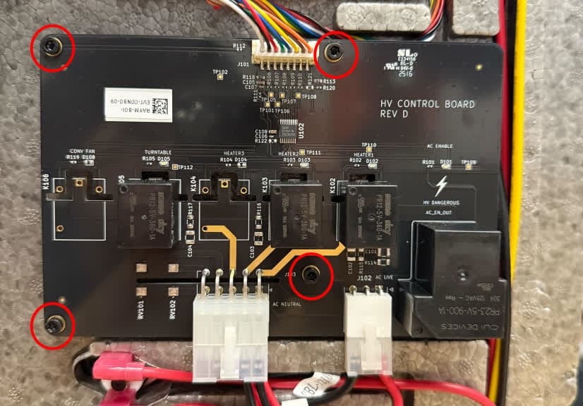
Using a 2.5 mm hex driver, loosen and remove the four screws securing the high voltage control board to the insulation panel. Set the screws and control board aside for disposal with electronic waste.
Installing the replacement high voltage control board
Overview: Connect, mount, and secure the new high voltage control board.
Step 1: Mount and secure the high voltage control board
Remove the replacement high voltage control board from its packaging. Check that each of the four standoffs on the back of the board has a washer on it. If any of the washers have fallen off during shipping, replace them.
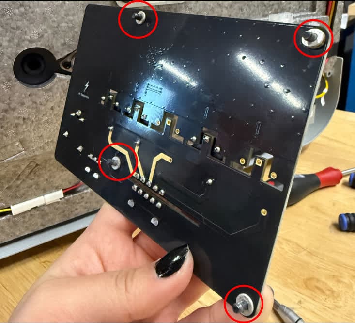
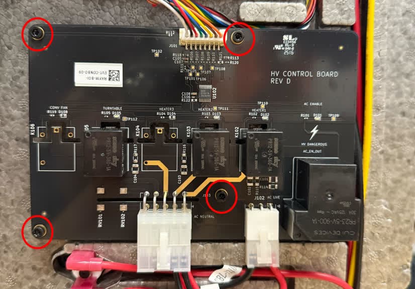
Orient the high voltage control board with the text HV CONTROL BOARD upright. Hold it against the insulation panel, aligning the four standoffs with the corresponding holes in the insulation panel. Thread one mounting screw into each of the four screw holes in the board, then use a 2.5 mm hex driver to tighten until snug.
Reconnect the three cables to the board. Each cable only fits into its connector in the correct orientation. The locking tab clicks into place when the cable is fully connected.
Mount the rear shell back onto the machine. Thread one rear shell retention screw into each of the 14 screw holes in the rear shell. Using a 2.5 mm hex driver, tighten the screws until snug.
Finalizing the repair
Overview: After installing the new high voltage control board, power on the machine and perform final checks.
Step 1: Power on the machine
Connect the power cable to the machine and its power supply. Turn on the switch at the back of the machine.
Step 2: Test the repair
Start a post-cure cycle and check that the machine reaches its target temperature and operates normally.