WHITE PAPER
Formlabs Logo

Replacing the Fuse 1+ 30W laser assembly

Replacing the Fuse 1+ 30W laser assembly

Fuse 1 generation printers use a laser to selectively sinter powder into printed parts. A faulty or malfunctioning laser assembly will lead to print failures or prevent the printer from printing entirely.

Use this guide to replace the laser assembly on a Fuse 1+ 30W printer.

Fuse 1+ 30W laser assembly

Required supplies:

Formlabs:

Third-party:

  • 2 mm hex driver (flat-end)
  • 2.5 mm hex driver (flat-end)
  • 3 mm hex driver (flat-end)
  • 6.5 mm slotted screwdriver
  • Flush cutters
  • Antistatic wrist band
  • Bulb duster
  • Kapton tape
  • Ethanol (99%, anhydrous)
  • Nonreactive nitrile gloves
  • Microfiber cloth

Estimated time: 45–60 minutes

Danger:

Read and follow all safety instructions and warnings in the operator manual. Replacement with incorrect parts can lead to burns, shock, fire, or explosion. Dispose of all parts in accordance with local regulations.

Performing this procedure may expose you to Class 4 laser radiation in the event that redundant safety systems are defeated or fail unexpectedly. Never remove any part of the laser assembly while the printer is still plugged in. Never install or use a laser assembly that is modified, damaged or otherwise unfit for use in a Fuse 1+ 30W printer.

Warning:

Do not perform this procedure if the printer was printing less than six hours prior. Failure to do so may result in serious burns. Allow the print enclosure to cool to room temperature before touching or inspecting any Fuse 1+ 30W components.

Preparing the workspace

Overview: Prepare the printer and a dust-free workspace for replacing the laser assembly.

Notice:

Fuse 1 generation printers contain sensitive electronic components. Ground yourself before touching any electronics in the printer by using a grounding strap or touching a grounded piece of metal.

Step 1: Prepare the workspace

Clear a workspace around your printer. Ensure that the workspace is well-ventilated and free of dust.

Step 2: Unplug the printer

Disconnect the power cable before continuing with maintenance. Do not perform maintenance on the printer while it is connected to power. Wait five minutes after disconnecting the printer from power before proceeding.

Danger:

Performing maintenance on the printer while it is plugged in increases the risk of electric shock. Never remove the back panel of the printer while the printer is plugged in. Never reconnect the printer to power while the back panel is uninstalled.

Step 3: Disconnect the nitrogen source

Disconnect the nitrogen hose from the quick-disconnect fitting, if connected.

Step 4: Remove the Wi-Fi antenna

Unscrew and remove the Wi-Fi antenna, if it is connected.

Removing the rear panels

Overview: Remove the rear panels to access the interior of the printer.

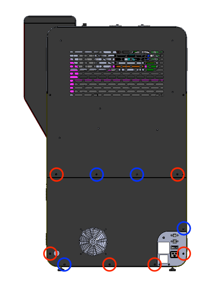
Step 1: Remove the lower rear panel screws

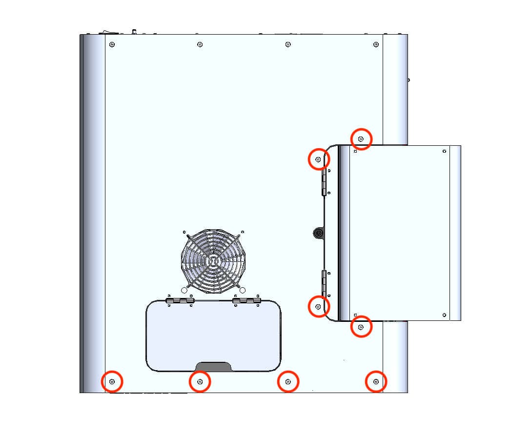
The six black lower rear panel screws are circled in red. The four chrome lower rear panel grounding screws are circled in blue.

Using a 2.5 mm hex driver, remove the six black panel screws and the four chrome panel grounding screws securing the lower rear panel to the printer. Set the screws aside, taking care to separate the black and chrome screws for later reinstallation.

Step 2: Remove the lower rear panel from the printer

Pull the lower rear panel straight back and away from the printer. Lay it down on a flat, clean surface.

Step 1: Remove the lower rear panel screws

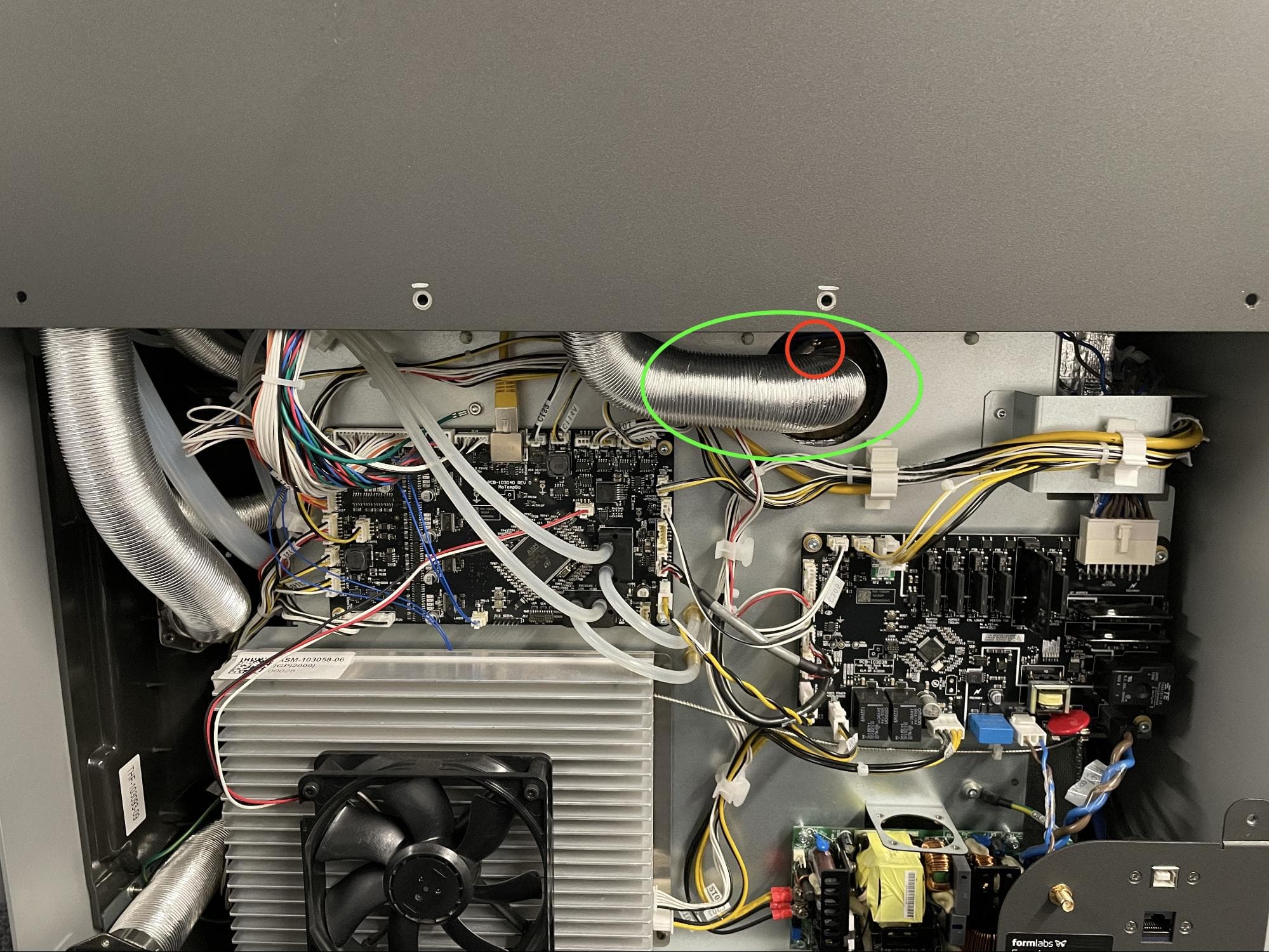
Step 3: Locate the exhaust duct and ring clamp

Locate the ring clamp attached to the exhaust duct in the center of the printer.

Step 4: Loosen the ring clamp screw

Using a 6.5 mm flathead screwdriver, loosen the ring clamp screw. Do not remove the screw. Pull the exhaust duct away from the exhaust pipe.

Step 3: Locate the exhaust duct and ring clamp

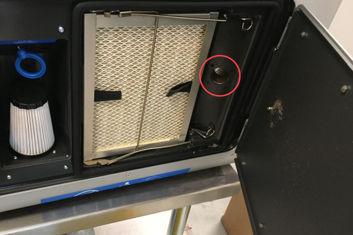
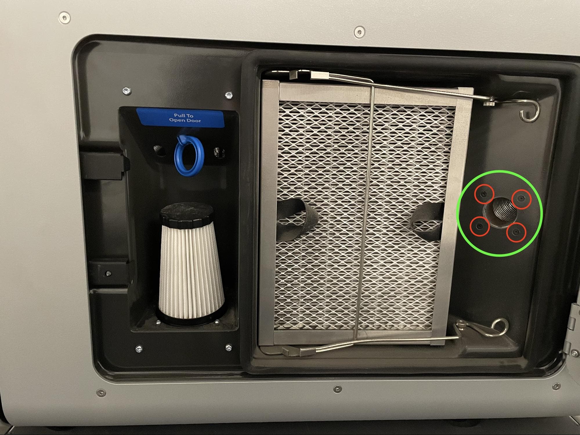
Step 5: Locate the exhaust inlet

Open the filter cabinet door on the printer. Locate the exhaust inlet on the right side of the cabinet.

Step 5: Locate the exhaust inlet

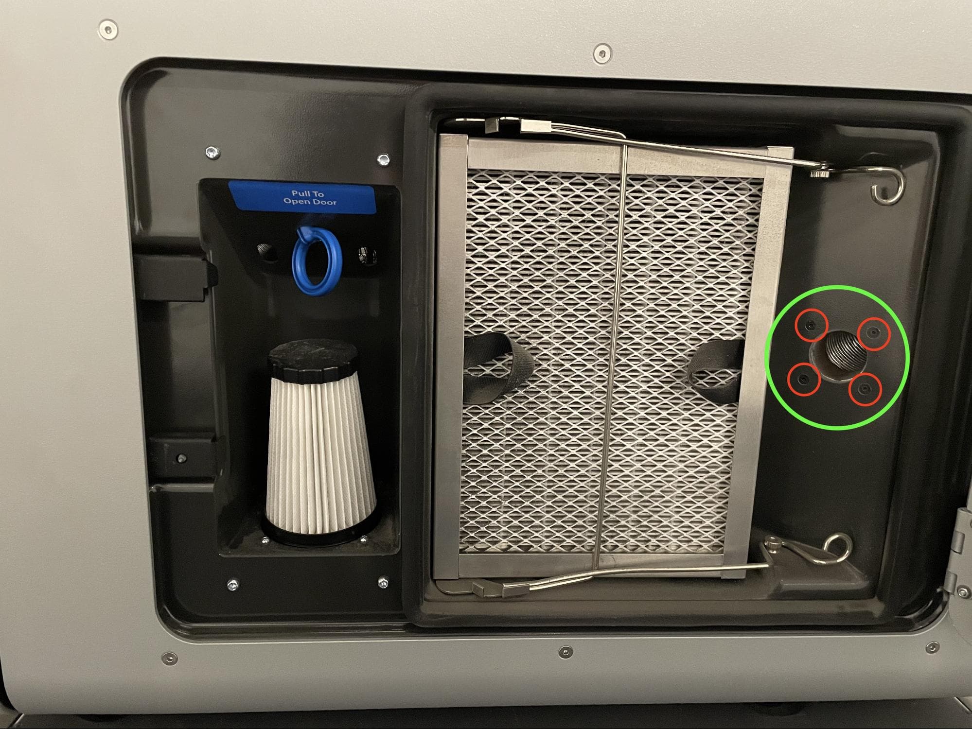
Step 6: Remove the exhaust inlet screws

Using a 2.0 mm hex driver, remove the four screws attaching the exhaust inlet to the filter cabinet. Set the screws aside.

Step 6: Remove the exhaust inlet screws

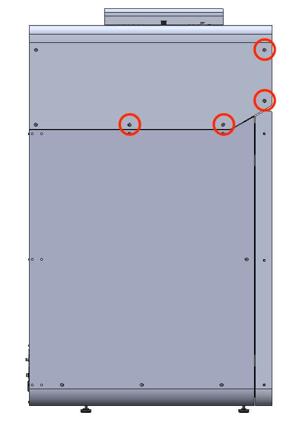
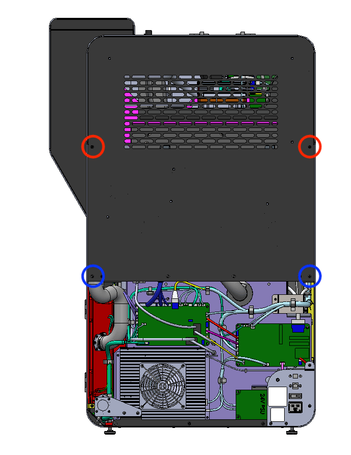
Step 7: Remove the upper rear panel screws

The two black upper rear panel screws are circled in red. The two chrome upper rear panel grounding screws are circled in blue.

Using a 2.5 mm hex driver, remove the two black panel screws and two chrome panel grounding screws securing the upper rear panel to the printer. Set the screws aside, taking care to separate the black and chrome screws for later reinstallation.

Step 7: Remove the upper rear panel screws

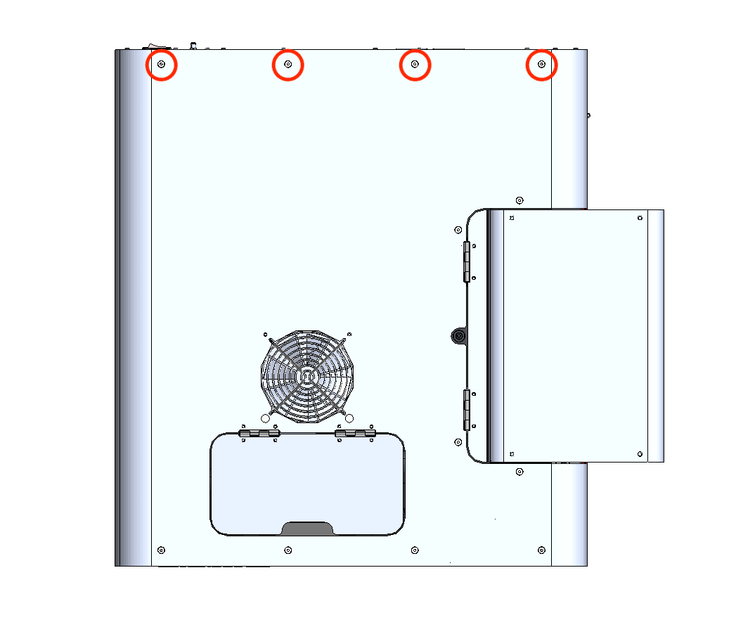
Step 8: Remove the upper rear panel screws

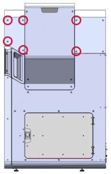
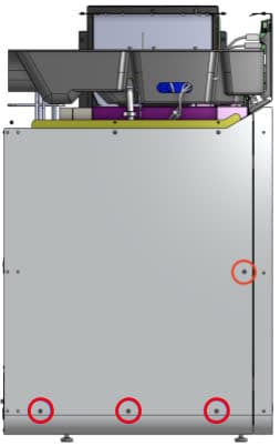
Using a 2.5 mm hex driver, remove the eight screws securing the upper rear panel to the printer:

Step 8: Remove the upper rear panel screws
  • Two 6 mm screws on the buffer side of the printer
  • Four 6 mm screws on the top of the printer
  • Two 6 mm screws on the hopper side of the printer

Set the screws aside.

Step 9: Remove the upper rear panel

Pull the upper rear panel straight back and away from the printer. Lay it down on a flat, clean surface.

Removing the top panel

Overview: Remove the top panel to access the interior of the printer.

Step 1: Remove the top panel screws

Using a 2.5 mm hex driver, remove the 18 6 mm M4 countersunk screws securing the top panel to the printer:

Remove the top enclosure panel
  • Four 6 mm screws on the front end of the buffer-side
  • Eight 6 mm screws on top of the printer
  • Six 6 mm screws on the hopper-side

Set the screws aside.

Step 2: Remove the top panel

Lift the top panel off of the printer by grabbing the IR sensor door and the rear-most edge. Set the top panel aside.

Removing the buffer-side panel

Overview: Remove the buffer-side panel to access the interior of the printer.

Step 1: Remove the buffer-side panel screws

Using a 2.5 mm hex driver, remove the four 6 mm M4 countersunk screws that secure the buffer-side panel to the printer.

Step 2: Remove the buffer-side panel

Separate the buffer-side panel from the printer and set it aside.

Remove the buffer-side enclosure panel

Removing the upper cooling shroud

Overview: Remove the upper cooling shroud to access the laser collimator and lens.

Step 1: Remove the IR sensor

Removing the IR sensor

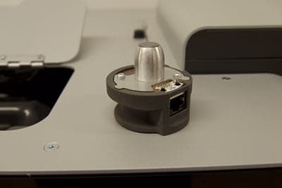
Open the access door to the IR sensor panel, located on top of the printer next to the hopper. Lift the IR sensor and disconnect the cable from it. Set the IR sensor aside on a flat surface with the sensor window facing up. Feed the IR sensor’s cable down through the plastic shroud.

Step 2: Remove the upper cooling shroud mounting screws

Using a 3 mm hex driver, loosen and remove the four 8 mm M4 socket head screws securing the upper cooling shroud to the printer. Newer printers also include four washers. Set the screws and washers (if present) aside. Do not separate the upper cooling shroud from the printer at this time.

Remove the top cooling shroud

Step 3: Disconnect the nitrogen valve cable, nitrogen pressure sensor cable, and cooling fan cable

Remove the top cooling shroud

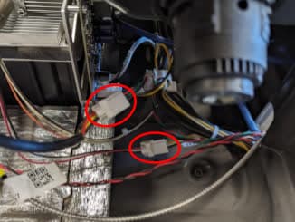
Disconnect the nitrogen solenoid valve from the cable labeled F1+ Nitro N2 Valve Cable. Disconnect the nitrogen pressure sensor from the cable labeled F1+ Nitro Pressure Sensor Cable. Disconnect the cooling fan from cable C047.

For each, disconnect the cable by opening the tab and pulling the plastic connectors apart. Do not pull on the wires themselves.

Step 4: Disconnect the tubing from the upper cooling shroud

Remove the top cooling shroud

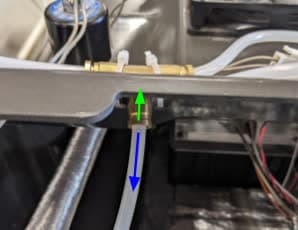
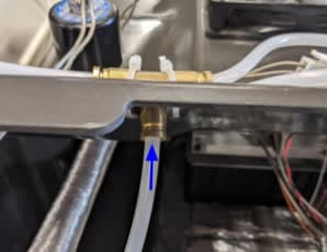
Locate the brass tee fitting on the rear side of the cooling shroud. Push the brass ring down while pulling on the plastic tube to disconnect it.

Locate the brass elbow fitting towards the rear hopper side of the printer. Push the brass ring down while pulling on the plastic tube to disconnect it.

To avoid confusing the tubes, use a permanent marker or piece of tape to label them.

Step 5: Separate the upper cooling shroud from the printer

Gently lift the shroud up and away from the printer. Check that all cables and tubes have been disconnected and nothing is caught or tangled. Remove the shroud from the printer and set it aside.

Removing the original laser assembly

Overview: Unplug and remove the original laser assembly.

Step 1: Prepare to remove the laser assembly

Put on an antistatic wrist band and connect it to a known ground point. Do not connect the wristband any surfaces that are powder-coated or painted.

Put on a pair of clean nitrile gloves.

Step 2: Unmount the nitrogen intake panel

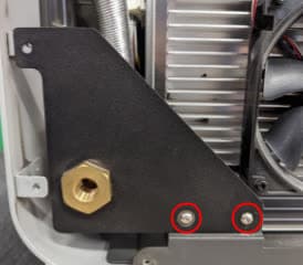
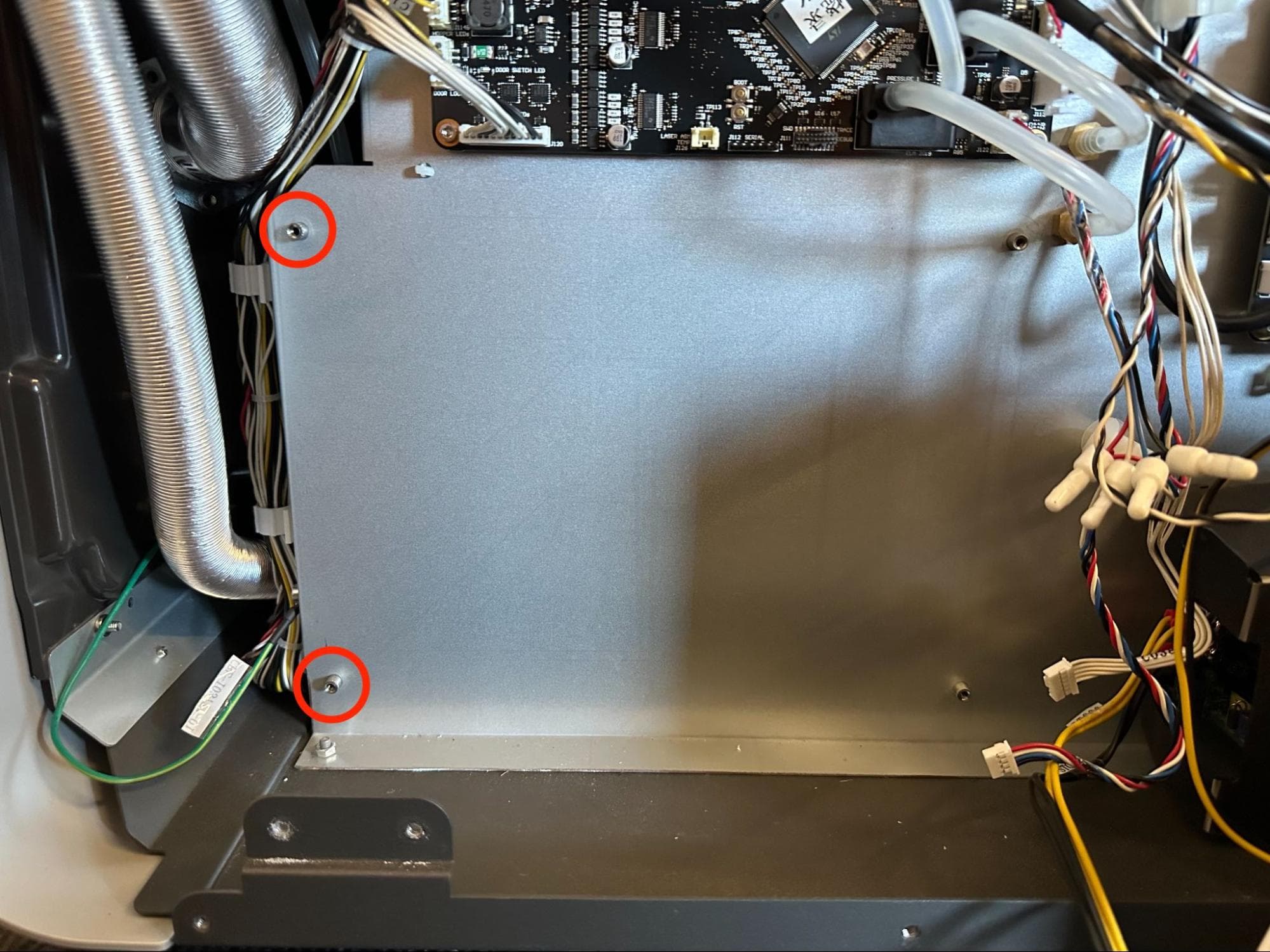
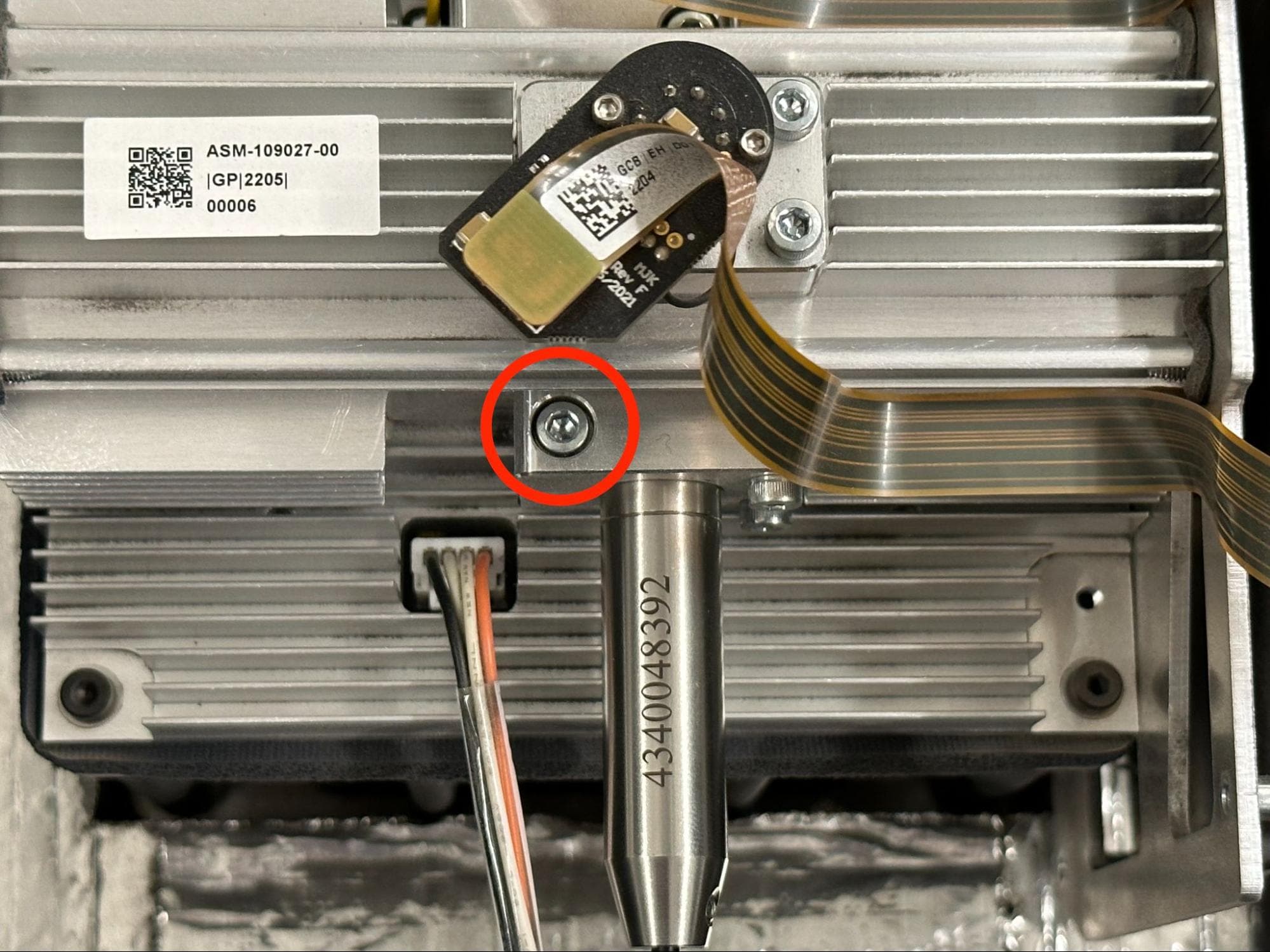
The nitrogen intake panel, located at the bottom-left corner of the back of the printer, is secured to the printed by two or three 6 mm M4 button head screws, depending on the age of your printer. Using a 2.5 mm hex driver, loosen and remove these screws. Set the screws aside and move the nitrogen intake panel away from the laser assembly heatsink.

Remove the original laser assembly

Step 3: Unplug the cables from the laser assembly

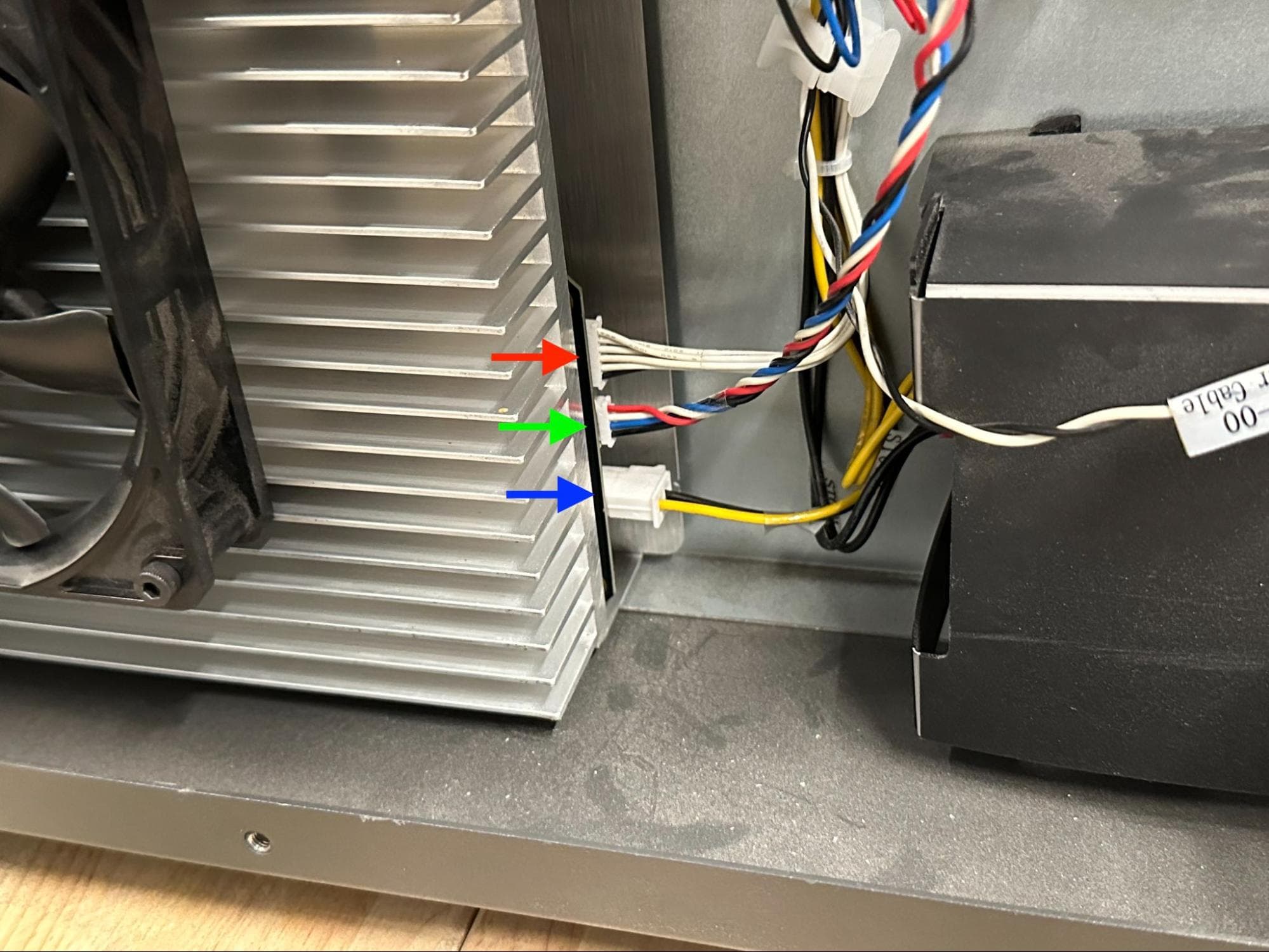
Disconnect the three connectors on the right-hand side of the laser assembly, labeled C054, J092, and C038.

Remove the original laser assembly

Step 4: Disconnect the laser cooling fan and temperature sensor cables

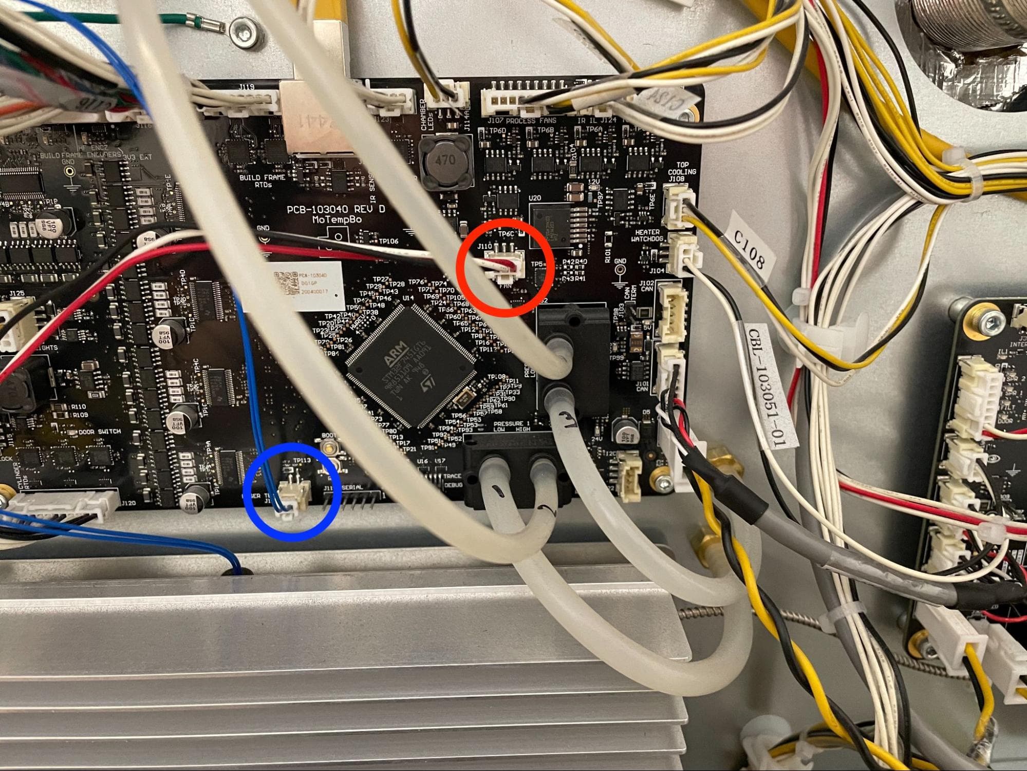
Disconnect the laser cooling fan and temperature sensor cables from the motor and temperature board just above the laser assembly.

Remove the original laser assembly

Step 5: Disengage the laser fiber clips

Starting at the rear of the printer, disengage the laser fiber from the 11 plastic clips it is routed through.

Remove the original laser assembly

Step 6: Separate the laser collimator from the galvo block

At the top of the printer, locate the M3 socket head screw securing the laser collimator to the galvo block. Using a 2.5 mm hex driver, loosen but do not remove the screw. Gently pull the collimator out of the galvo block.

Remove the original laser assembly

Step 7: Protect the laser collimator and galvo block

Remove the original laser assembly

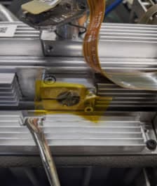
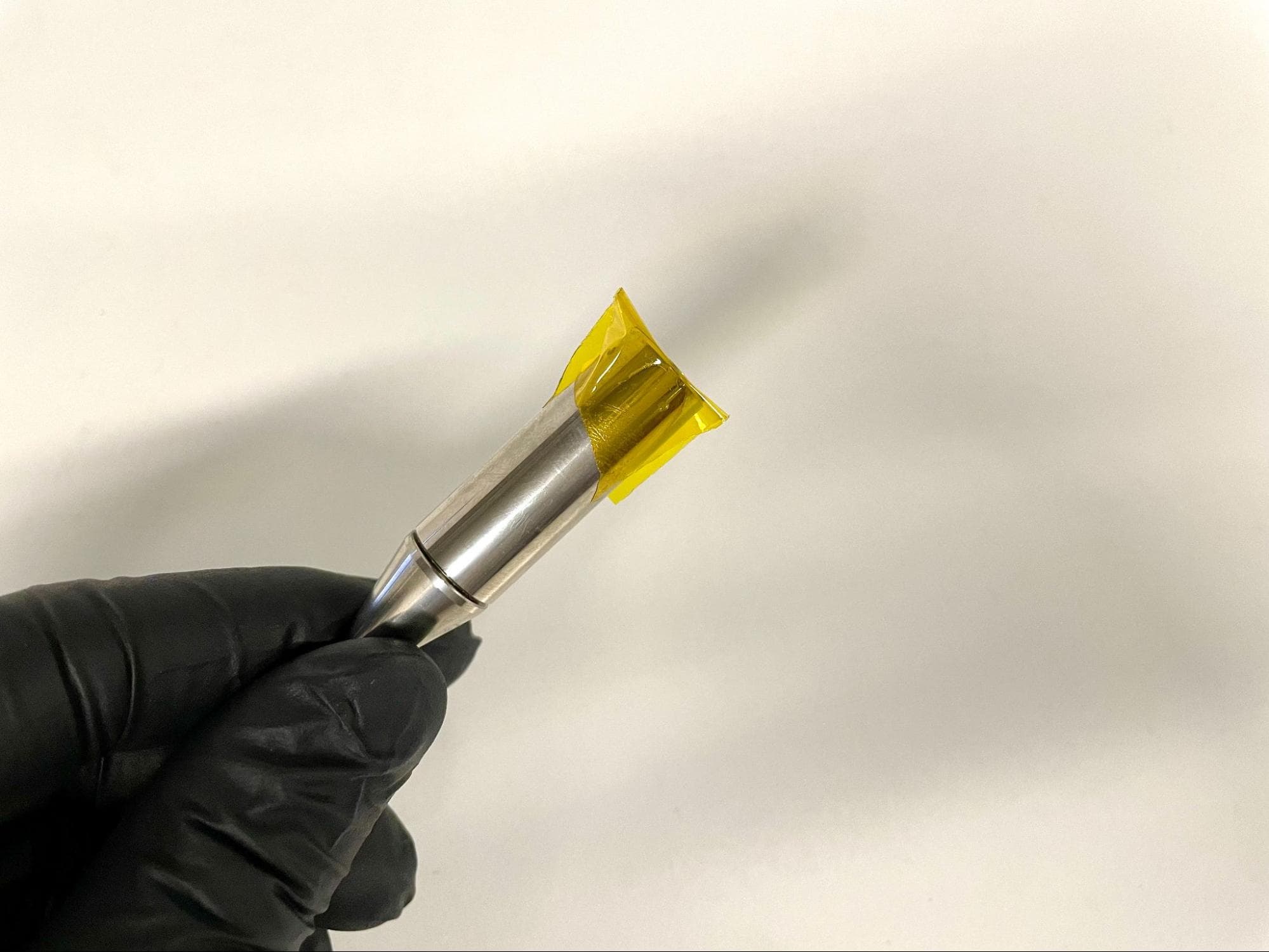
Apply a piece of kapton tape to the lens so that it also wraps around the collimator. Apply a second piece of kapton tape to the hole from where the collimator was removed to prevent dust from entering the galvo block.

Remove the original laser assembly

Step 8: Separate the collimator from the printer

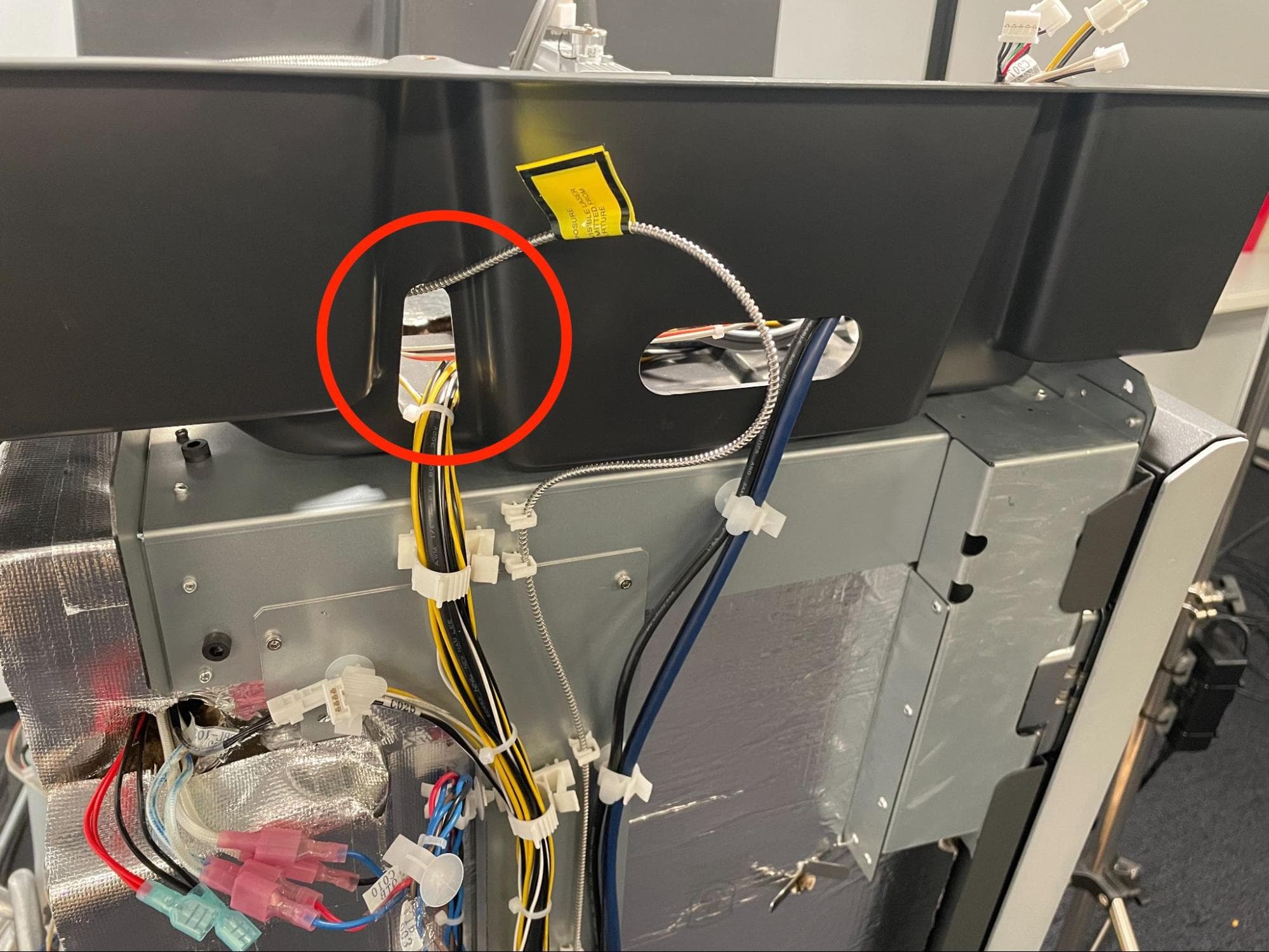
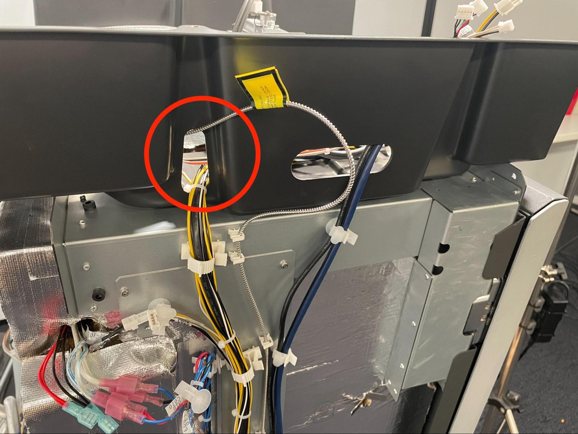
Feed the collimator and fiber through the cutout in the plastic shroud.

Step 9: Identify the laser assembly type

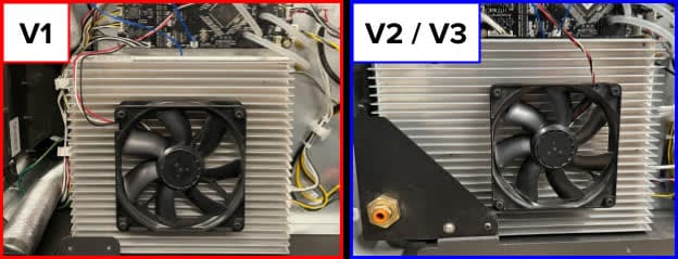
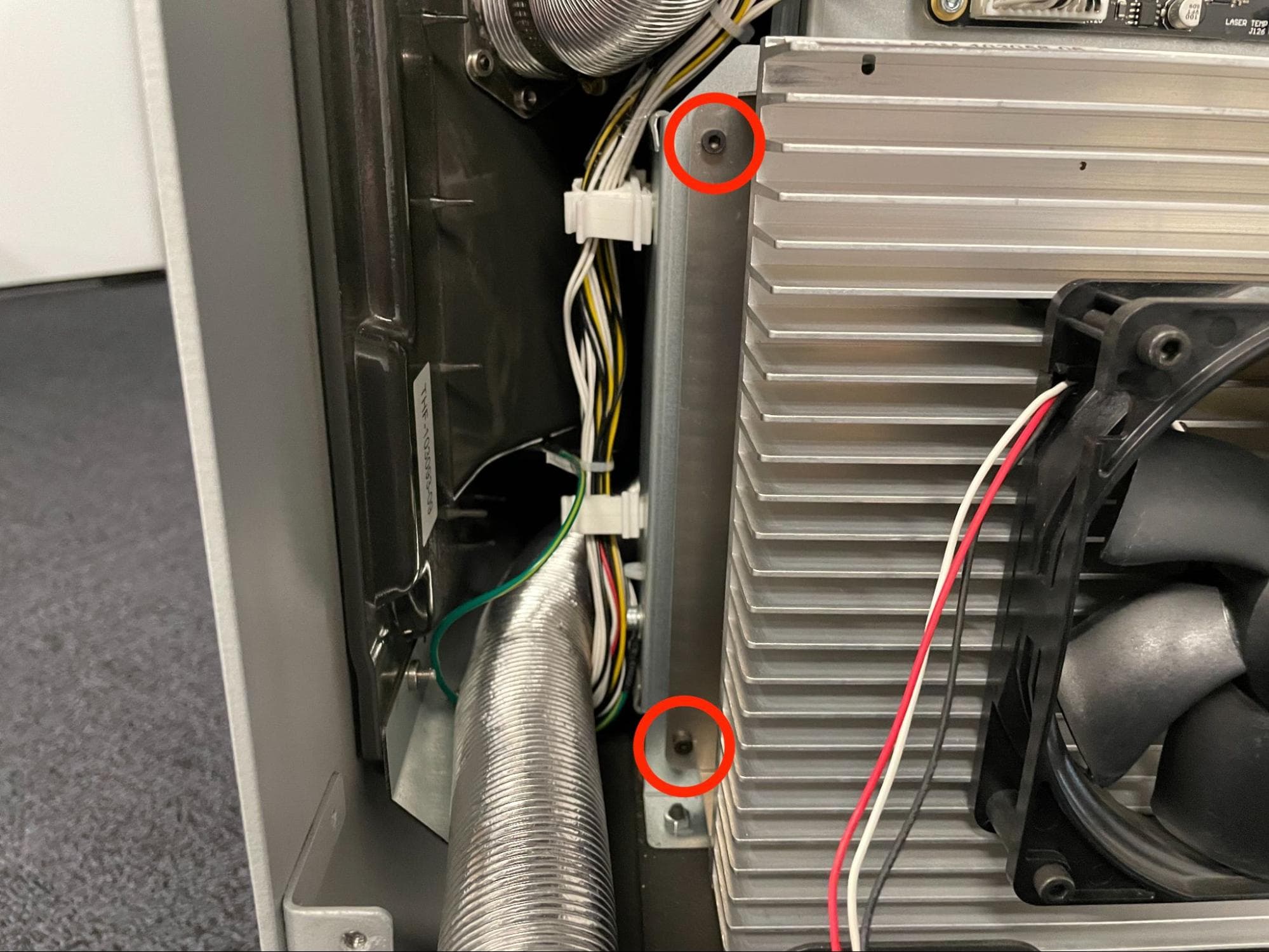
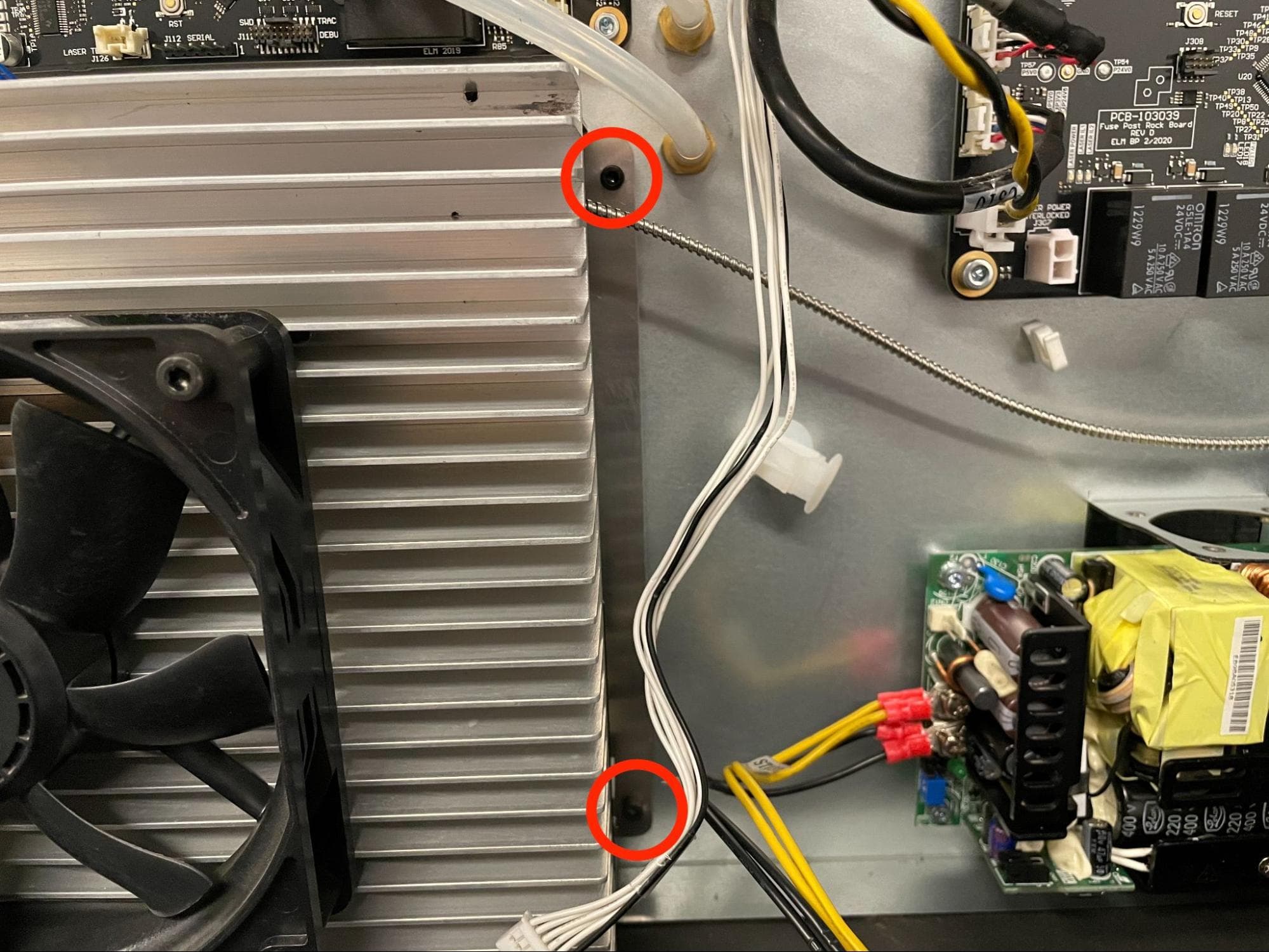
There are two variants of Fuse 1+ 30W laser assemblies, each of which has a different mounting method. If the assembly matches the V1 design shown here, with a narrower heatsink, proceed to step 10. If it matches the V2/V3 design, with a wider heatsink, proceed to step 46.

Remove the original laser assembly

Step 10: Remove the laser assembly mounting screws (V1 only)

Remove the original laser assembly

Using a 2.5 mm hex driver, loosen and remove the four 12 mm M3 socket head screws securing the laser assembly to the printer. Proceed to step 12.

Step 11: Remove the laser assembly mounting screws (V2/V3 only)

Remove the original laser assembly

Using a 2.5 mm hex driver, loosen but do not remove the two 12 mm M3 socket head screws securing the left side of the laser assembly to the printer.

Using a 2.5 mm hex driver, loosen and remove the two 12 mm M3 socket head screws securing the right side of the laser assembly to the printer. Proceed to step 12.

Slide the laser assembly to the left to free it.

Step 12: Remove the laser assembly

Carefully pull the original laser assembly out of the printer and set it aside for disposal with electronic waste.

Installing the replacement laser assembly

Overview: Connect, mount, and secure the replacement laser assembly. Route the laser fiber and mount the collimator in the galvo block.

Step 1: Prepare to install the new laser assembly

If you are not still wearing one, put on an antistatic wrist band and connect it to a known ground point. Put on a pair of clean nitrile gloves.

Remove the new laser assembly from its packaging. Before installing, ensure that the lens is free of scratches, smudges, dust, and debris. Use a bulb blower to clear any dust. If any contamination remains on the lens, gently wipe it off using a microfiber cloth wetted with ethanol.

Cover the lens with a new piece of kapton tape until it is time to insert the collimator into the galvo block.

Install the new laser assembly

Step 2: Prepare the laser assembly mount

If you originally had a V1 laser assembly, partially thread (by roughly three complete turns) a 12 mm M3 socket head screw into the two leftmost laser mounting standoffs. If you originally had a V2 or V3 laser, these screws should still be installed.

Install the new laser assembly

Step 3: Mount the laser assembly

Install the new laser assembly

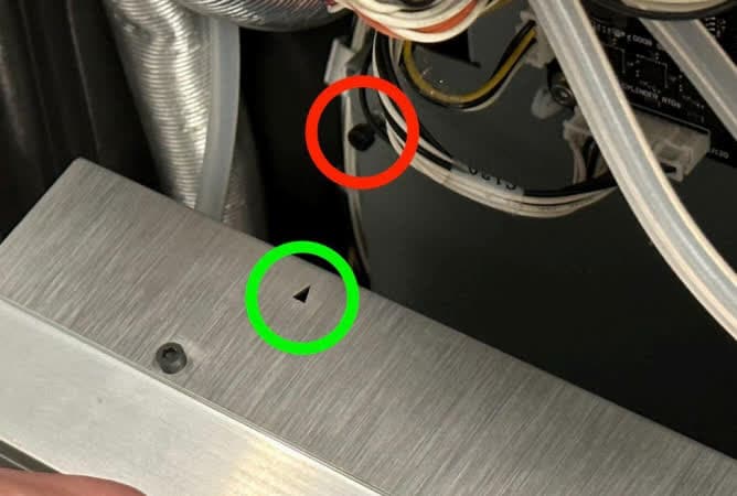
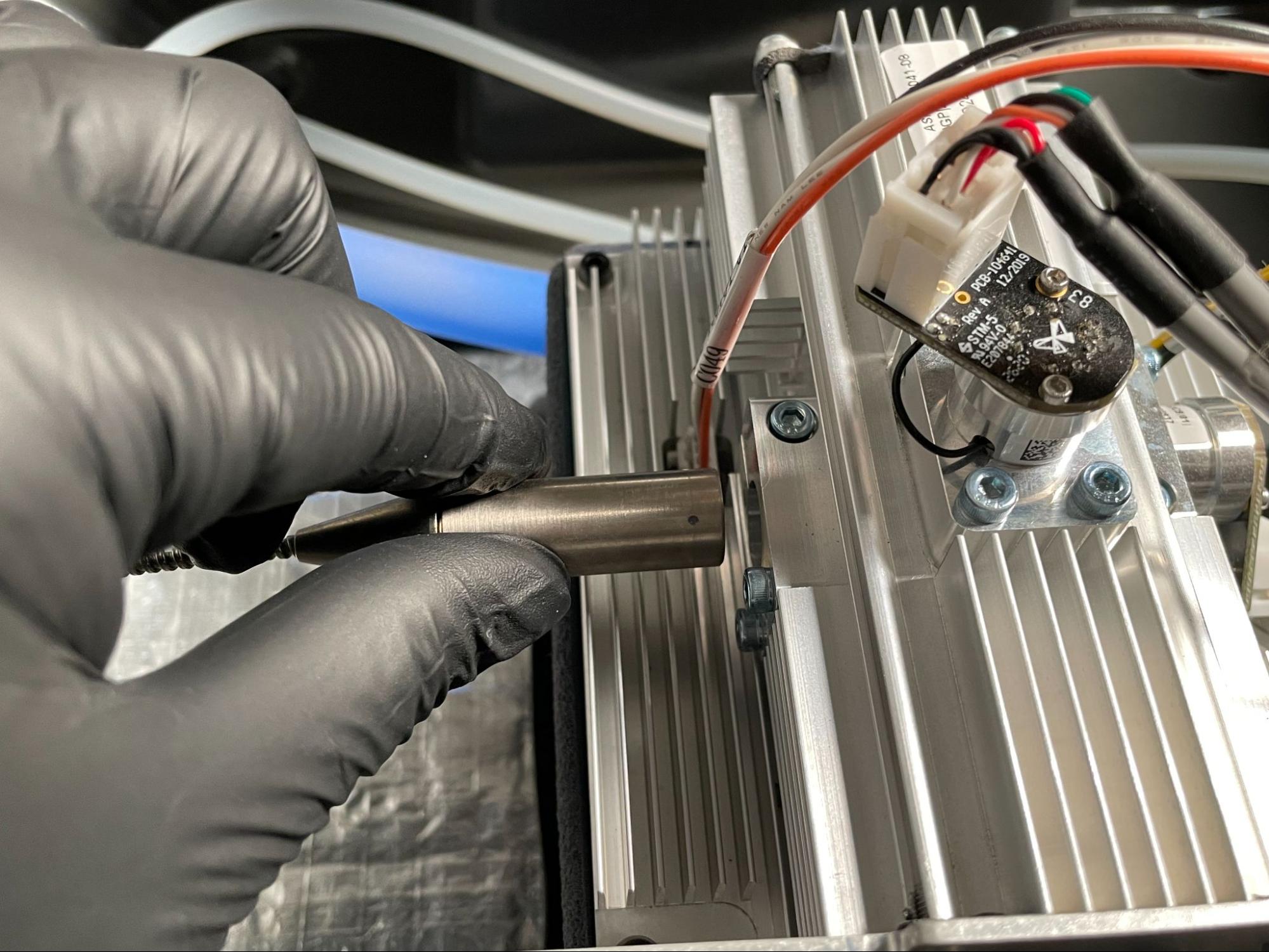
Bring the laser assembly up to the printer and align the arrow with the top partially-threaded M3 screw.

Tilt the laser assembly into place. Once both the top and bottom screws have engaged the keyholes in the laser assembly, slide the assembly to the right.
Step 4: Secure the laser assembly

Install the new laser assembly

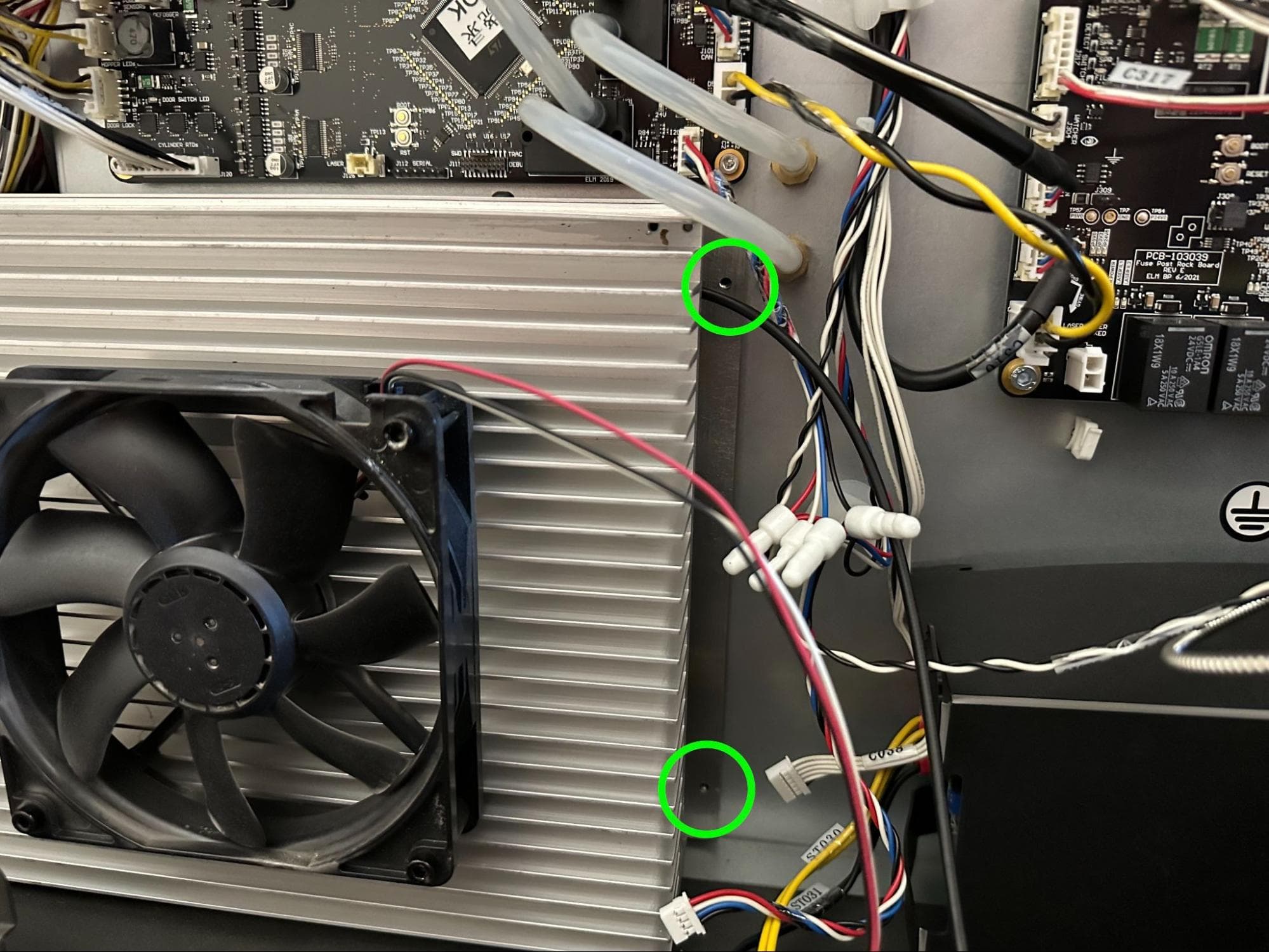
Thread one 12 mm M3 socket head screw into both of the rightmost screw holes in the laser assembly. Using a 2.5 mm hex driver, tighten until snug.
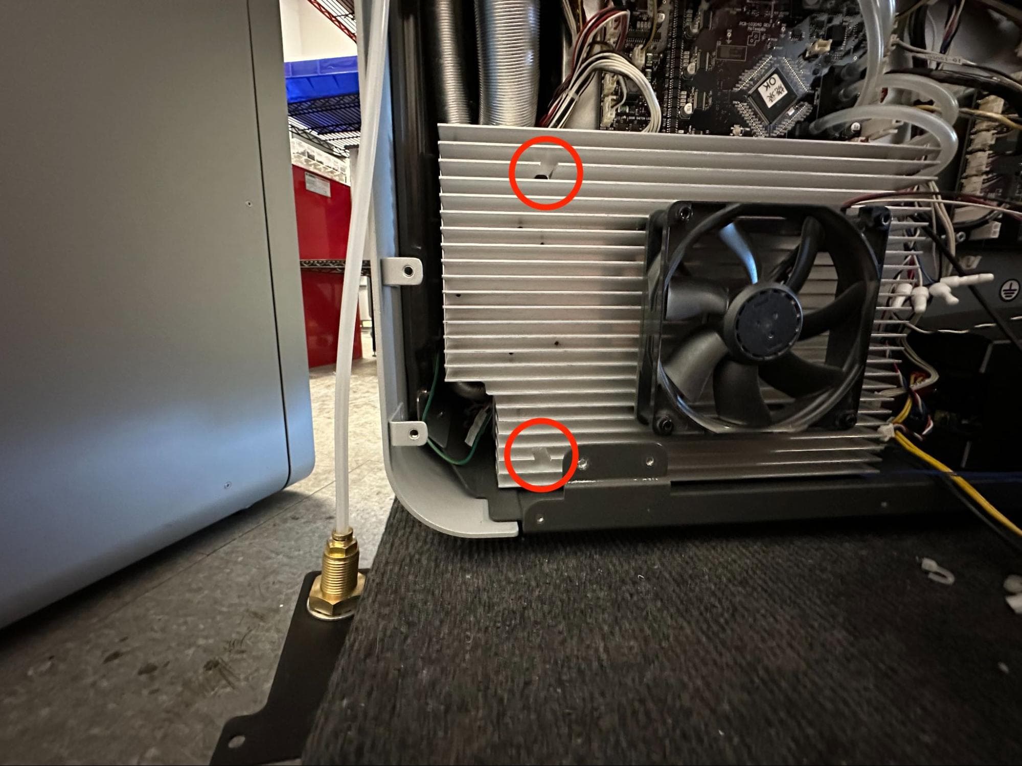
Use a 2.5 mm hex driver to fully secure the leftmost 12 mm M3 socket head screws that were left partially unthreaded. Access the screws using the holes in the heatsink.

Install the new laser assembly

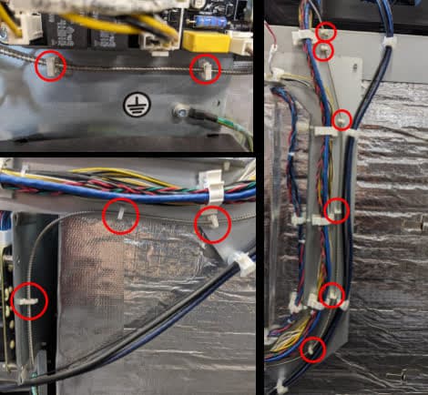
Reroute the laser fiber from the rear to the top of the printer and secure using the 11 plastic clips. Ensure that the fiber has no slack and there are no sharp bends or kinks.

Feed the collimator through the slot in the plastic cooling shroud.
Step 6: Mount the collimator

Install the new laser assembly

Remove the kapton tape from the collimator and verify that the lens is clean. Remove the kapton tape covering the hole in the galvo block.

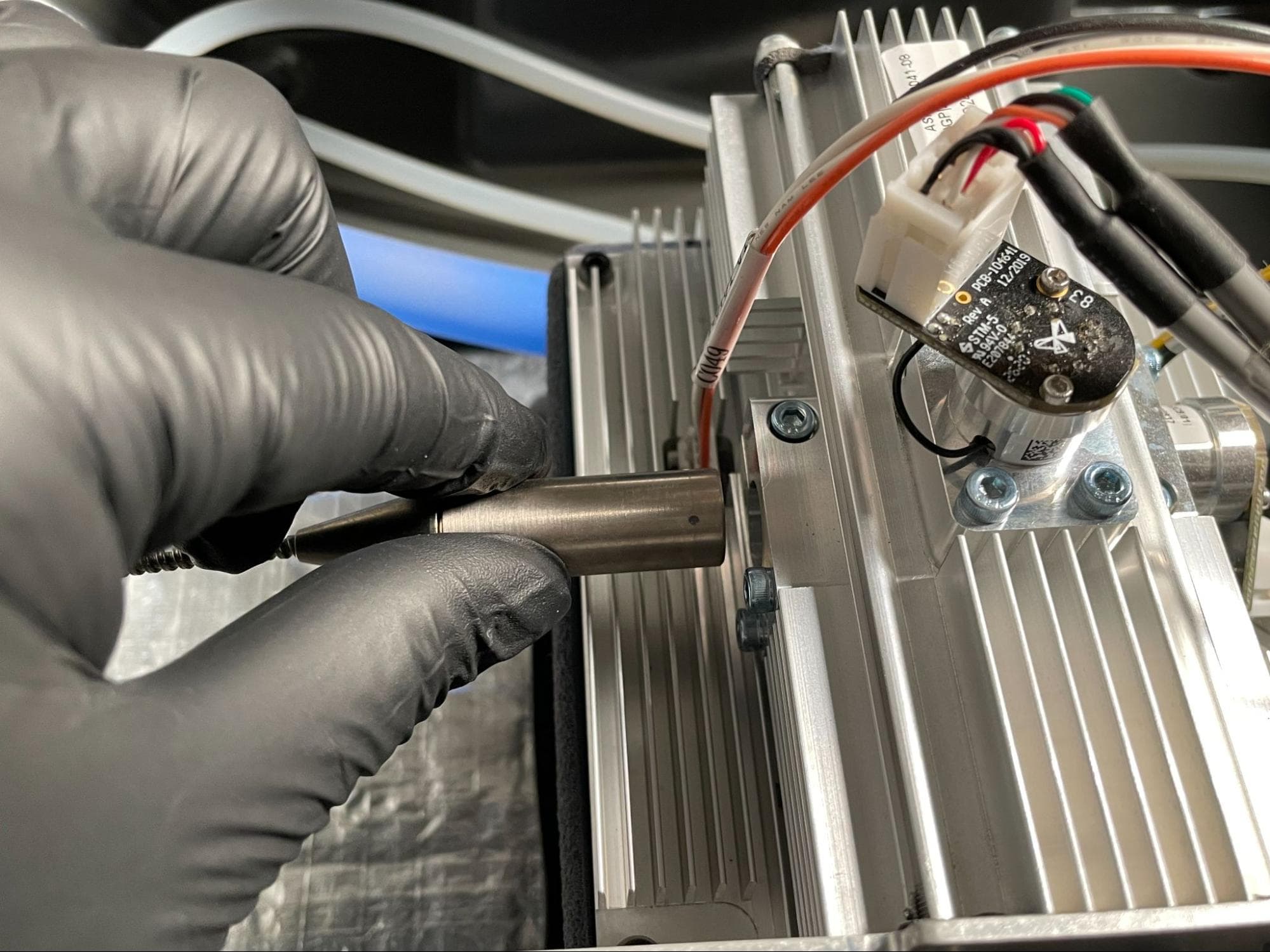
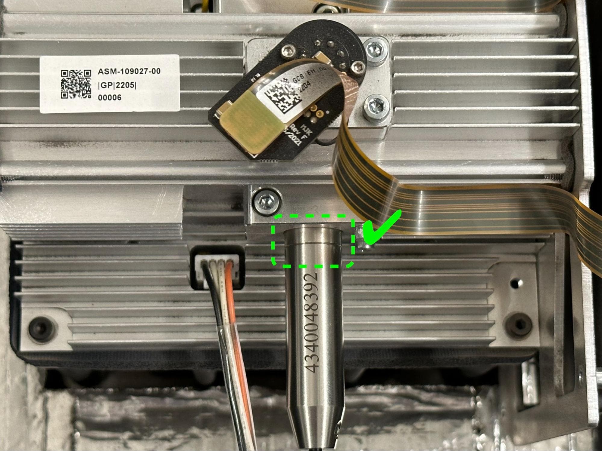
Gently insert the collimator into the galvo block until it reaches a hard stop and cannot be inserted any farther.

Step 7: Secure the collimator

Using a 2.5 mm hex driver, tighten the M3 socket head screw next to the collimator until it is snug.

Install the new laser assembly

Step 8: Reconnect the laser cables

Install the new laser assembly

Reconnect the three connectors labeled C054, J092, and C038 to the right-hand side of the laser assembly. Reconnect the laser cooling fan and temperature sensor cables to the motor and temperature controller board above the laser assembly. Each connector only fits in the appropriate receptacle in one orientation.

Step 9: Mount and secure the nitrogen intake panel

Place the nitrogen intake panel back on its mounting points, aligning the screw holes in the panel with the corresponding holes in the printer frame. Thread one 6 mm M4 button head screw into each of the two or three screw holes, depending on the age of your printer. Using a 2.5 mm hex driver, tighten the screws until snug.

Install the new laser assembly

Reinstalling the upper cooling shroud

Overview: After replacing the laser assembly, reinstall the upper cooling shroud.

Step 1: Reconnect the upper cooling shroud cables

Replace the top cooling shroud

Reconnect the cooling fan connector to the socket labeled C047. Reconnect the solenoid valve to the cable labeled F1+ Nitro N2 Valve Cable. Reconnect the N2 pressure sensor to the cable labeled F1+ Nitro Pressure Sensor Cable.

Step 2: Route the IR sensor cable

Position the top cooling shroud by holding it from the front edge so that the cables covered by the shroud can still be accessed. Feed the IR sensor’s Ethernet cable back through the cutout in the top shroud.

Step 3: Mount the upper cooling shroud

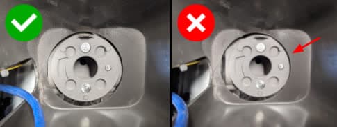
Lower the upper cooling shroud on the printer, aligning the four screw holes in the shroud with the corresponding screw holes in the printer frame. Ensure the shroud is positioned so that there is a uniform gap around the IR sensor flow body. If there is overlap, the IR sensor will not fit correctly.

Replace the top cooling shroud

Step 4: Secure the upper cooling shroud

Thread one 8 mm M4 socket head screw into each of the screw holes in the upper cooling shroud. Using a 3 mm hex driver, tighten until snug.

Replace the top cooling shroud

Step 5: Route the nitrogen solenoid valve tubing

Tuck the plastic tube connected to the nitrogen solenoid valve under the sheet metal hopper cover as shown.

Replace the top cooling shroud

Step 6: Reconnect the tubing to the upper cooling shroud

Replace the top cooling shroud

Locate the brass tee fitting on the rear side of the cooling shroud. Push the plastic tube firmly into the fitting.

Locate the brass elbow fitting towards the rear hopper side of the printer. Push the plastic tube firmly into the fitting.

After insertion, pull on the tubes gently to ensure they do not come out.

Step 7: Connect and mount the IR sensor

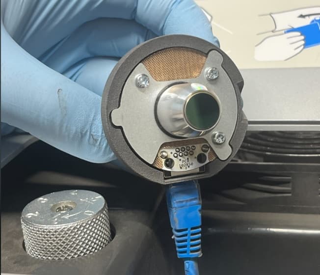
Inspect the IR sensor lens for debris and clean it if necessary. Attach the ethernet cable to the IR sensor, then place the sensor back into its mount.

Replace the top cooling shroud

Reinstalling the buffer-side panel

Overview: After installing the replacement laser assembly, reinstall and secure the buffer-side panel.

Step 1: Align the buffer-side panel with the printer

Lift the buffer-side panel and align its screw holes with those in the printer frame, as shown.

Step 2: Secure the buffer-side panel

Thread one 6 mm M4 countersunk screw into each of the four marked screw holes in the buffer-side panel. Using a 2.5 mm hex driver, tighten until snug.

Remove the buffer-side enclosure panel

Reinstalling the top panel

Overview: After reinstalling the buffer-side panel, reinstall and secure the top panel.

Step 1: Align the top panel

Lift the top panel and place it on top of the printer. Align the screw holes in the top panel with the corresponding holes in the printer frame.

Step 2: Secure the top panel screws

Thread a 6 mm M4 countersunk screw into each of the 18 marked screw holes in the top panel:

Remove the top enclosure panel
  • Four 6 mm screws on the front end of the buffer-side
  • Eight 6 mm screws on top of the printer
  • Six 6 mm screws on the hopper-side

Using a 2.5 mm hex driver, tighten the screws until snug.

Reinstalling the rear panels

Overview: After installing the replacement laser assembly, reinstall and secure the rear panels.

Step 1: Align the upper rear panel with the printer

Lift the upper rear panel and align it with the four screw holes on the top of the printer.

Step 2: Secure the upper rear panel top screws

Thread the four 6.0 mm screws into each of the screw holes on the top of the printer. Using a 2.5 mm hex driver, tighten the screws until finger tight. You may need to adjust the exhaust duct to correctly position the upper rear panel.

Step 1: Align the upper rear panel with the printer

Step 3: Secure the buffer side panel screws

Thread the two 6 mm screws into the screw holes on the buffer side and the two 6 mm screws into the screw holes on the hopper side. Using a 2.5 mm hex driver, tighten the screws until snug.

Step 3: Secure the buffer side panel screws

Step 4: Secure the hopper side panel screws

Thread the two 6mm screws into the holes on the hopper side. Using a 2.5 mm hex driver, tighten the screws until snug.

Step 4: Secure the hopper side panel screws

Step 5: Secure the upper rear panel grounding screws

The two black upper rear panel screws are circled in red. The two chrome upper rear panel grounding screws are circled in blue.

Thread the panel screws into the indicated screw holes on the upper rear panel. Refer to the image for the correct locations of the black and chrome screws. Using a 2.5 mm hex driver, screw in the two black panel screws and two chrome grounding screws securing the upper rear panel to the printer.

Step 5: Secure the upper rear panel grounding screws

Notice:

The placement of the chrome screws is critical to the printer's electrical grounding. Incorrect placement may lead to printer damage.

Step 6: Slide the exhaust duct into position

Step 6: Slide the exhaust duct into position

Slide the end of the exhaust duct with the ring clamp back onto the exhaust pipe. Ensure the exhaust duct presses against the insulation panel.

Step 7: Tighten the exhaust duct ring clamp

Using a 6.5 mm flathead screwdriver, tighten the ring clamp until finger tight.

Step 8: Secure the exhaust inlet screws

Open the filter cabinet door on the printer. Thread the four 8.0 mm screws into the screw holes. Using a 2.0 mm hex driver, screw in the four exhaust duct screws until finger tight.

Step 9: Check the exhaust duct seal

To ensure there is no gap between the exhaust duct’s mounting plate and the filter cabinet housing, shine a flashlight or other light source around the exhaust inlet inside the filter cabinet. If any light is visible behind the filter cabinet, the duct is not properly sealed. If necessary, use a 2.0 mm hex driver to tighten the exhaust duct screws. Close the filter cabinet door when finished.

Step 8: Secure the exhaust inlet screws

Step 10: Secure the lower rear panel grounding screws

The six black lower rear panel screws are circled in red. The four chrome lower rear panel grounding screws are circled in blue.

Thread the panel screws into the indicated screw holes on the lower rear panel. Refer to the image for the correct locations of the black and chrome screws. Using a 2.5 mm hex driver, screw in the six black panel screws and four chrome panel grounding screws securing the lower rear panel to the printer.

Step 1: Remove the lower rear panel screws

Notice:

The placement of the chrome screws is critical to the printer's electrical grounding. Incorrect placement may lead to printer damage.

Step 11: Reinstall the Wi-Fi antenna (optional)

Screw the Wi-Fi antenna onto the jack on the back of the unit.

Step 12: Reconnect the nitrogen supply (optional)

Reconnect the nitrogen hose to the quick-disconnect fitting, if previously installed.

Finalizing the repair

Overview: After installing the replacement laser assembly, power on the printer and perform final checks.

Step 1: Power on the printer

Connect the power cable to the printer and the power supply. The printer initializes.

Step 2: Test the repair

Start a print. Monitor the printer to ensure that the print proceeds normally. Contact Formlabs Support or your certified service provider to share the results of the procedure.