WHITE PAPER
Formlabs Logo

Replacing the Fuse 1 generation upper laser window

Replacing the Fuse 1 generation upper laser window

The upper laser window is part of the optical path in Fuse 1 generation printers and protects the laser collimator, lens, and galvanometers from contamination. A damaged upper laser window may lead to print failures or other unexpected issues.

Use this guide to replace the upper laser window in a Fuse 1 generation printer.

Fuse 1 generation upper laser window

Required supplies:

Formlabs:

Third-party:

  • 2.5 mm hex driver (flat-end)
  • 3 mm hex driver (flat-end)
  • Telescoping backlit mirror
  • Antistatic wrist band
  • Bulb duster
  • Compliant vacuum with static dissipative components, such as a Class II, Division 2 vacuum
  • Appropriate personal protective equipment (PPE) for handling the powder in the printer
  • Nonreactive nitrile gloves (at least three pairs)
  • Polyester swabs (included with Fuse 1 generation printers)
  • Optical cleaning cloths (included with Fuse 1 generation printers)
  • Ethanol (99%, anhydrous) or isopropyl alcohol
Estimated time: 45–60 minutes

Danger:

Read and follow all safety instructions and warnings in the operator manual. Replacement with incorrect parts can lead to burns, shock, fire, or explosion. Dispose of all parts in accordance with local regulations.

Warning:

Do not perform this procedure if the printer was printing less than six hours prior. Failure to do so may result in serious burns. Allow the print enclosure to cool to room temperature before touching or inspecting any Fuse 1 components.
Preparing the printer

Overview: Prepare the printer for the repair and remove the quartz tube heater spatial filters to better access the upper laser window.
Step 1: Prepare the workspace

Clear a workspace around your printer. Ensure that the workspace is well-ventilated and free of dust. Put on appropriate personal protective equipment for the powder in the printer, based on the safety data sheet for the powder.

Step 2: Open the print enclosure door

Open the print enclosure door using the touchscreen. If there is a build chamber inserted, unplug and remove it.

Step 3: Remove the spatial filter retention screw

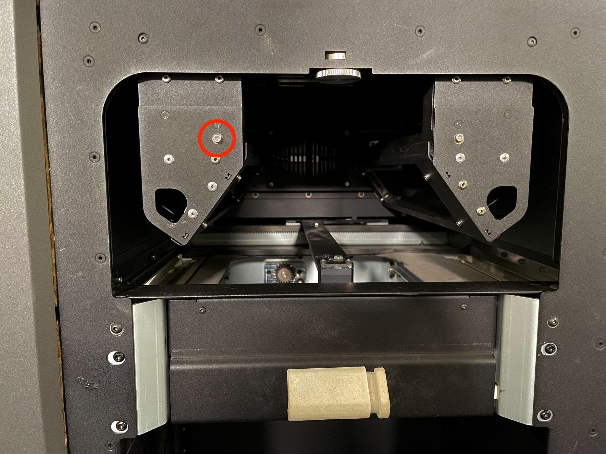
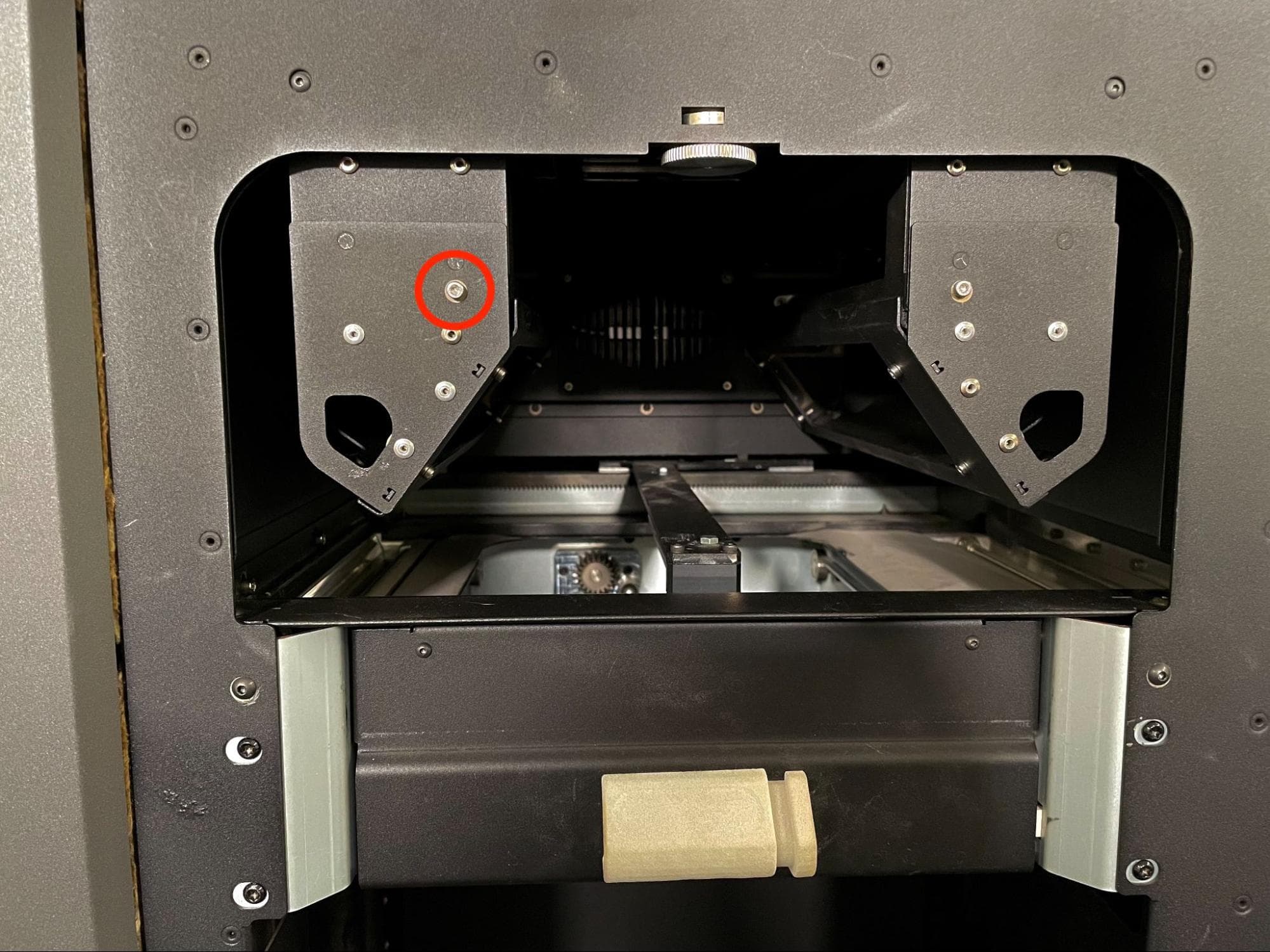
Use a 2.5 mm hex driver to remove the 8.0 mm M3 cap screw holding either quartz tube heater’s spatial filter to the frame.

Remove the heater filters

Step 4: Remove the spatial filter

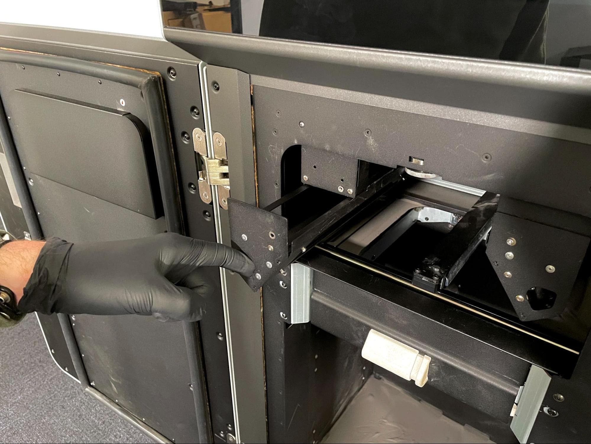
Insert your finger into the slot on the spatial filter and pull it away from the printer to remove it from the print enclosure. Set the spatial filter aside.

Remove the heater filters

Step 5: Unmount and remove the second spatial filter

Repeat steps 3–4 for the remaining filter.

Step 6: Clean the powder handling system

Follow the instructions for cleaning the powder troughs, rear powder shelf, and print enclosure from the support article Cleaning all powder out of a Fuse 1 generation printer.

Step 7: Unplug the printer

Disconnect the power cable before continuing with maintenance. Do not perform maintenance on the printer while it is connected to power. Wait five minutes after disconnecting the printer from power before proceeding.

Danger:

Performing maintenance on the printer while it is plugged in increases the risk of electric shock. Never remove the back panel of the printer while the printer is plugged in. Never reconnect the printer to power while the back panel is uninstalled.

Removing the top panel

Overview: Remove the top panel to access the interior of the printer.

Step 1: Remove the top panel screws

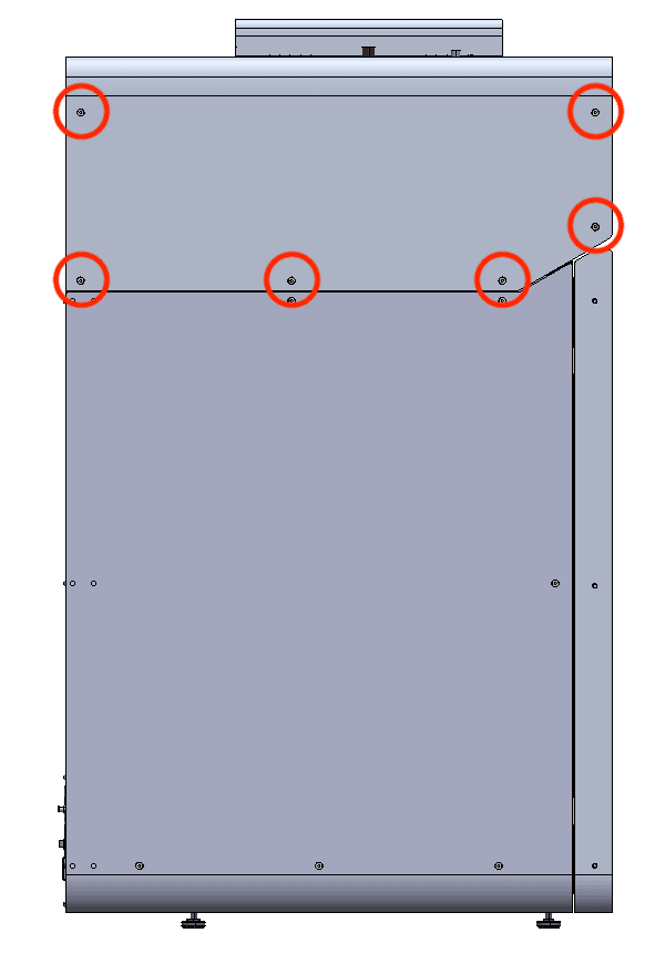
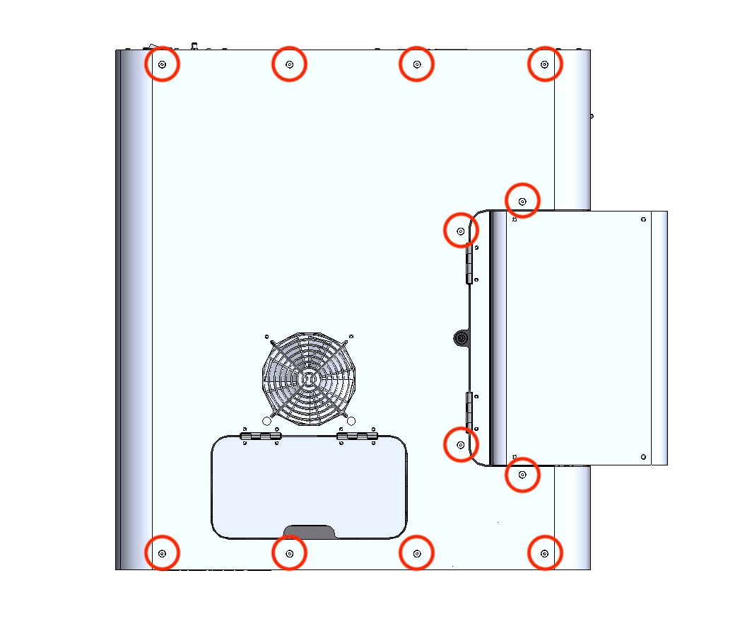
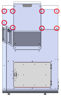
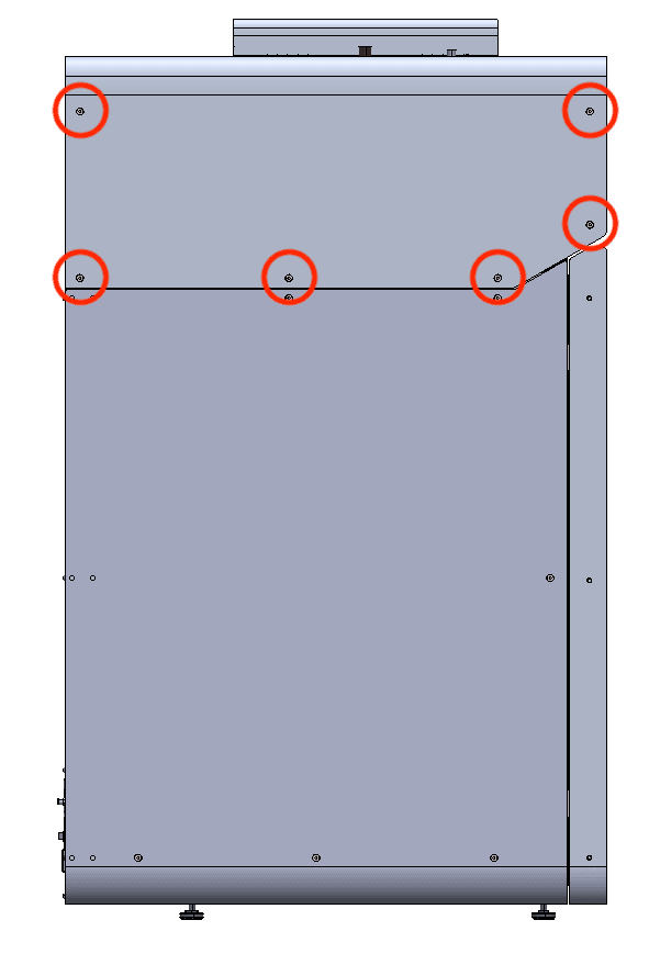
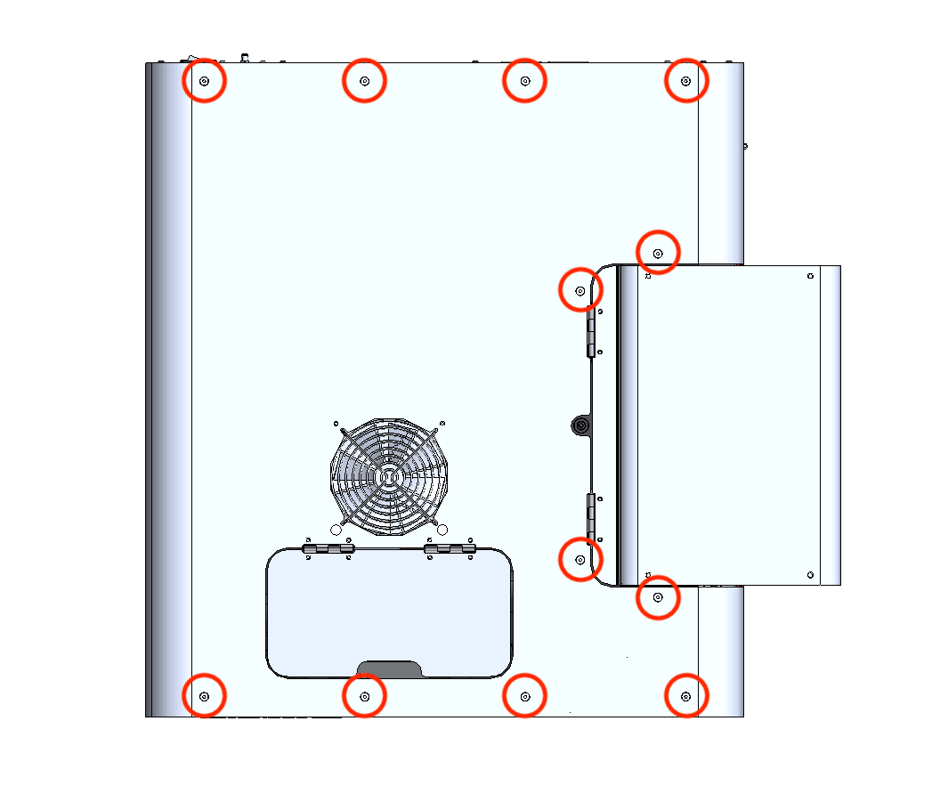
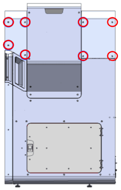
Using a 2.5 mm hex driver, remove the 26 6 mm M4 countersunk screws securing the top panel to the printer:

Remove the top enclosure panel
  • Six 6 mm screws on the front end of the buffer-side
  • 12 6 mm screws on top of the printer
  • Eight 6 mm screws on the hopper-side

Set the screws aside.

Step 2: Remove the top panel

Lift the top panel off of the printer by grabbing the IR sensor door and the rear-most edge. Set the top panel aside.

Removing the upper cooling shroud

Overview: Remove the upper cooling shroud to access the upper laser window.

Step 1: Remove the IR sensor

Removing the IR sensor

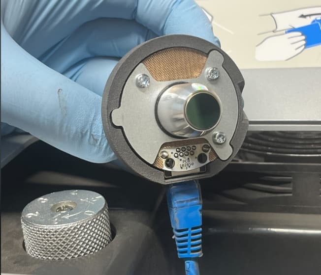
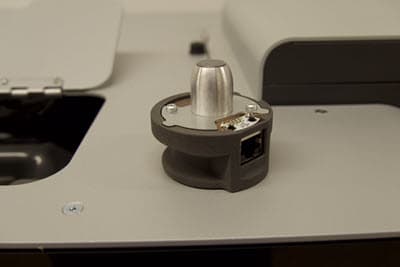
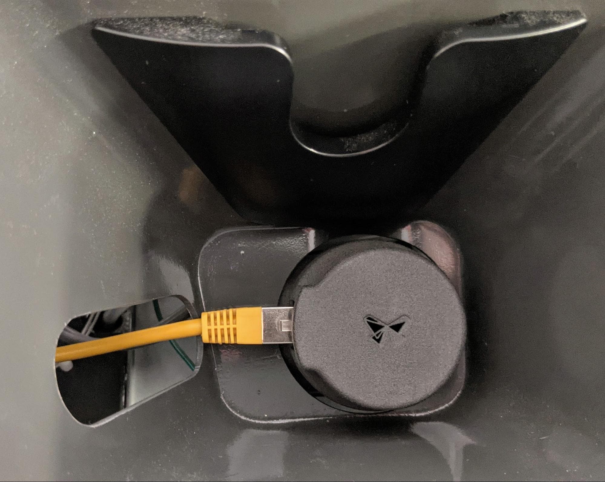
Open the access door to the IR sensor panel, located on top of the printer next to the hopper. Lift the IR sensor and disconnect the cable from it. Set the IR sensor aside on a flat surface with the sensor window facing up. Feed the IR sensor’s cable down through the plastic shroud.

Step 2: Remove the upper cooling shroud screws

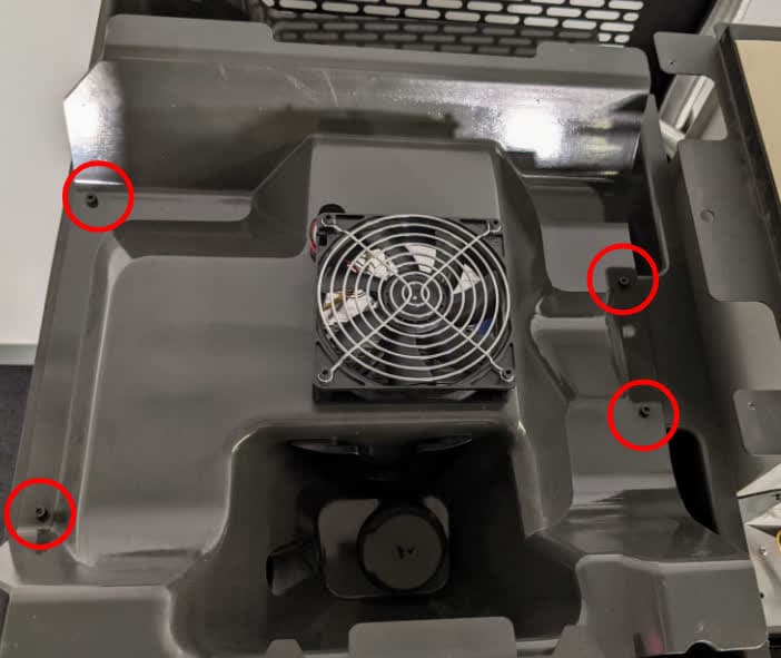
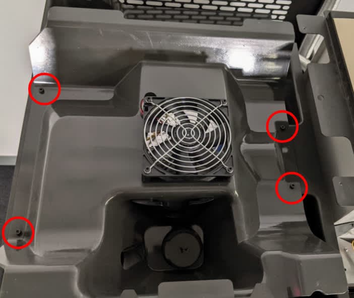
Using a 3 mm hex driver, loosen and remove the four 8 mm M4 socket head screws securing the upper cooling shroud to the printer. Do not yet separate the upper cooling shroud from the printer.

Step 3: Lift the upper cooling shroud

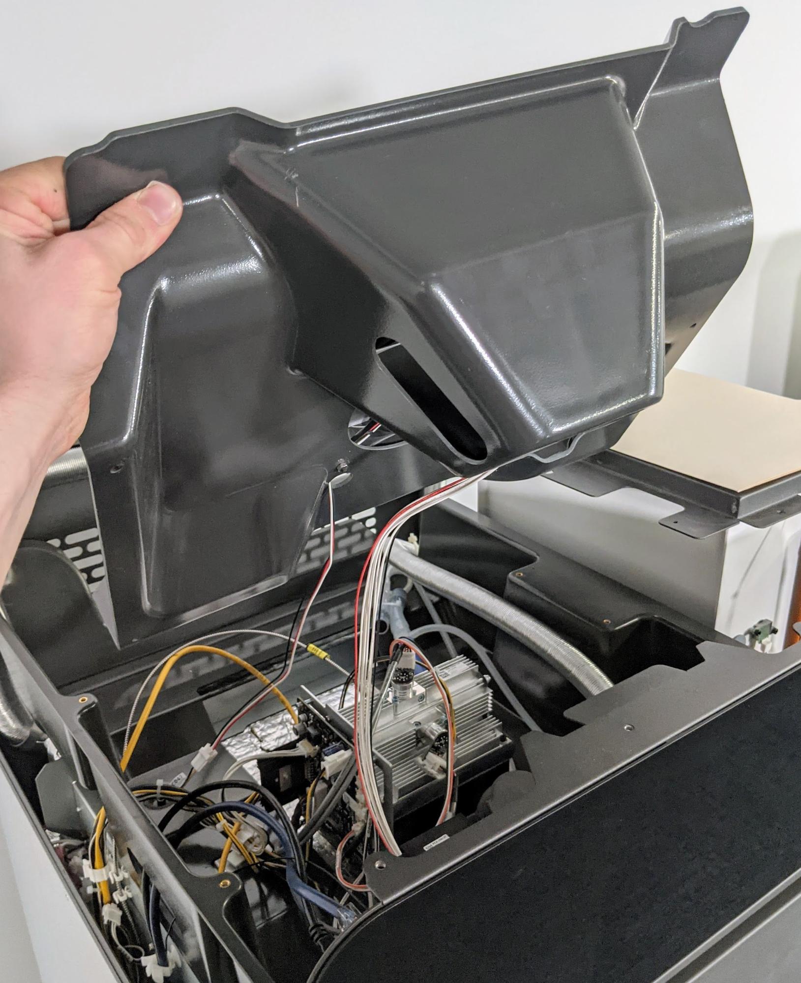
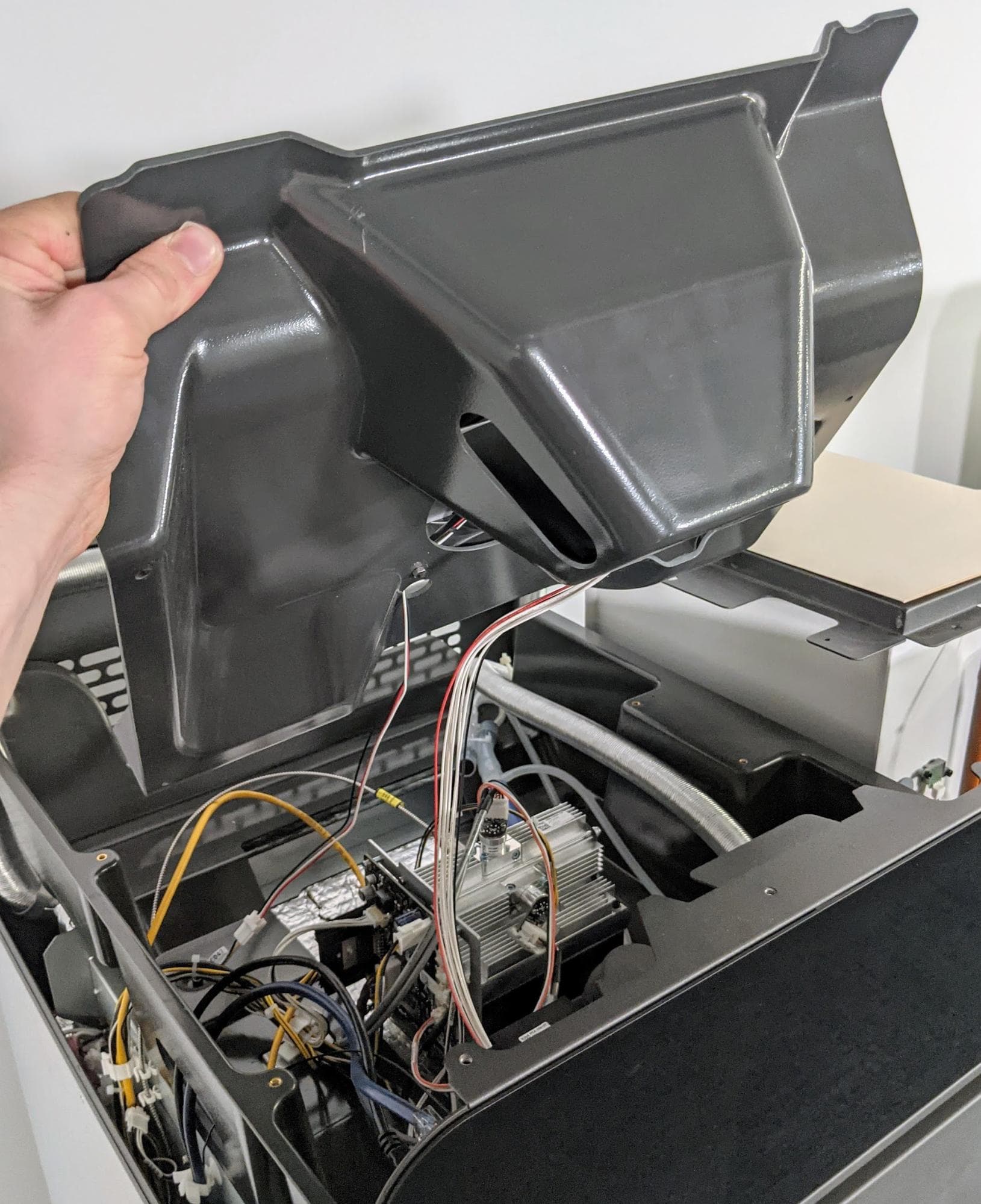
Gently lift up but do not separate the front edge of the plastic shroud from the top of the printer so that the cables attached to the shroud can be accessed.

Remove the top cooling shroud

Notice:

Take care when lifting the plastic shroud so as to not strain the cables attached to it.

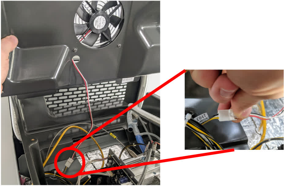
Step 4: Unplug the fan cable

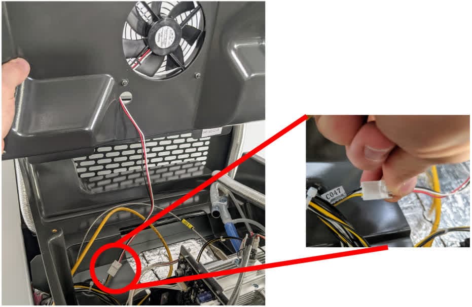
Disconnect the fan cable from the connector labeled C047 by squeezing on the plastic latch. Do not pull on the individual wires; only pull on the plastic connector.

Remove the top cooling shroud

Tip:

It may be helpful to have one person hold the plastic shroud while another person unplugs the cables.

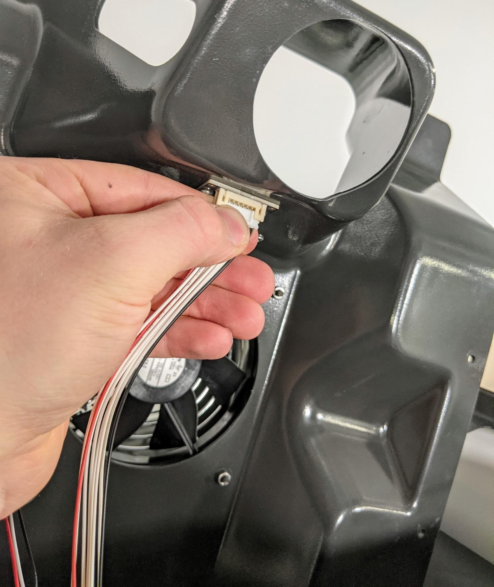
Step 5: Unplug the RFID reader (Fuse 1 only)

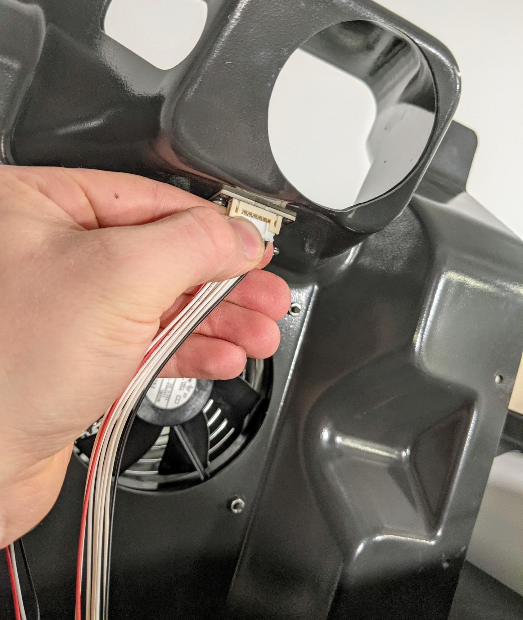
Unplug the RFID reader board cable from the circuit board by gently pulling on the white connector.

Remove the top cooling shroud

Step 6: Disconnect the nitrogen valve cable and nitrogen pressure sensor cable (Fuse 1+ 30W only)

Remove the top cooling shroud

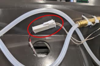
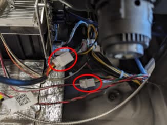
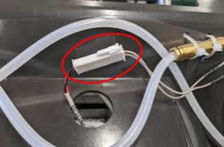
Disconnect the nitrogen solenoid valve from the cable labeled F1+ Nitro N2 Valve Cable. Disconnect the nitrogen pressure sensor from the cable labeled F1+ Nitro Pressure Sensor Cable.

For each, disconnect the cable by opening the tab and pulling the plastic connectors apart. Do not pull on the wires themselves.

Step 7: Disconnect the tubing from the upper cooling shroud (Fuse 1+ 30W only)

Remove the top cooling shroud

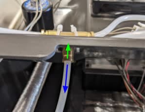
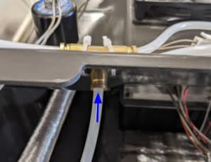
Locate the brass tee fitting on the rear side of the cooling shroud. Push the brass ring down while pulling on the plastic tube to disconnect it.

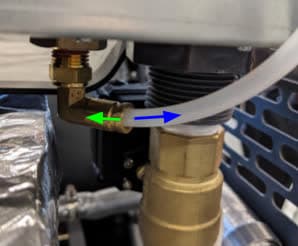
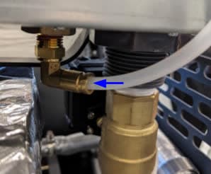
Locate the brass elbow fitting towards the rear hopper side of the printer. Push the brass ring down while pulling on the plastic tube to disconnect it.

To avoid confusing the tubes, use a permanent marker or piece of tape to label them.

Step 8: Remove the upper cooling shroud

Separate the upper cooling shroud from the printer and set it aside.

Removing the original upper laser window

Overview: Unplug and remove the original upper laser window.

Step 1: Prepare to remove the upper laser window

Put on an antistatic wrist band and connect it to a known ground point. Do not connect the wristband any surfaces that are powder-coated or painted. Put on a clean pair of nitrile gloves.

Step 2: Check the upper laser window cables

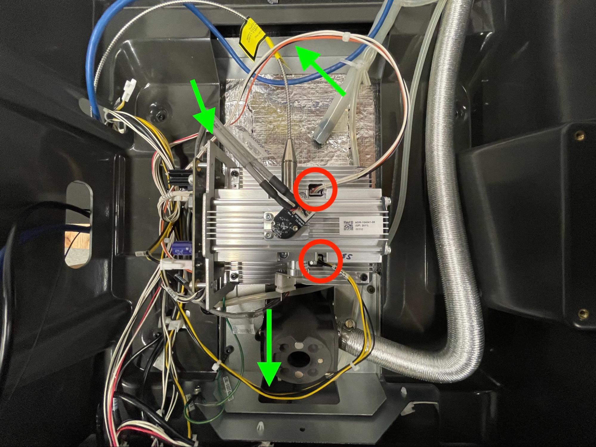
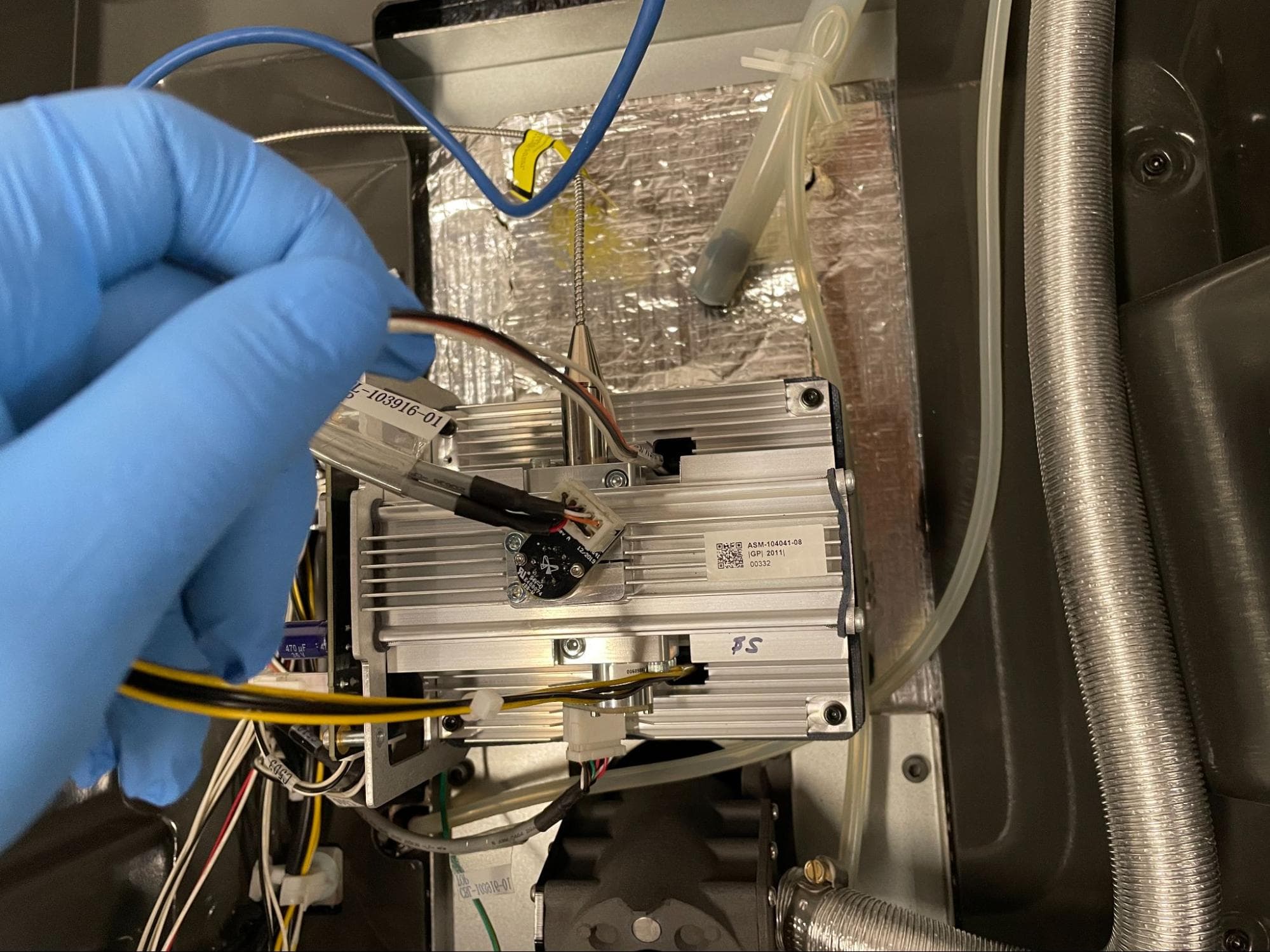
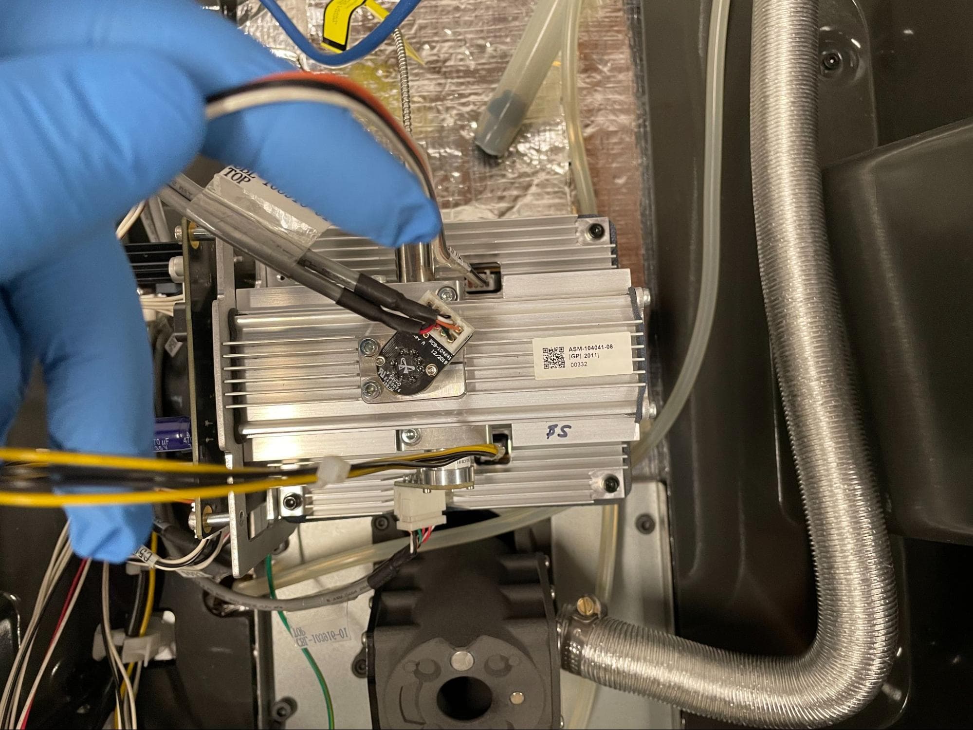
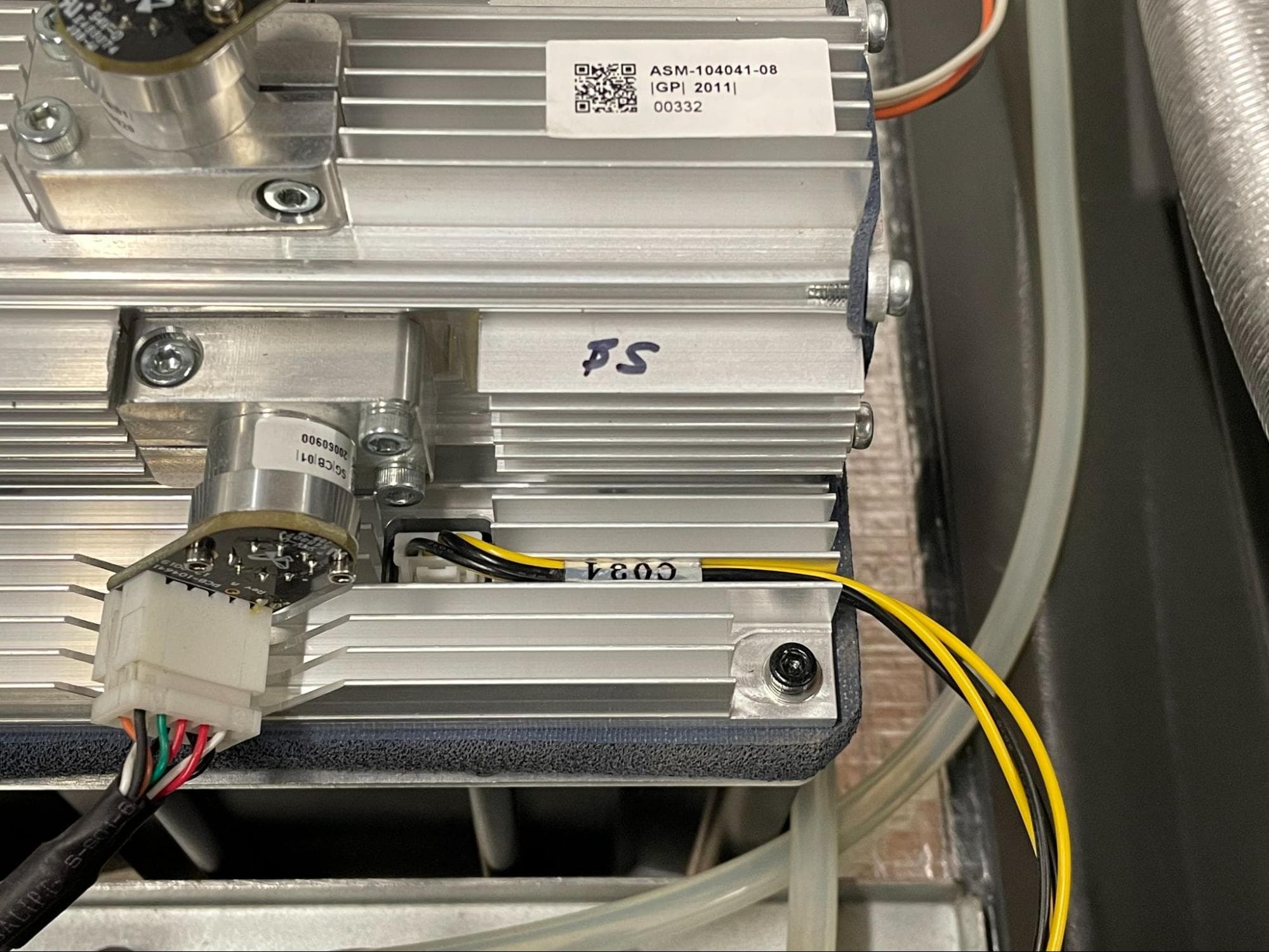
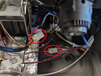
At the top of the printer, locate the two connectors nested within the galvo block labeled C049 and C034. Check that these cables are not intertwined with any other cables and are the top-most cables connected to the galvo block. If not, disconnect each one, untangle from any other cables, then reconnect them to their respective connectors. Do not cut or remove any zip ties from any cable harness in order to reroute the cables.

Leave ample slack in both cables, as they will need to follow the upper laser window as it descends into the laser shroud below.

Remove the original upper laser window

Note:

The photos in this section show a Fuse 1, but the process is the same for Fuse 1+ 30W printer.

Step 3: Open the print enclosure door

Open the filter cabinet door, then manually open the print enclosure door by pulling the blue release handle. This creates enough space to remove the display assembly.

Step 4: Remove the optical cassette

Remove the optical cassette (if one is installed) and close the cassette tray. Set the optical cassette aside.

Step 5: Loosen the upper laser window mounting screws

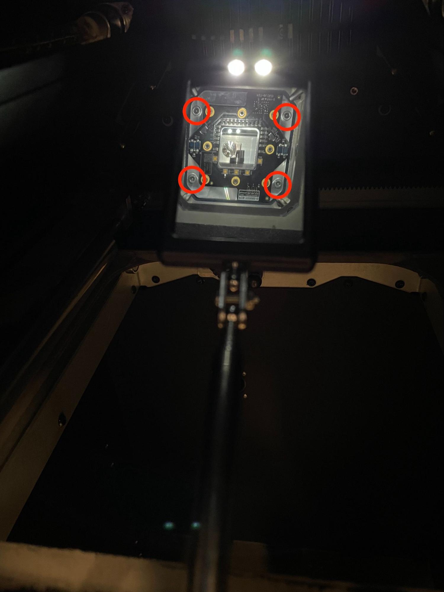
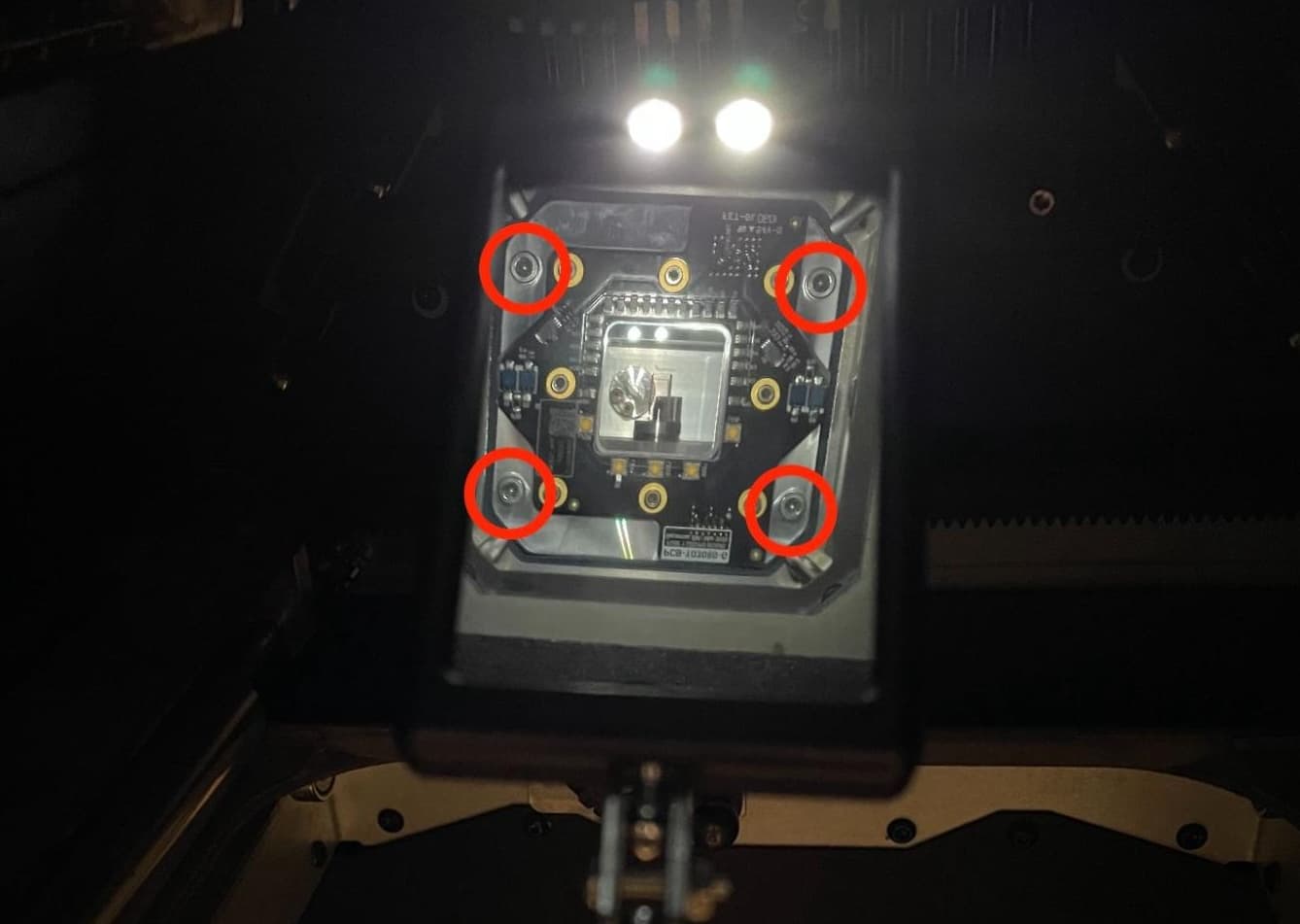
Use a telescoping backlit mirror to locate the four M4 socket head screws securing the upper laser window to the galvo block inside the laser shroud. Using a 3 mm hex driver, loosen but do not remove the four screws. Do not remove the smaller screws securing the circuit board to the upper laser window.

Remove the original upper laser window

Note:

Stop unthreading the screws once they feel loose. The screws are captive, but they could be removed if continuously driven after they are initially freed from the galvo block.

Step 6: Lower the upper laser window

If the window plate does not immediately disengage from the galvo block upon unthreading the screws, gently feed the cables labeled C049 and C034 straight down through the galvo block. This will disengage the upper laser window’s gasket from the galvo block.

Do not allow the upper laser window to suddenly fall down. Gently and evenly feed the slack of both cables into the galvo block so that the window can steadily descend.

Continue carefully feeding the cables iinto the laser shroud until the upper laser window plate reaches the base of the shroud.

Remove the original upper laser window

Step 7: Lower the upper laser window through the laser shroud

Remove the original upper laser window

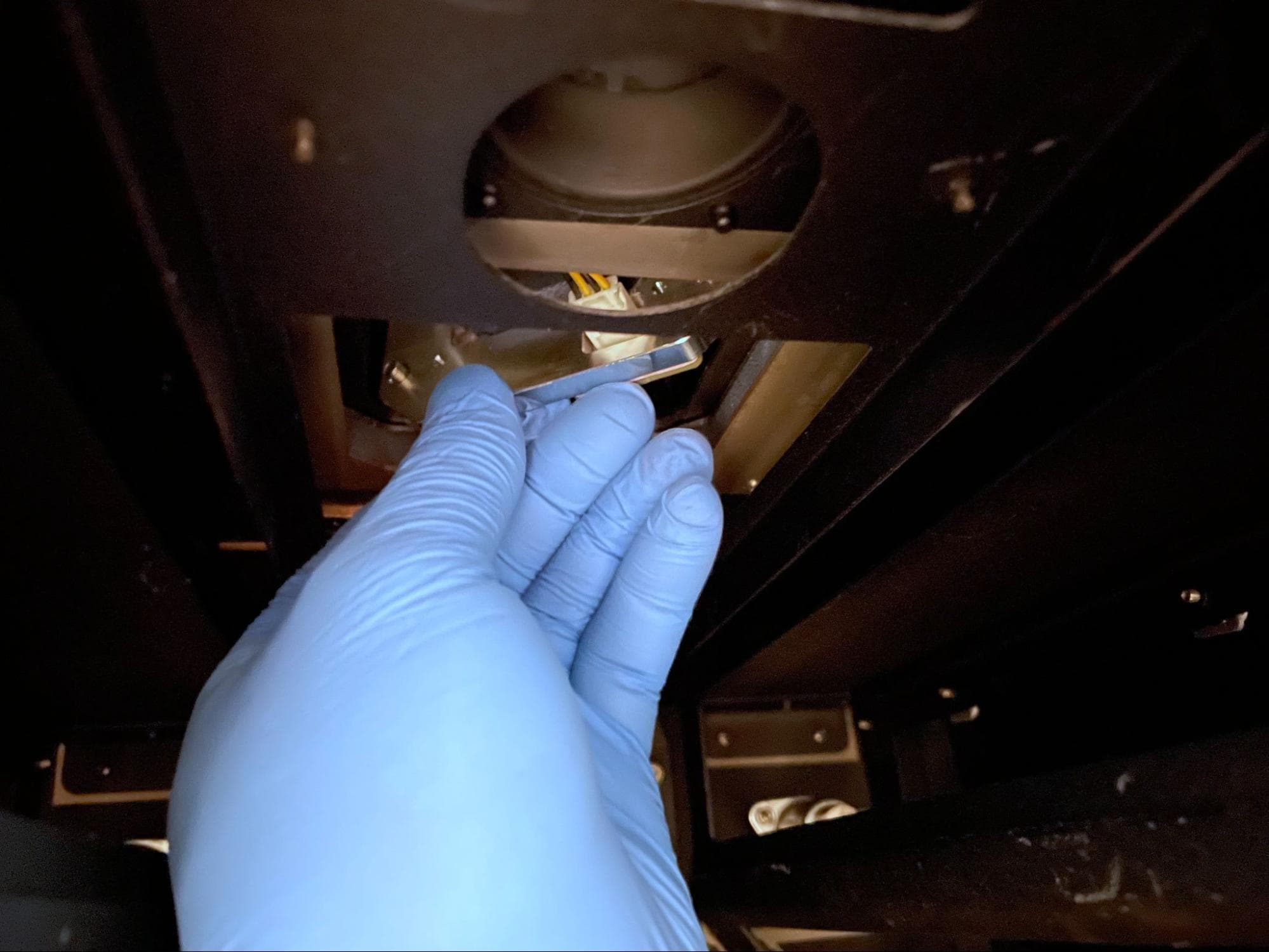
Reach into the laser shroud and gently push one side of the window plate upwards. Grab the plate with your hand, then rotate it so it can pass through the base of the laser shroud. Do not remove the upper laser window, as it is still connected to the printer via two cables.

Step 8: Disconnect the upper laser window cables

Disconnect the two cables from the upper laser window. Set the window aside for disposal with electronic waste.

Remove the original upper laser window

Installing the replacement upper laser window

Overview: Connect, mount, and secure the replacement upper laser window.

Step 1: Prepare the new upper laser window

Put on a clean pair of nitrile gloves. Prepare a flat work surface that is free of powder or any other type of debris. Remove the new upper laser window from its packaging and place it circuit board-side up onto the prepared work surface.

Step 2: Clean the lower side of the upper laser window

Install the new upper laser window

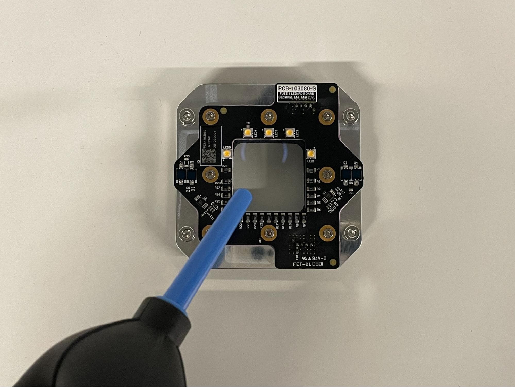
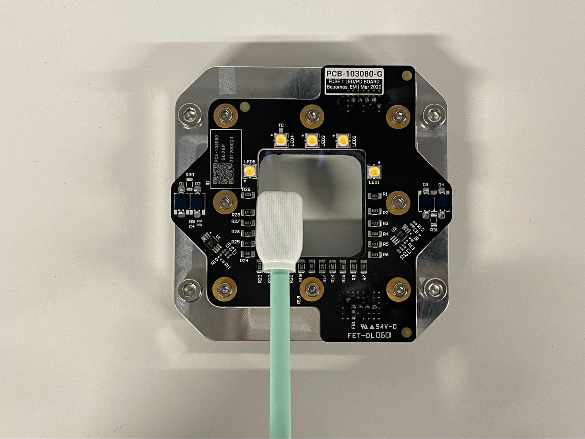
Inspect the window at various angles to ensure there are no smudges, streaks, or blemishes. It may be necessary to use a flashlight to thoroughly inspect the window if your workspace does not have sufficient overhead lighting. If the window is not clean:

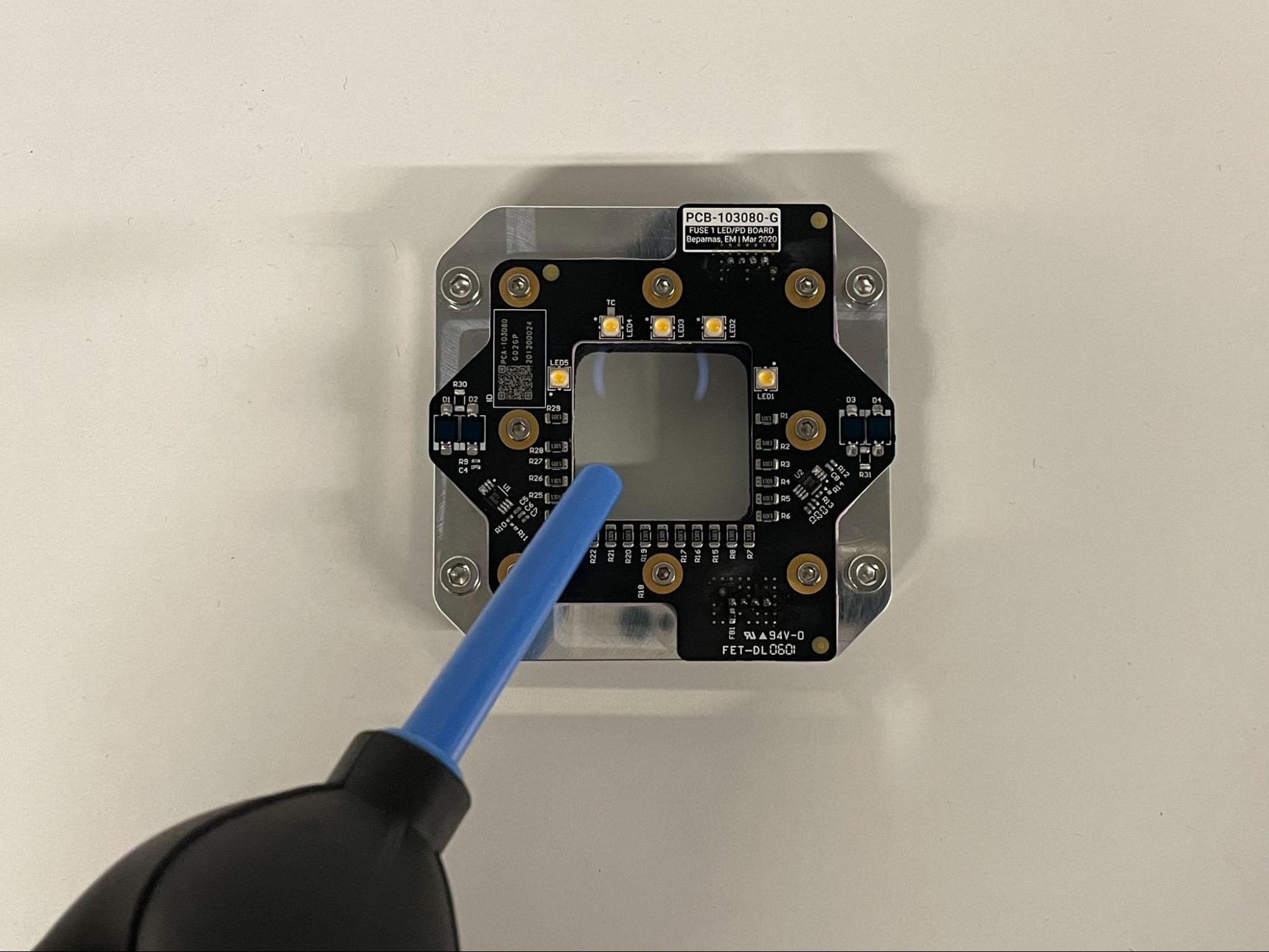
  1. Use a bulb duster to gently disperse any dust or lint off of the window.
  2. If contaminants remain after dusting, use a new, dry polyester swab to gently wipe the window in one direction with a single stroke. Repeat a perpendicular pass, if necessary.
  3. If contaminants remain after dusting and dry wiping, apply a small amount of ethanol to a new polyester swab and repeat the wiping process.

Step 3: Clean the upper side of the upper laser window

Install the new upper laser window

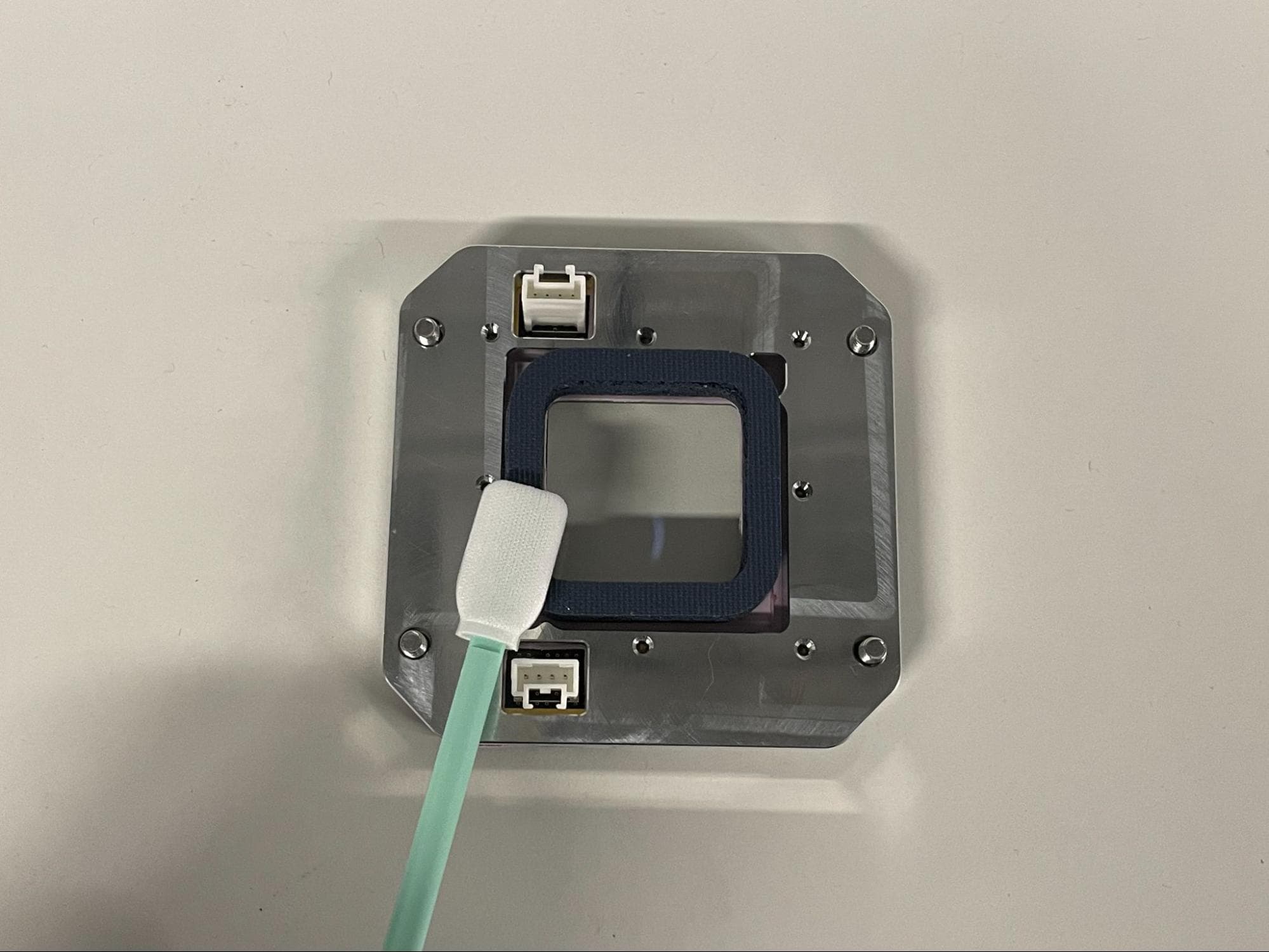
Turn the new window over to inspect the gasket on the other side. Ensure there is no debris or residue of any kind on the top face of the gasket. If the gasket is not clean, apply a small amount of ethanol to a new polyester swab and gently wipe the gasket in a single direction.

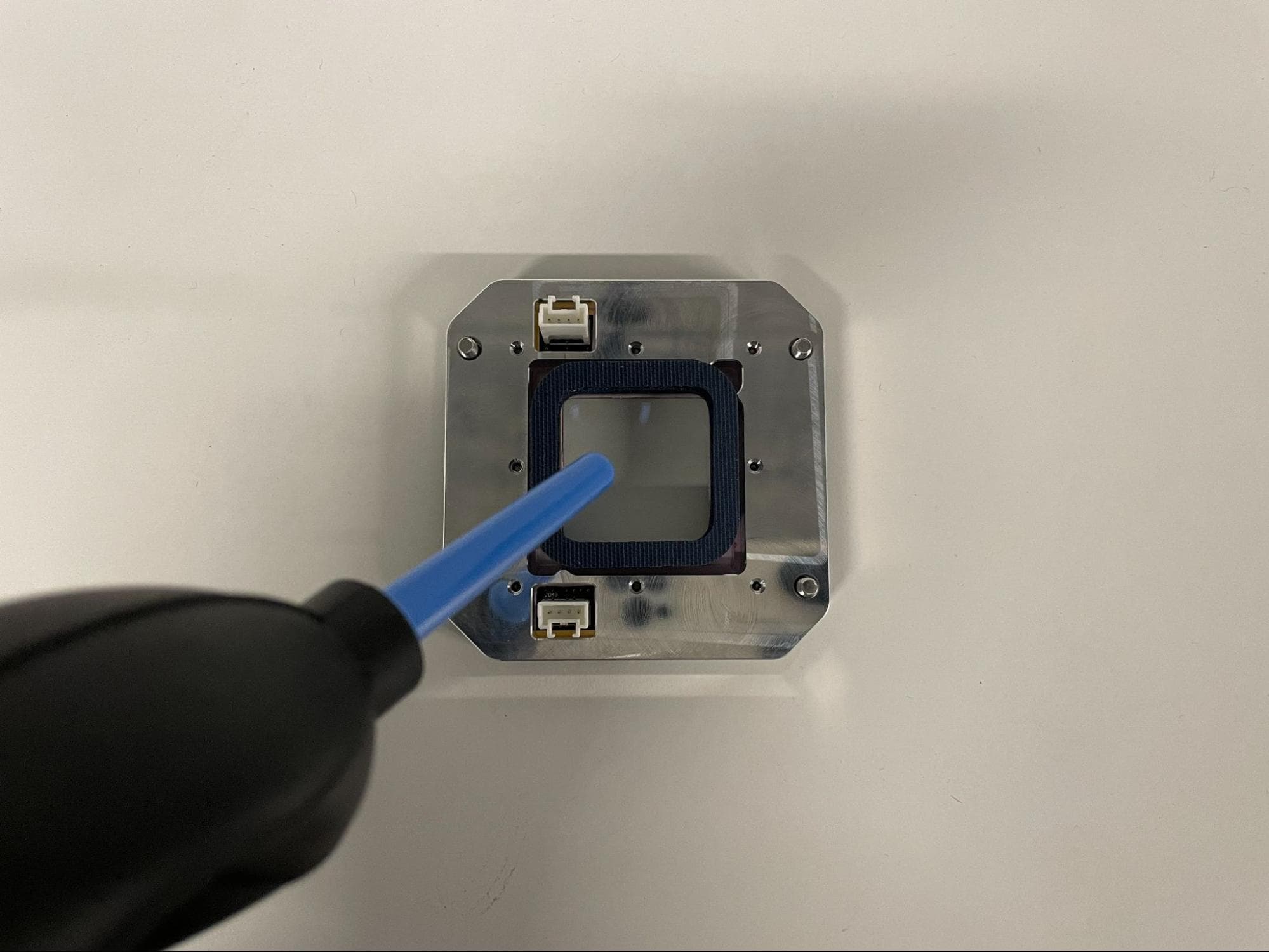
Use a bulb duster to disperse any dust or lint that may be present on the window or frame.

Step 4: Connect the upper laser window cables

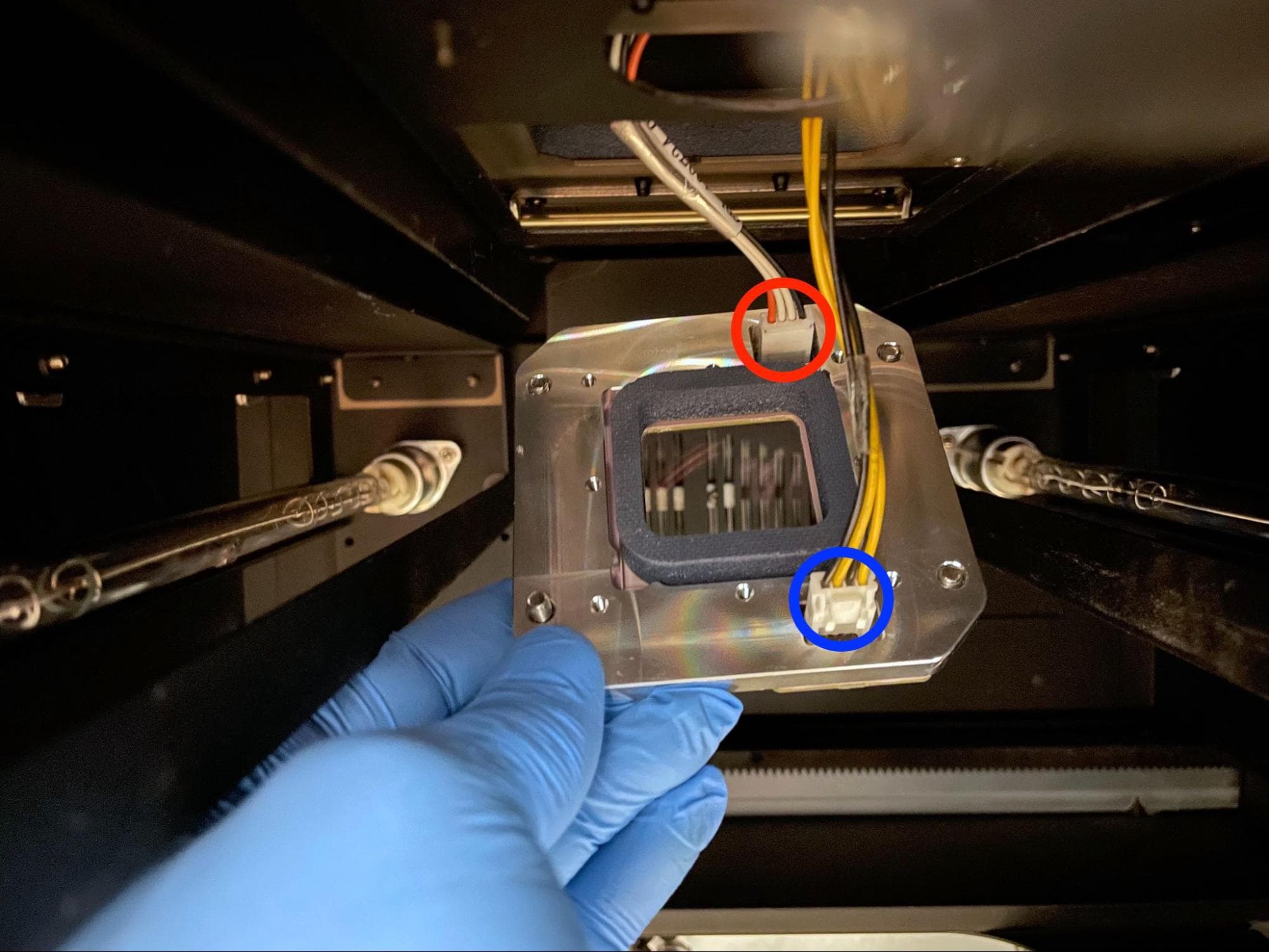
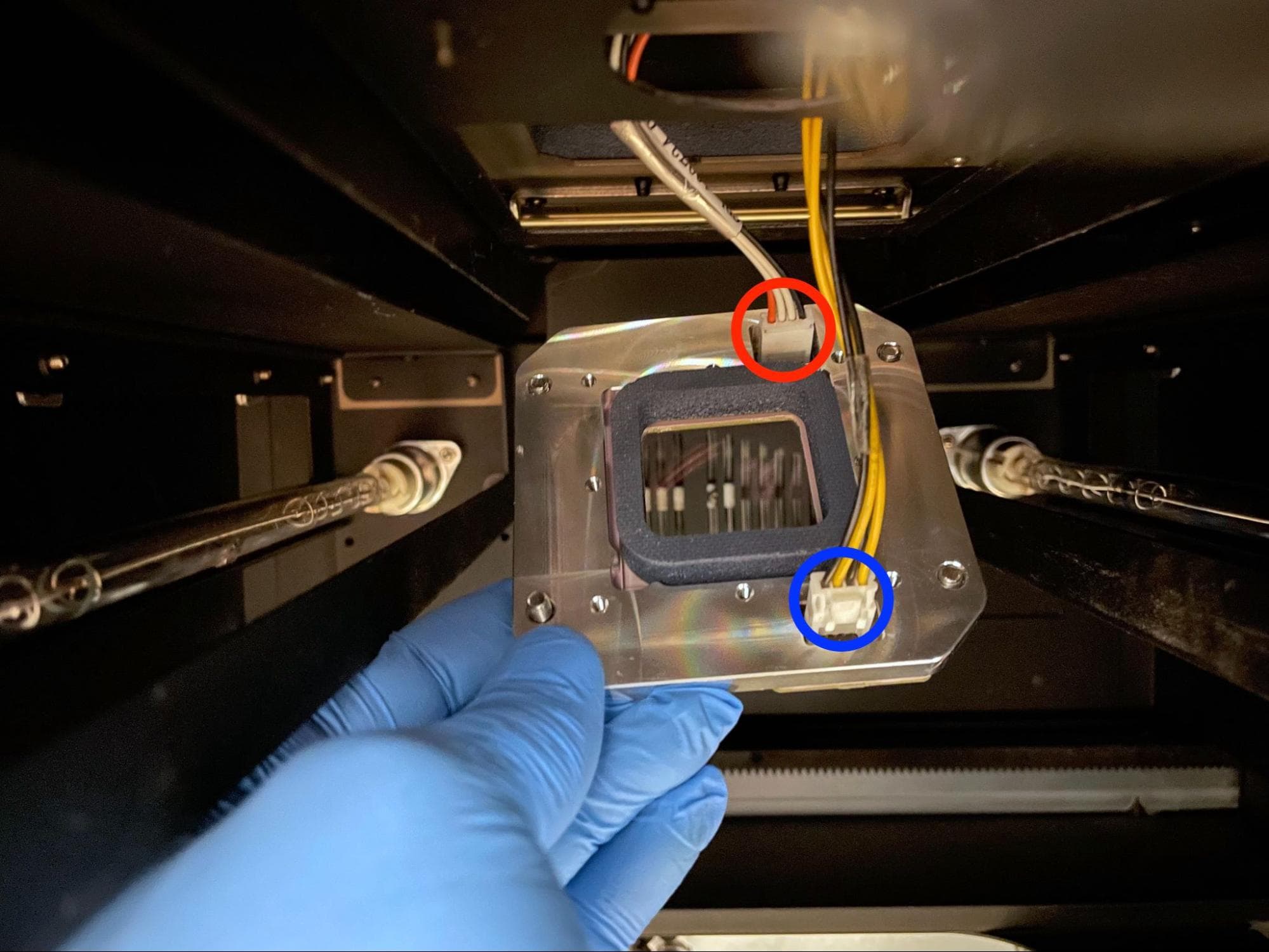
Handle the new window by gripping the aluminum plate. Avoid touching the glass, even with gloves, to prevent introducing any contaminants to the sealed space behind the window. Position the window so that the gasket is facing up and the connectors are on the right-hand (or hopper side) of the printer.

Ensure that the upper laser window cables are not tangled, then connect them to the upper laser window. Connect cable C049 to the rear connector and cable C034 to the front connector.

Install the new upper laser window

Step 5: Lift the upper laser window into the laser shroud

Install the new upper laser window

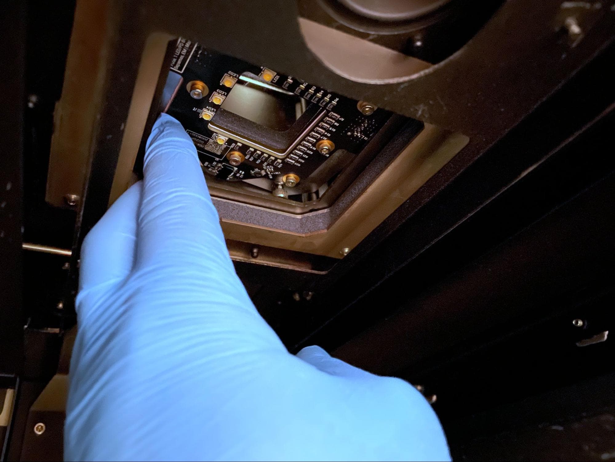
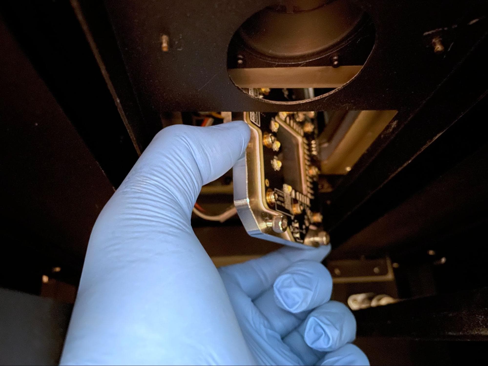
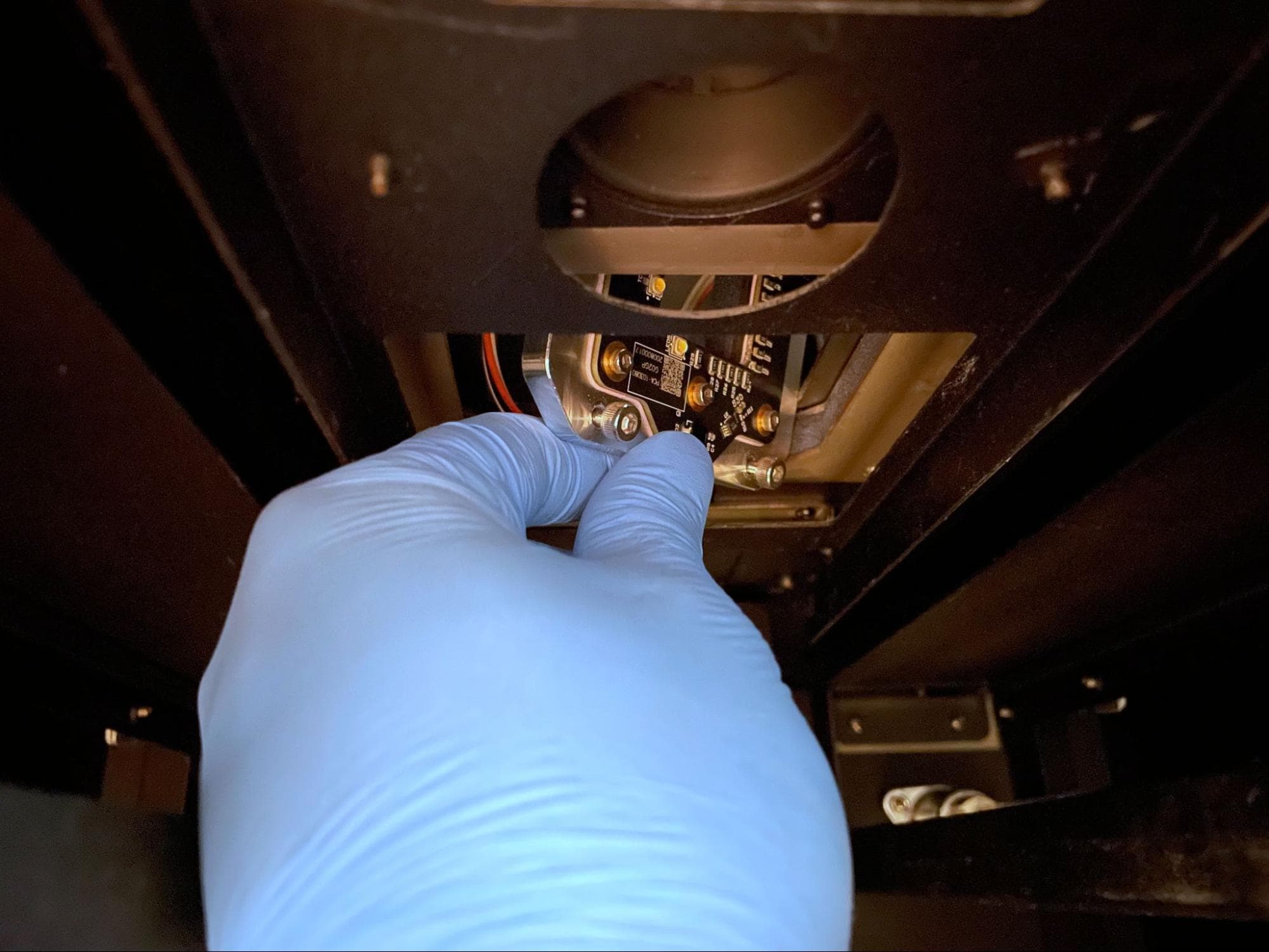
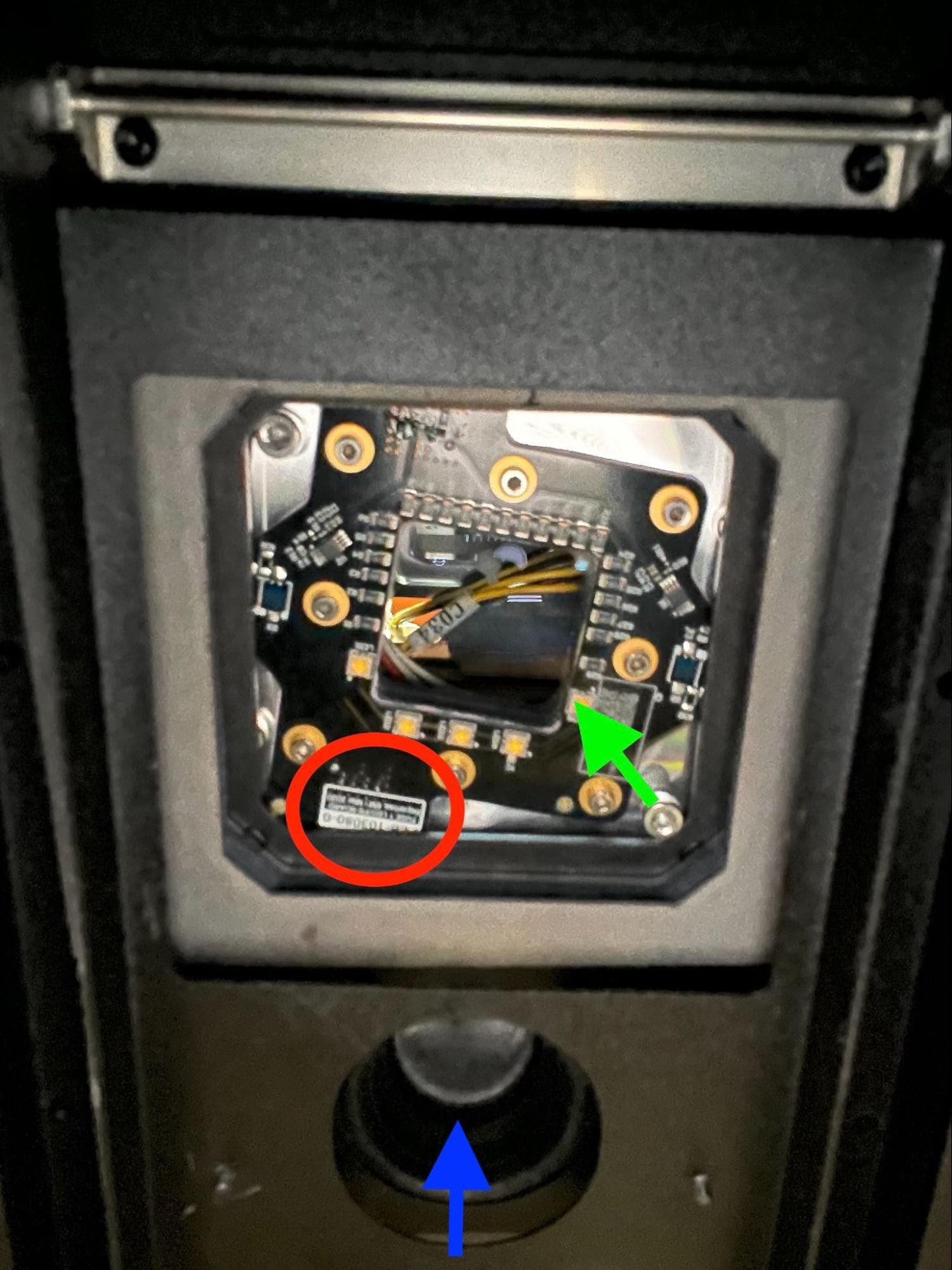
Turn the upper laser window plate so the connectors are behind the window and the circuit board is at a 45º angle to the door handle. Carefully maneuver the new window plate into the shroud, then reposition it so the circuit board is facing downward into the print enclosure. Ensure the circuit board’s label is oriented to be between the IR sensor aperture and the upper laser window. If not, remove the window and re-insert it into the laser shroud.

Let the window plate rest on the base of the laser shroud.

Step 6: Lift the upper laser window towards the galvo block

From above, gently hoist the window upward by slowly pulling in the slack in both cables simultaneously. The small zip ties on the cables may catch the lip just below each cable’s passthrough hole. Do not pull, yank, or tug on either cable if the window feels stuck or wedged. Instead, slowly release the slack in both cables until the window is freed, then try again.

Install the new upper laser window

Step 7: Route the upper laser window cables

Install the new upper laser window

Reach up into the laser shroud and gently push the window plate up towards the galvo block. Avoid pushing directly on the window.

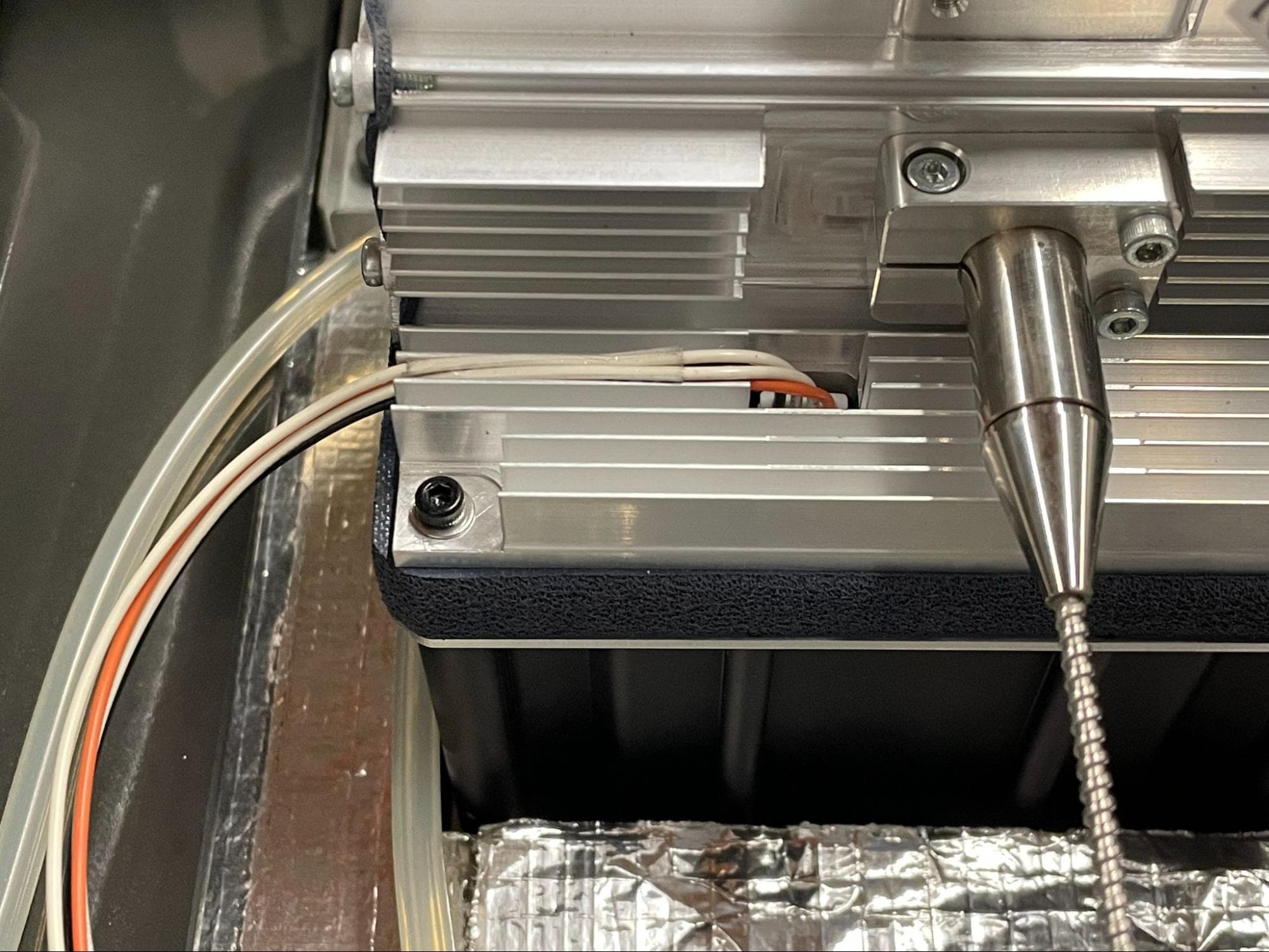
While still pushing up on the window plate, gently feed the upper laser window cables into an adjacent fin of the galvo block. Feed the label portion into a fin first, followed by the remaining individual wires. Forcing the individual wires into the fins first may gouge or tear the insulation.

Step 8: Mount the upper laser window

Thread one M4 socket head screw into each of the four holes in the upper laser window. You may need to push each screw upward in order to engage the threads due to the force exerted onto the window plate by the window’s gasket. Do not tighten the screws at this time.

Install the new upper laser window

Step 9: Secure the upper laser window

Once all four screws are loosely threaded into the galvo block, hand-tighten each one in the order shown here until snug. After an initial torquing pass, check each screw at least twice in the exact order they were torqued. Always check all four screws even if just one is still loose.

Install the new upper laser window

Step 10: Reroute the upper laser window cables

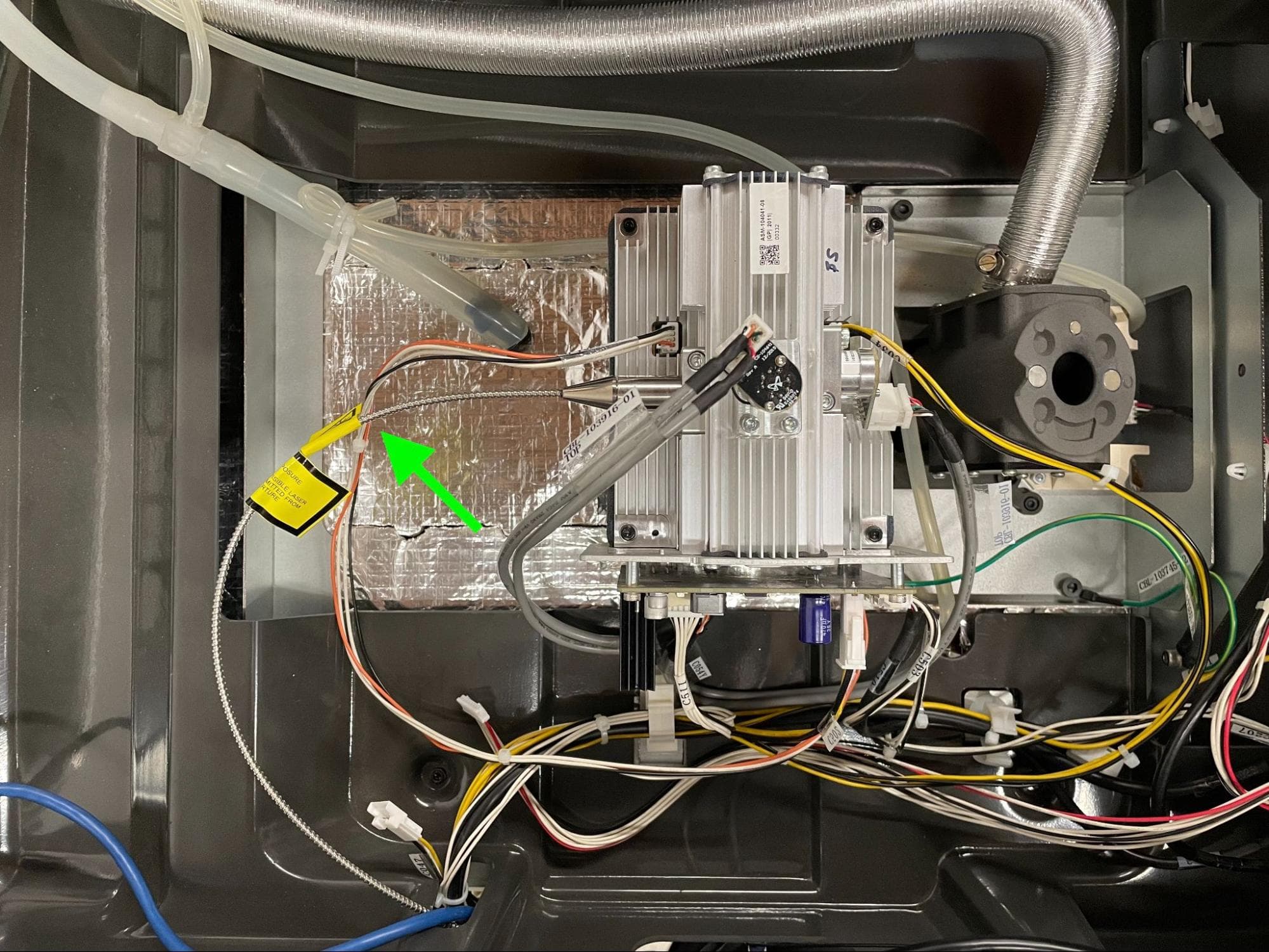
Separate the upper laser window cables from the galvo block heatsink fins, then reroute cable C049 so that it passes under the laser fiber.

Install the new upper laser window

Step 11: Reinstall the optical cassette.

Reinstall the optical cassette into the cassette tray. Close the cassette tray.

Reinstalling the upper cooling shroud

Overview: After replacing the upper laser window, reinstall the upper cooling shroud.

Step 1: Reonnect the RFID reader cable (Fuse 1 only)

Hold the upper cooling shroud above the printer and plug the RFID reader cable connector into the RFID board by gently pushing it into the receptacle. The connector will only fit in one orientation.

Replace the top cooling shroud

Step 2: Reconnect the cooling fan

Reconnect the cooling fan connector to the socket labeled C047.

Replace the top cooling shroud

Step 3: Reconnect the nitrogen valve cable and nitrogen pressure sensor cable (Fuse 1+ 30W only)

Replace the top cooling shroud

Reconnect the solenoid valve to the cable labeled F1+ Nitro N2 Valve Cable. Reconnect the N2 pressure sensor to the cable labeled F1+ Nitro Pressure Sensor Cable.

Step 4: Route the IR sensor cable

Position the top cooling shroud by holding it from the front edge so that the cables covered by the shroud can still be accessed. Feed the IR sensor’s Ethernet cable back through the cutout in the top shroud.

Replace the top cooling shroud

Step 5: Mount and secure the upper cooling shroud

Lower the upper cooling shroud on the printer, aligning the four screw holes in the shroud with the corresponding screw holes in the printer frame. Thread one 8 mm M4 socket head screw into each of the screw holes. Using a 3 mm hex driver, tighten until snug.

Replace the top cooling shroud

Step 6: Route the nitrogen solenoid valve tubing (Fuse 1+ 30W only)

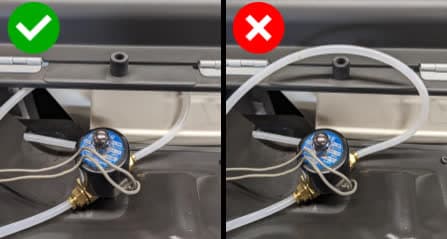
Tuck the plastic tube connected to the nitrogen solenoid valve under the sheet metal hopper cover as shown.

Replace the top cooling shroud

Step 7: Reconnect the tubing to the upper cooling shroud (Fuse 1+ 30W only)

Replace the top cooling shroud

Locate the brass tee fitting on the rear side of the cooling shroud. Push the plastic tube firmly into the fitting.

Locate the brass elbow fitting towards the rear hopper side of the printer. Push the plastic tube firmly into the fitting.

After insertion, pull on the tubes gently to ensure they do not come out.

Step 8: Connect and mount the IR sensor

Inspect the IR sensor lens for debris and clean it if necessary. Attach the ethernet cable to the IR sensor, then place the sensor back into its mount.

Replace the top cooling shroud

Reinstalling the top panel

Overview: After replacing the upper laser window, reinstall and secure the top panel.

Step 1: Align the top panel

Lift the top panel and place it on top of the printer. Align the screw holes in the top panel with the corresponding holes in the printer frame.

Step 2: Secure the top panel screws

Thread a 6 mm M4 countersunk screw into each of the 18 marked screw holes in the top panel:

Remove the top enclosure panel
  • Six 6 mm screws on the front end of the buffer-side
  • 12 6 mm screws on top of the printer
  • Eight 6 mm screws on the hopper-side

Using a 2.5 mm hex driver, tighten the screws until snug.

Reinstalling the quartz tube heater spatial filters

Overview: Align and reinstall the spatial filters.

Step 1: Align the spatial filter with the frame

Align the slots on the spatial filter with the rails on the lamp frame.

Step 2: Install the spatial filter

Replace the heater filters

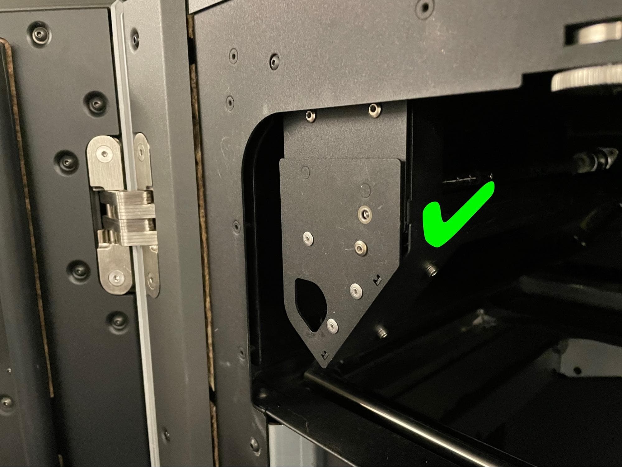
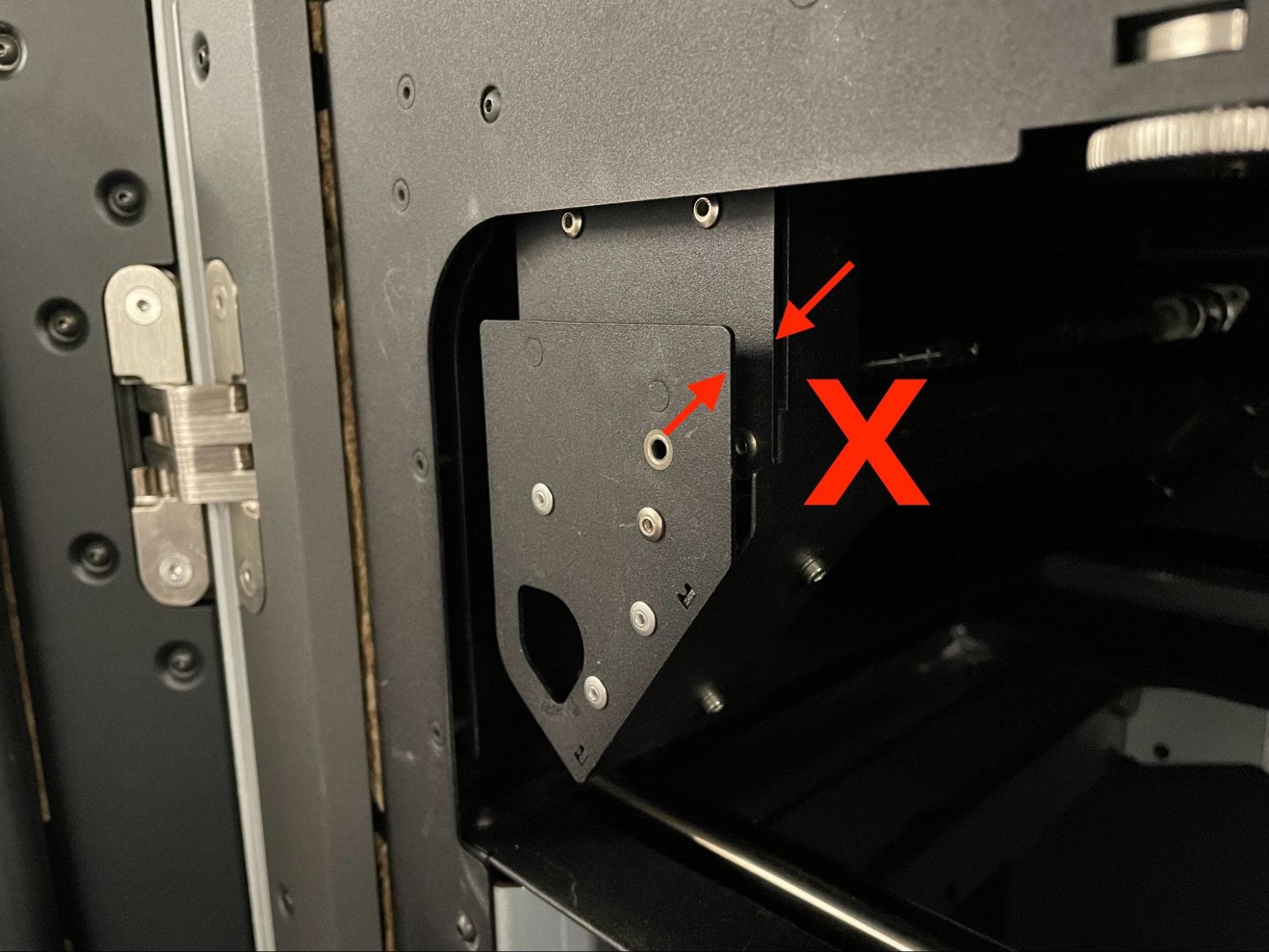
Push the spatial filter along the rails towards the back of the printer. Ensure that the alignment pins on the back of the front face of the spatial filter go into the corresponding holes in the lamp frame. The front of the spatial filter sits flush against the front of the lamp frame when it is properly installed.

Step 3: Secure the spatial filter

Thread the 8.0 mm M3 cap screw into the screw hole in the front of the spatial filter. Tighten the screw with a 2.5 mm hex driver until finger tight.

Replace the heater filters

Step 4: Install and secure the other spatial filter

Repeat steps 1–3 for the other filter.

Finalizing the repair

Overview: After installing the replacement upper laser window, power on the printer and perform final checks.

Step 1: Power on the printer

Connect the power cable to the printer and the power supply. The printer initializes.

Step 2: Test the repair

Start a print. Monitor the printer to ensure that the print proceeds normally. Contact Formlabs Support or your certified service provider to share the results of the procedure.