
Note:
Formlabs has sunsetted this material, and it is no longer available for purchase. For information about other Formlabs materials, visit Choosing the right material.

Note:
Formlabs has sunsetted this material, and it is no longer available for purchase. For information about other Formlabs materials, visit Choosing the right material.
Read and follow the Ceramic Resin V1 Usage and Design Guide to print successfully with Ceramic Resin V1.
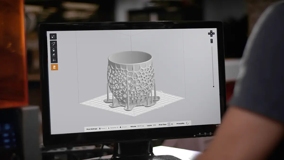
Note:
To learn more about the performance or specific material properties of Ceramic Resin V1, please refer to the Safety Data Sheet (SDS) and Technical Data Sheet (TDS). Always consult the SDS as the primary source of information to understand safety and handling of Formlabs materials.
Tip:
Parts often require several scaling iterations to reach the desired fired dimensions.
Part volume
Maximum: 100 mL
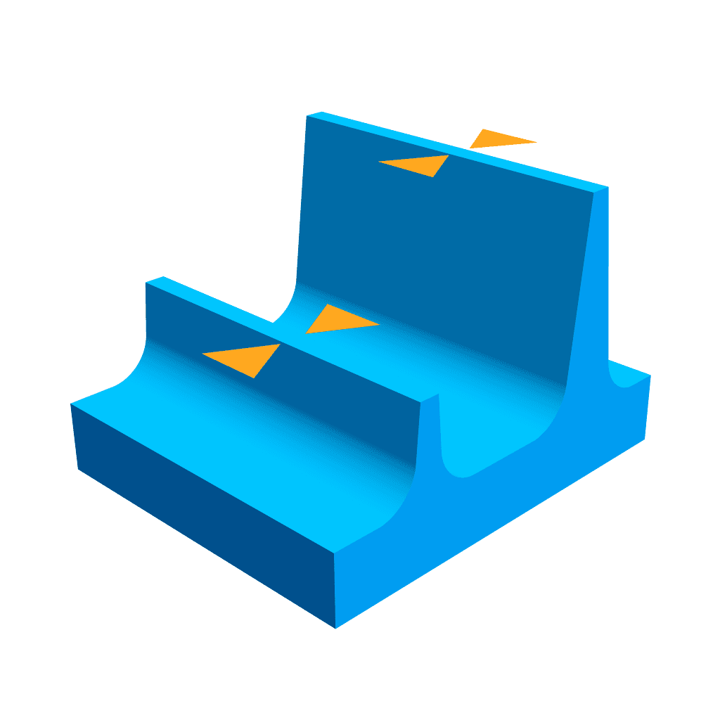
Fired wall thickness
Minimum: 2 mm
Ideal: 3–6 mm
Maximum: 10 mm
Small walls and features may work under 2 mm
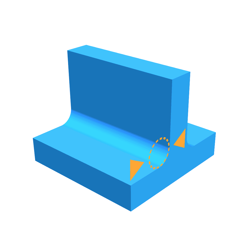
Filleting
Fillet internal edges to avoid stress concentrations and decrease cracking:
Minimum: 1 mm fillet radius
Ideal: 2 mm or more
Z-shrinkage
During firing, parts shrink more along the printed Z axis than the XY axis due to the lower concentration of ceramic particles between layers. If a model is printed at an angle, this causes a skewing effect when fired. To correct the effect of uneven shrinking, pre-scale the model using the Z-Scale Factor tool in PreForm. The part shape will correct during firing.
General shrinkage
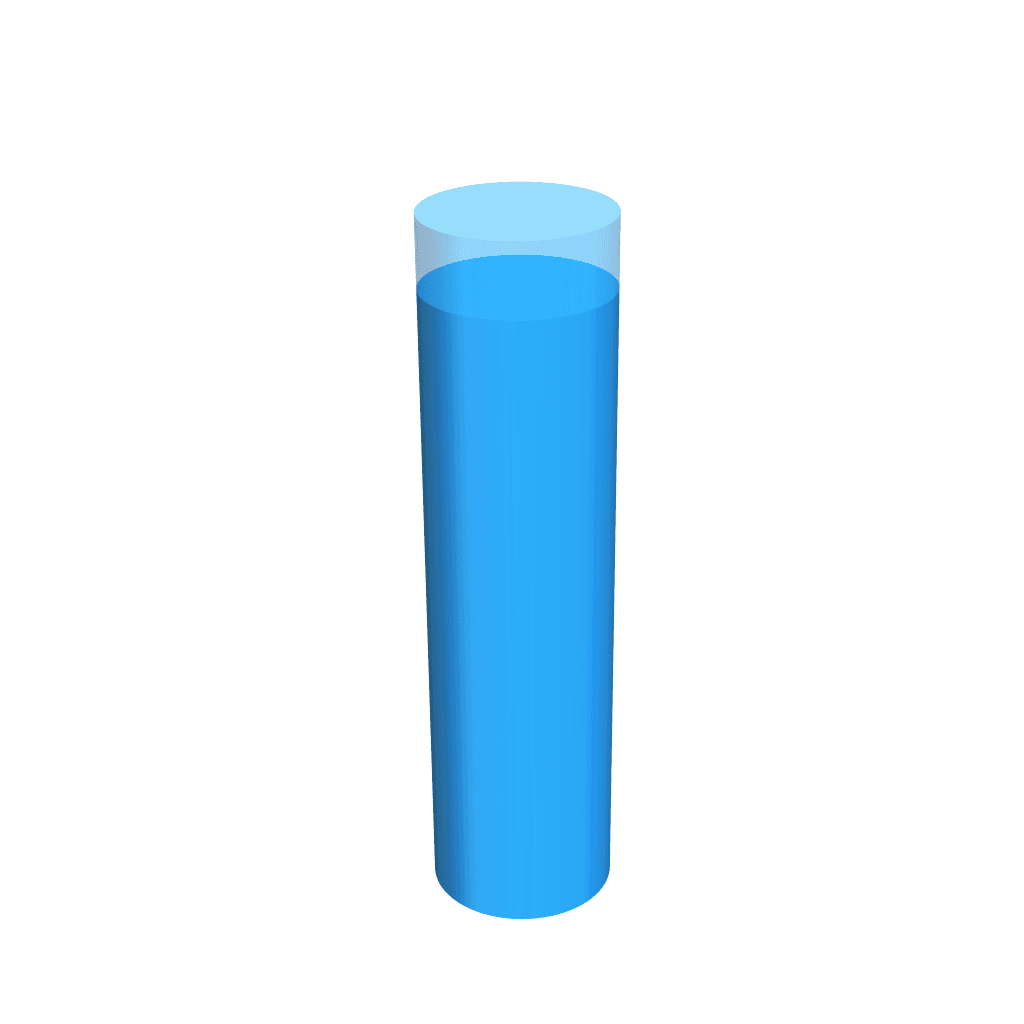
Shrinkage is caused by sintering and gives Ceramic Resin V1 its strength by increasing the density of the part. General shrinkage occurs uniformly across the part, and parts shrink by approximately 15% during sintering. After setting the Z-Scale Factor use the Size tool in PreForm to set the Scale to 1.15 to account for shrinkage.
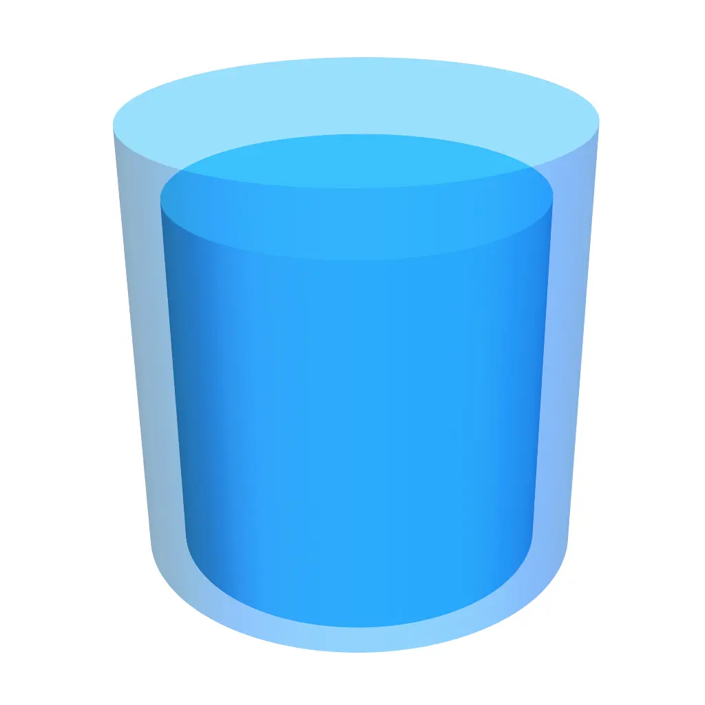
Self-supporting structures
Ceramic particles can move during sintering, which means the shape of the model is affected by gravity. Self-supporting structures maintain their shape, but unsupported overhangs tend to slump or collapse. Design structures that are self-supporting to minimize the volume of support structures and to prevent slumping during firing.
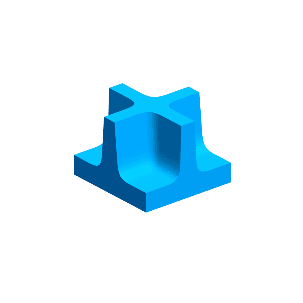
Unsupported structures
Unsupported structures, such as overhangs and bridges, are often unavoidable. There are two major ways to control the potential slumping effect: Print custom setters. Setters should be designed and oriented to shrink in the same direction as the part. Fire on supports.

Additional resources