WHITE PAPER
Formlabs Logo

Replacing the Form 3L cartridge floor

Replacing the Form 3L cartridge floor

When inserted into the printer, resin cartridges sit on the cartridge floor, which contains sensors for detecting and identifying the cartridge and an actuator for dispensing resin. The Form 3L contains two cartridge floors, one for each resin cartridge that can be inserted. If one of the cartridge floors is malfunctioning or broken, the printer may fail to detect one of the resin cartridges or not dispense resin properly.

Use this guide to remove and replace the Form 3L cartridge floor.

f3l-cartridge-floor-standalone.jpg

Required Supplies:

Formlabs:

  • Replacement cartridge floor
  • Flush cutters (included with Form 3L Finish Kit)
  • Formlabs resin cartridge

Third-party:

  • T8 Torx driver
  • T10 Torx driver
  • 2.5 mm hex driver
  • M3 (5.5 mm) socket wrench
  • Cable ties
  • Nitrile gloves
  • Polyimide tape
  • Permanent marker (optional)
  • Cyanoacrylate glue (optional)
  • Precision tweezers (optional)
Estimated time: 45–60 minutes

DANGER:

Read and follow all safety instructions and warnings in the operator manual. Replacement with incorrect parts can lead to burns, shock, fire, or explosion. Dispose of all parts in accordance with local regulations.

Preparing the workspace

Overview: Prepare the Form 3L and a dust-free workspace for replacing the cartridge floor.

Step 1: Remove the build platform

Remove the build platform first to avoid dripping resin onto the LPU or into the printer cavity.

Step 2: Remove the resin cartridges

Remove the resin cartridges and close the vent caps to prevent resin from dripping off of the bite valves and into the printer.

Step 3: Remove and store the resin tank

Remove the resin tank, place it in the resin tank case, and cover it with its lid. Set the case and tank aside on a clean, flat surface.

NOTICE:

Wear gloves and hold the resin tank by the tank grips on either side to avoid contamination or damage to the underside of the tank.

Step 4: Prepare the workspace

Clear a workspace around your printer. Ensure that the workspace is well-ventilated and free of dust. Prepare additional space for storing the rear panel of the printer during maintenance.

Step 5: Clean the printer cavity

WARNING:

Resin may cause skin irritation or an allergic skin reaction. Wear gloves when handling liquid resin or resin-coated surfaces. Wash skin with plenty of soap and water.

Open the printer cover. Clean any resin pooled on the printer floor, inside the printer cavity, with paper towels. Dampen the paper towels with isopropyl alcohol if necessary to fully remove the resin.

DANGER:

Fire hazard. IPA is flammable. Keep containers closed, and keep out of the reach of children.

Step 6: Unplug the networking cables and Wi-Fi antenna

Disconnect the Ethernet and USB cables from the printer, if they are connected. Unscrew and remove the Wi-Fi antenna.

Step 7: Unplug the printer

Disconnect the power cable before continuing with maintenance. Do not perform maintenance on the printer while it is connected to power. Wait five minutes after disconnecting the printer from power before proceeding.

DANGER:

Performing maintenance on the printer while it is plugged in increases the risk of electric shock. Never remove the back panel of the printer while the printer is plugged in. Never reconnect the printer to power while the back panel is uninstalled.

Removing the rear shell

Overview: Remove the rear shell of the printer.

NOTICE:

The Form 3L contains sensitive electronic components. Ground yourself before touching any electronics in the printer by using a grounding strap or touching a grounded piece of metal.

Step 1: Remove the Wi-Fi antenna nut

Unscrew and remove the nut from the base of the Wi-Fi connector. The Wi-Fi connector is attached to the printer’s motherboard and remains in place when the rear shell is removed.

Step 2: Remove the rear shell screws

Use a T10 or T8 Torx driver to loosen and remove the 21 screws on the rear shell. Early models may use all T8 screws, while later models use all T10 screws. Start at the bottom of the panel and work your way up to the top.

f3l-rear-shell-screws.jpg

Step 3: Remove the rear shell

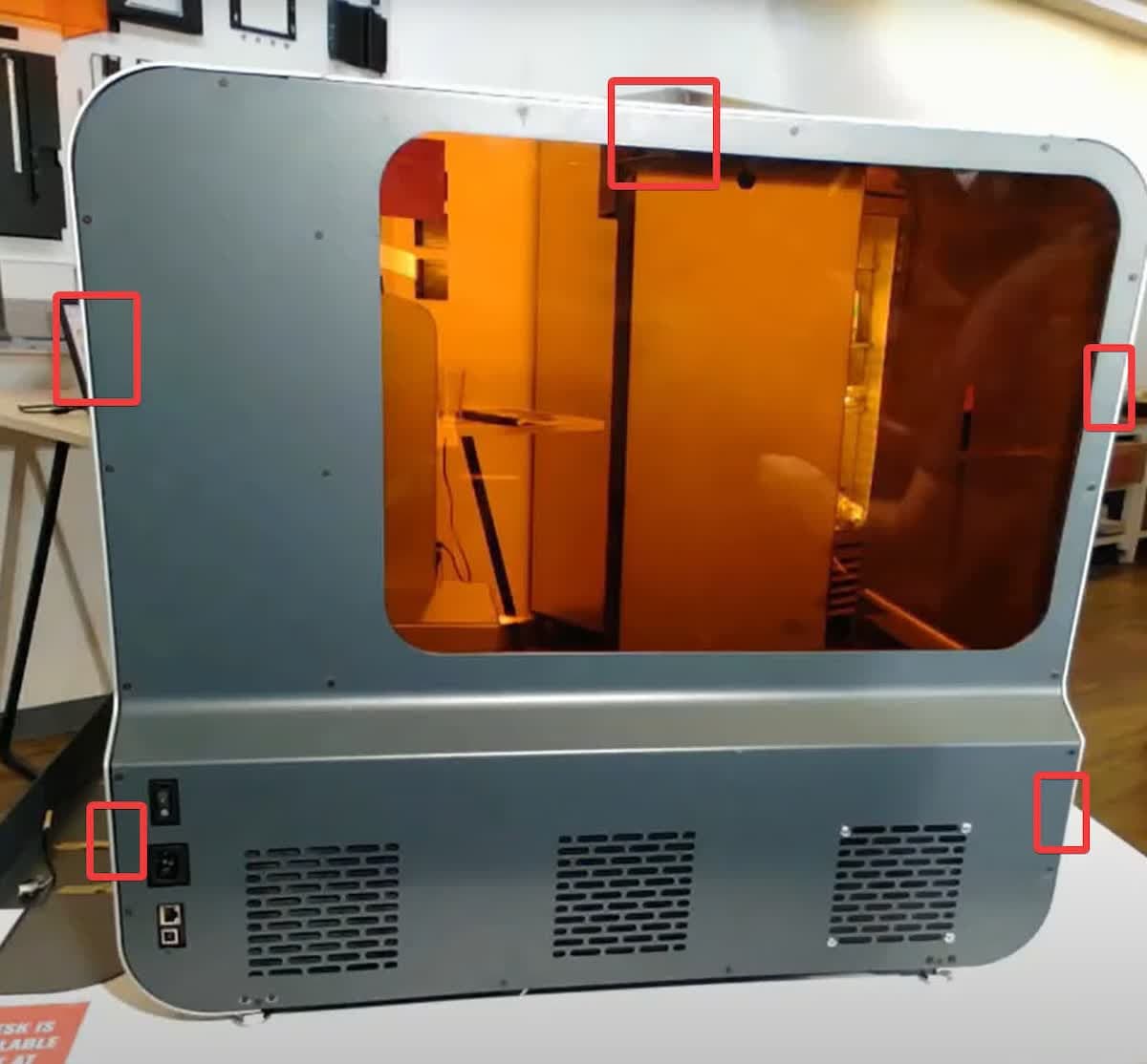
Remove the rear shell by pulling it away from the printer. There are five pins that hold the panel in place, so it may require moderate force to separate from the printer. Be careful not to damage the rear fan cable, which is still attached to the rear shell. Lay the rear shell down next to the printer.

f3l-rear-shell-pins.jpg

Step 4: Disconnect the rear fan

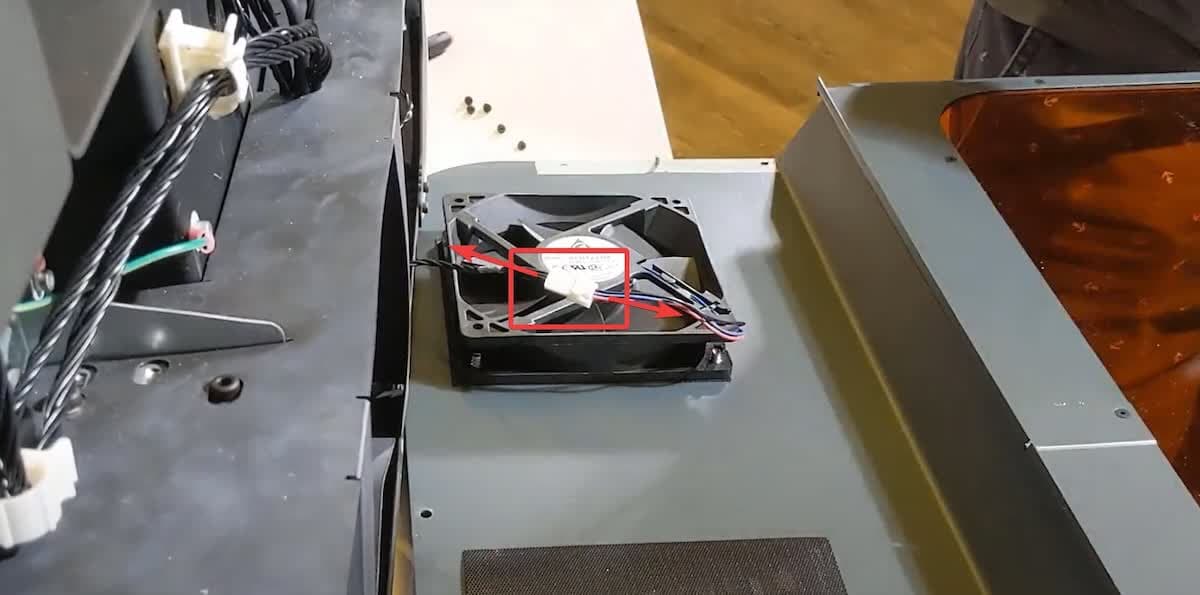
Disconnect the rear fan cable harness by gripping the plugs and gently pulling them away from each other. Do not pull on the wires themselves.

f3l-rear-shell-unplug-cable.jpg

Step 5: Remove the cartridge floor tray

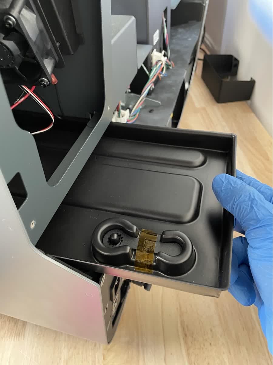
The cartridge floor tray is a plastic tray that sits beneath the cartridge floors. After removing the rear shell, slide the cartridge floor tray out the back of the printer, noting its orientation.

f3l-cartridge-tray.jpg

Removing the display assembly and front shell

Overview: Remove the display assembly and front shell of the printer.

Step 1: Remove the display assembly and front shell

The cartridge floor wiring harnesses are located behind the display assembly. The display assembly and front shell must be removed to access the cartridge floor wiring harnesses.

To remove the display assembly and front shell, follow the instructions in the guide for Replacing the Form 3L display assembly.

Removing the cartridge floor

Overview: Unscrew, unplug, and uninstall the faulty cartridge floor.

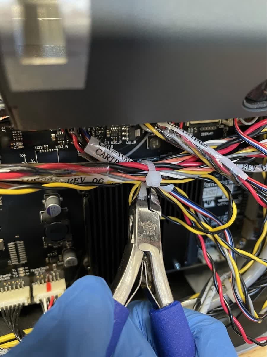
Step 1: Unbundle the cartridge floor cablesLocate and cut the cable tie bundling the group of wires near the motherboard.

f3l-cartridge-floor-cable-tie.jpg

Step 2: Disconnect the cartridge floor cables

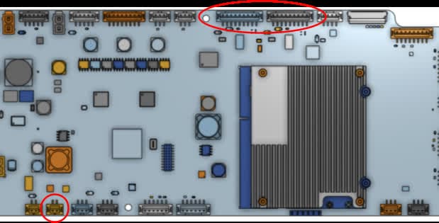
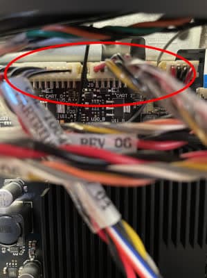
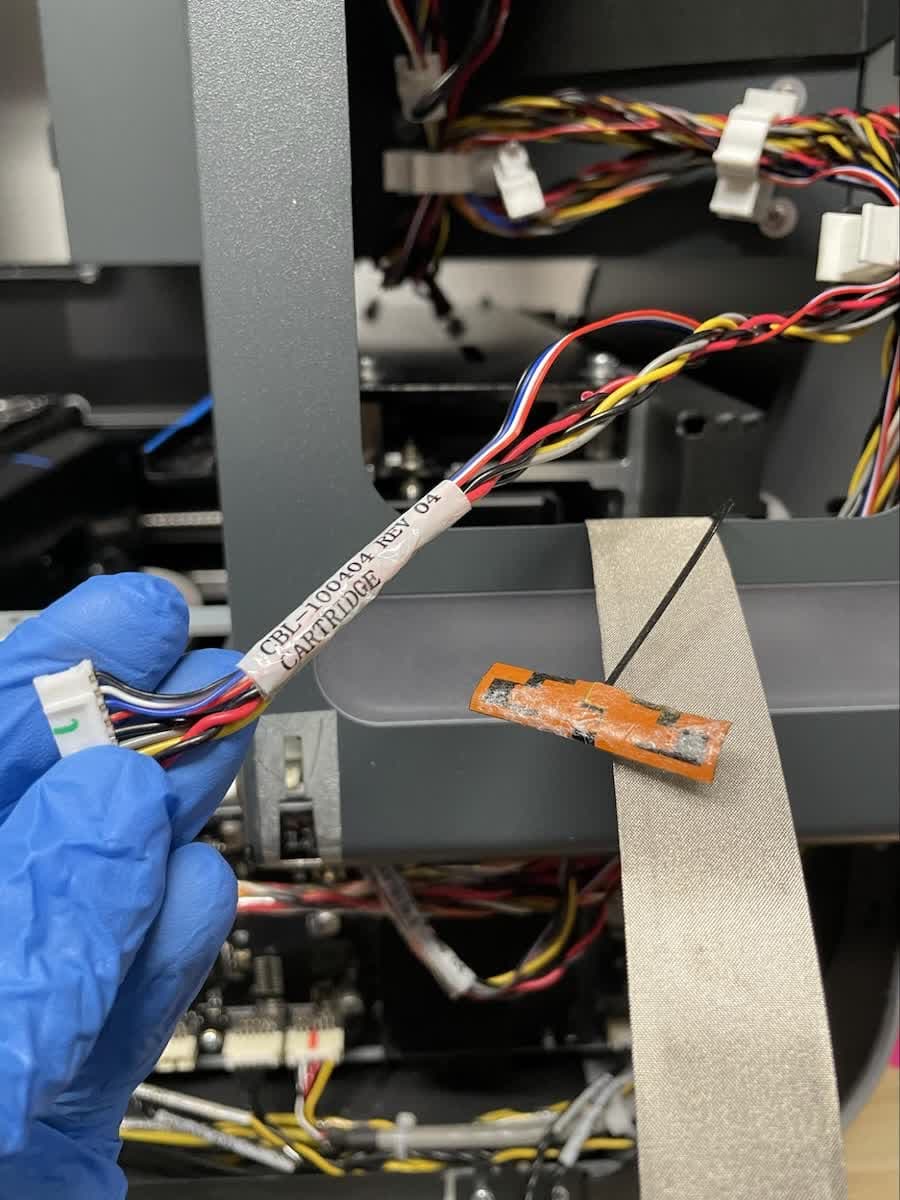
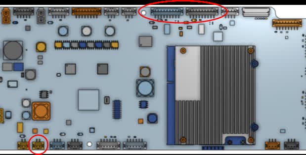
Locate the pins labeled CART 0 and CART 1, positioned toward the top of the motherboard. Label the respective cables with tape and a permanent marker to more easily distinguish them from one another.

f3l-cartridge-floor-cables-motherboard-1.jpg

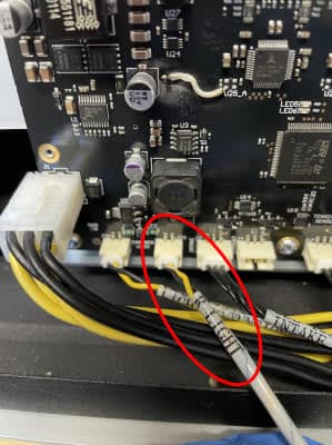
For both cables, hold the connector by its plastic housing and disconnect the cable from the motherboard. Do not pull on the individual wires. Also disconnect the cable labeled R LIGHT, located near the bottom-left corner of the motherboard. While this cable is not part of this service procedure, disconnecting it makes it easier to remove the cartridge floor.

f3l-cartridge-floor-cables-motherboard-2.jpg
f3l-cartridge-floor-cables-motherboard-3.jpg

Step 3: Route the cables behind the display assembly cutout

Using both hands, route all three cables upward so they can be reached through the cutout for the display assembly for easier access

f3l-cartridge-floor-cable-routing.jpg

Step 4: Remove the cables from the cable management clips

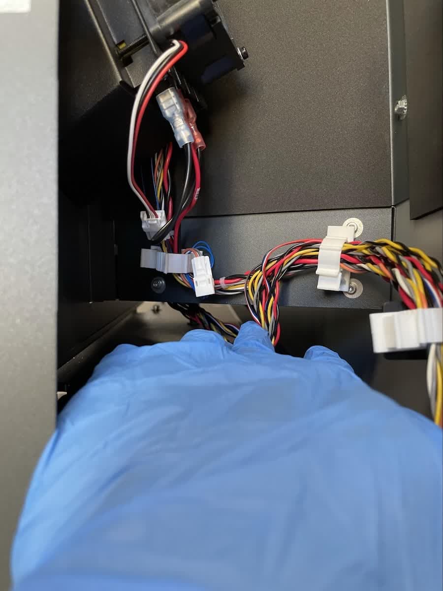
The CART 0, CART 1, and R LIGHT cables pass through a set of cable management clips, visible through the display assembly cutout. Press down on the tabs of the cable management clips to open them. Remove the three cables from all of the cable management clips. All cables leading to the cartridge floors should be free for removal and replacement of the cartridge floors.

f3l-cartridge-floor-cable-clips.jpg

Step 5: Remove the cartridge floor nuts

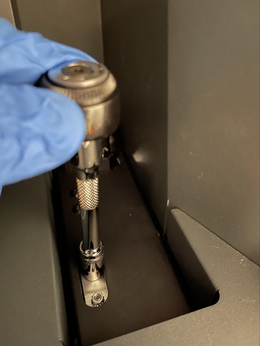
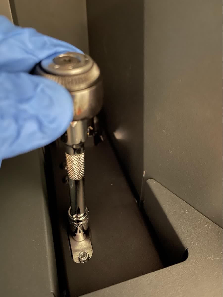
Move to the cartridge slots on the right side of the machine. Use the M3 (5.5 mm) socket wrench to loosen the two nuts accessible through the cutout in the cartridge floor that is being replaced. Remove the nuts and set them aside.

f3l-cartridge-floor-nuts.jpg

Step 6: Remove the cartridge floor

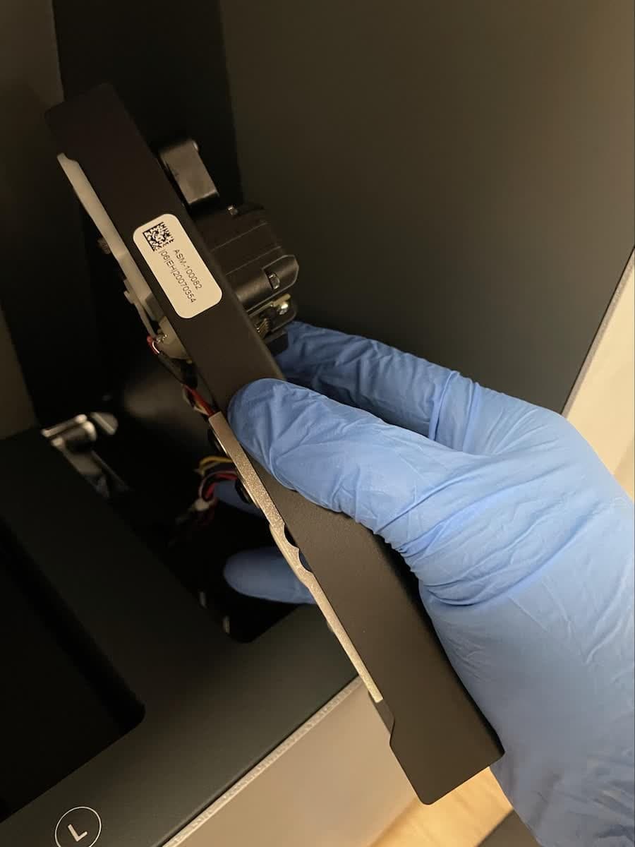
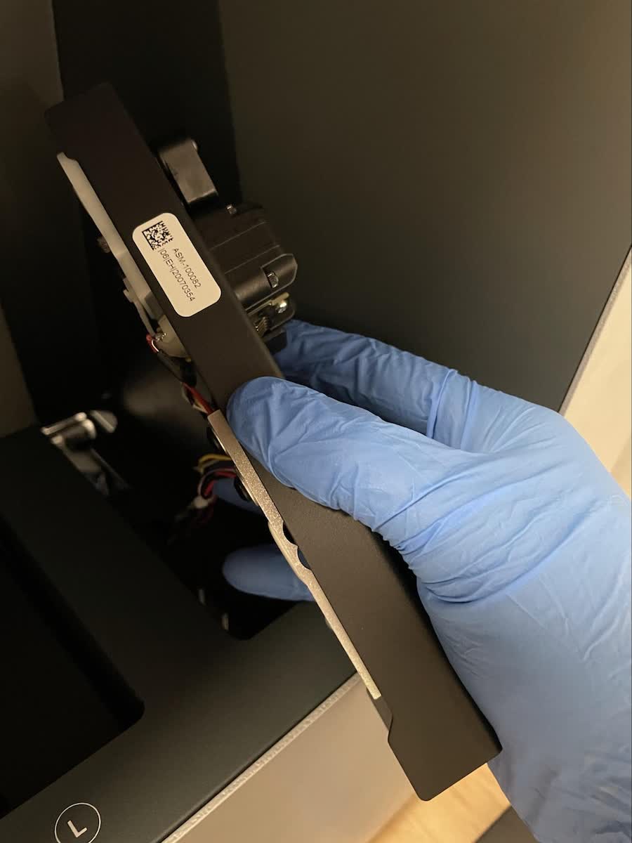
Grip the cartridge floor by the spring finger mount at the far end of the cartridge floor. Gently pull upwards on the cartridge floor with one hand while feeding the attached cable (CART 0 or CART 1) out with the other to prevent the cable from snagging. Set the cartridge floor aside.

f3l-cartridge-floor-standalone.jpg

Installing the new cartridge floor

Overview: Mount and secure the new cartridge floor.

Step 1: Mount the replacement cartridge floor

Label the replacement cartridge floor cable with tape and a permanent marker (CART 0 or CART 1).

NOTICE:

If you are replacing both cartridge floors, mount the right-hand cartridge floor first.

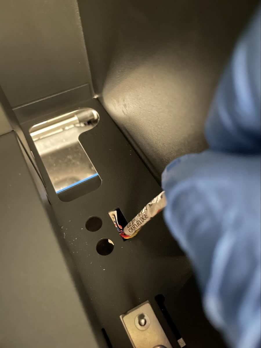
Feed the connector and cable down through the slot in the mount for the cartridge floor. Pull the cable through to the front of the machine. Align the screw posts on the mounting surface with the two holes in the cartridge floor. Place the cartridge floor on its mounting surface.

f3l-mount-cartridge-floor-1.jpg
f3l-mount-cartridge-floor-2.jpg

Step 2: Secure the replacement cartridge floor

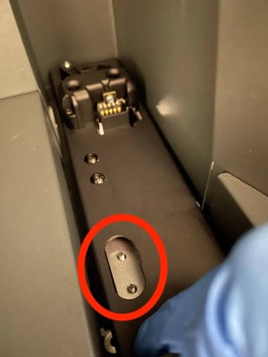
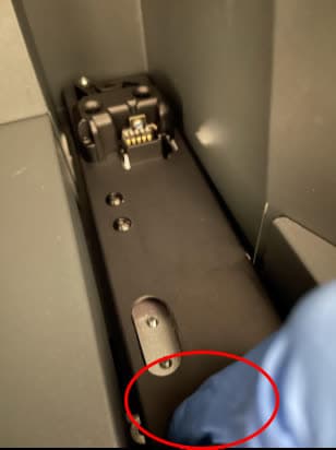
Push against the bottom-left of the cartridge floor to hold it straight and level. Avoid exerting force outside of this area. Place a washer and nut on each screw post. A pair of precision tweezers may be helpful for inserting and aligning the nuts and washers. Tighten the nuts loosely using the M3 (5.5 mm) socket wrench. Leave the nuts loose enough to be able to adjust the position of the cartridge floor.

f3l-mount-cartridge-floor-3.jpg
f3l-cartridge-floor-nuts.jpg

Step 3: Adjust the position of the cartridge floor

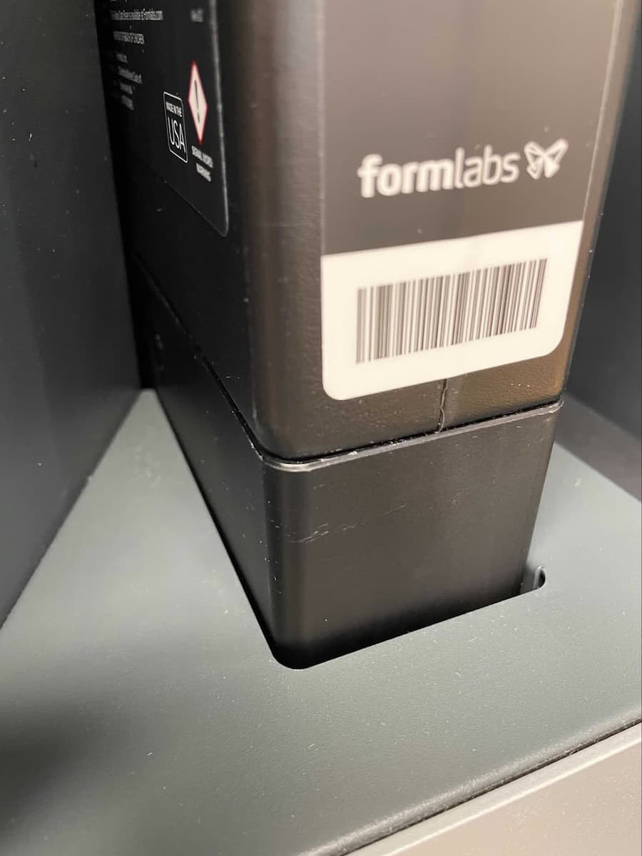
Place a resin cartridge onto the cartridge floor and verify that the cartridge does not touch any adjacent walls. If the cartridge is touching any walls, gently wiggle the cartridge and cartridge floor such that it is no longer in contact with any walls.

Once the cartridge floor is properly aligned, remove the cartridge and fully tighten the two cartridge floor nuts using the M3 (5.5 mm) socket wrench until snug. Re-insert the resin cartridge and verify the cartridge floor alignment after tightening. If you are replacing both cartridge floors, repeat this step for the other cartridge floor.

f3l-cartridge-floor-test.jpg

Step 4: Route the cables back to the motherboard

Press down on the tabs of the cable management clips to open them. Insert the three cables (CART 0, CART 1, and R LIGHT) into all of the cable management clips and route them back to the motherboard, keeping the cables taut. To close each of the cable management clips, push down on the loop to engage the latch.

Step 5: Reconnect and secure the cables

Reconnect the three cables to their respective headers on the motherboard. The connectors will only plug into the headers in the correct orientation. Be careful not to bend the pins on the motherboard.

f3l-cartridge-floor-cables-motherboard-1.jpg

Use a cable tie to group the cables into a single bundle, as they were at the start of the procedure.

Reinstalling the front shell and display assembly

Overview: After performing any other maintenance procedures, reinstall and secure the front shell and display assembly.

Step 1: Install the front shell and display assembly

Reinstall the front shell and display assembly following the instructions in the guide for Replacing the Form 3L display assembly.

Reinstalling the rear shell

Overview: Replace the cartridge floor tray and reinstall and secure the rear shell.

Step 1: Reinstall the cartridge floor tray

Slide the cartridge floor tray into the back of the printer in the same position and orientation it was initially in.

Step 2: Connect the rear fan

Lay the rear shell down behind the printer. Reconnect the two ends of the rear fan cable. Secure the fan cable to the rear shell with a strip of polyimide tape.

Step 3: Replace the rear shell

Place the rear shell back onto the printer, taking care to align the five pins on the shell with their respective holes. Press it towards the front of the printer to ensure that it fully seats in place. There should be no gaps between the rear shell and the side or bottom shells.

Step 4: Secure the rear shell

Using a T8 or T10 Torx driver, screw the 21 screws into the rear of the printer.

f3l-rear-shell-pins.jpg

Finalizing the repair

Overview: After reinstalling the rear shell, power on the printer and perform final checks.

Step 1: Power on the printer

Close the printer cover and connect the power cable to the printer and the power supply. The printer will initialize.

Step 2: Test the repair

Start a print to test the replacement cartridge floor. Monitor the printer to ensure that the cartridge floor detects the resin cartridge and dispenses resin properly. Contact Formlabs Support or your authorized reseller to share the results of the procedure.