
必要な備品:
- 2mm六角ドライバー(Form 4Lツールキャップアセンブリに付属)
- #2プラスドライバー
- ESD対応のスパッジャーまたはESD対応のピンセット
- ベンチトップリワークステーション、ホットリワークピンセット、その他のSMDはんだ付け装置
- はんだ吸い取り器
- はんだ付けフラックス
- ニトリル手袋
- 静電気防止用アースストラップ

Form Cure L V2のマザーボードにはWi-Fiモジュールが搭載されていますが、ソフトウェアによって無効化されており、マシンのインターフェースから有効化することはできません。お使いの組織のセキュリティ要件によっては、マシンを使用する前にWi-Fiハードウェアを物理的に取り外す必要がある場合があります。
Form Cure L V2のWi-Fiハードウェアのすべてに関するガイドです。
必要な備品:
推定所要時間: 30~45分
作業スペースを用意する
概要: Form Cure L V2と作業スペースを、マザーボードの交換作業ができる状態に準備します。
ステップ1:作業スペースを準備する
マシンの周りに作業スペースを確保します。作業スペースはよく換気された埃のない場所に確保してください。
ステップ2:マシンの電源プラグを抜く
本体背面の電源スイッチで電源を切ります。メンテナンスを続行する前に、プリンタに接続されている電源ケーブルを抜きます。マシンの電源ケーブルをコンセントに繋いだままメンテナンス作業を行わないでください。マシンの電源を切って5分ほど待ってから作業を開始してください。マシンを使用したばかりであれば、二次硬化チャンバーは温かくなっています。チャンバー内が冷えるまで少なくとも10分間待ちます。
危険:
電源ケーブルが接続された状態でマシンのメンテナンスを行うと、感電のリスクが高まります。マシンのパネルを取り外す際は、必ず電源ケーブルをコンセントから抜いてから作業してください。パネルを外している間は、絶対にマシンの電源を再投入しないでください。
マザーボードの取り外し
概要: マザーボードのケーブルを外し、取り外します。
ステップ1:ドアを開ける
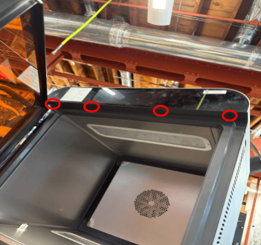
二次硬化チャンバーのドアを開け、前面パネルを固定しているネジにアクセスします。
ステップ2:マザーボードとディスプレイアセンブリのネジを外す
2mmの六角ドライバーを使って、マザーボードとディスプレイアセンブリをマシンのフレームに固定している4本のネジを緩めて取り外します。外したネジは脇に置いておきます。
ステップ3:マザーボードとディスプレイアセンブリを取り外す
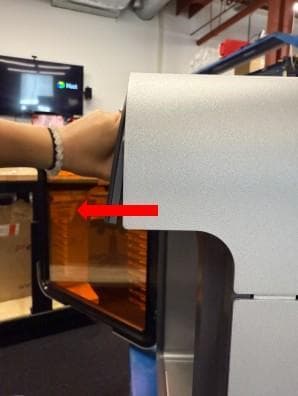
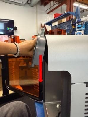
マザーボードとディスプレイアセンブリをゆっくりと上に傾け、下に引きます。アセンブリがマシンのフレームから外れます。マザーボードとディスプレイアセンブリはケーブルでForm Cure L V2に接続されているため、強く引っ張らないでください。
ステップ4:マザーボードのケーブルを外す
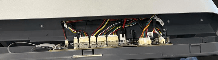
2本のリボンケーブルを除き、マザーボードからすべてのケーブルを外します。それぞれのコネクタのタブを押し、ケーブルをコネクタからスライドさせて外します。ワイヤー自体を引っ張らないようにご注意ください。
マザーボードとディスプレイアセンブリをマシンから完全に取り外し、作業台の上に置きます。
ステップ5:ディスプレイケーブルを外す
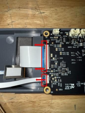
Form Cure L V2のディスプレイは、2本のリボンケーブルでマザーボードに接続されています。どちらの場合も、コネクタのロックタブをケーブルの方向にスライドさせます。タブが正しく解除されると、ケーブルは最小限の力でコネクタからスライドして外れます。リボンケーブルを損傷したり、急に引っ張ったりしないように注意してください。
ステップ6:マザーボードを取り外す
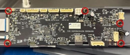
#2のプラスドライバーを使って、マザーボードをディスプレイに固定している5本のネジを緩めて取り外します。外したネジは脇に置いておきます。マザーボードを静電気対策済みの作業台に置きます。
マザーボードの改造
概要: マザーボードをマシンから取り外した後、マザーボードからWi-Fiコンポーネントを取り外します。
ステップ1:マザーボードの交換準備をする
まだ装着していない場合は、静電気防止リストバンドを装着し、既知の接地ポイントに接続します。リストバンドを、パウダーコーティングや塗装が施されている表面に接続しないでください。ホットリワーク用のピンセットまたは適切なSMDはんだ付け装置、および必要な個人用保護具を用意します。
ステップ2:Wi-Fiモジュールを無効化または取り外す
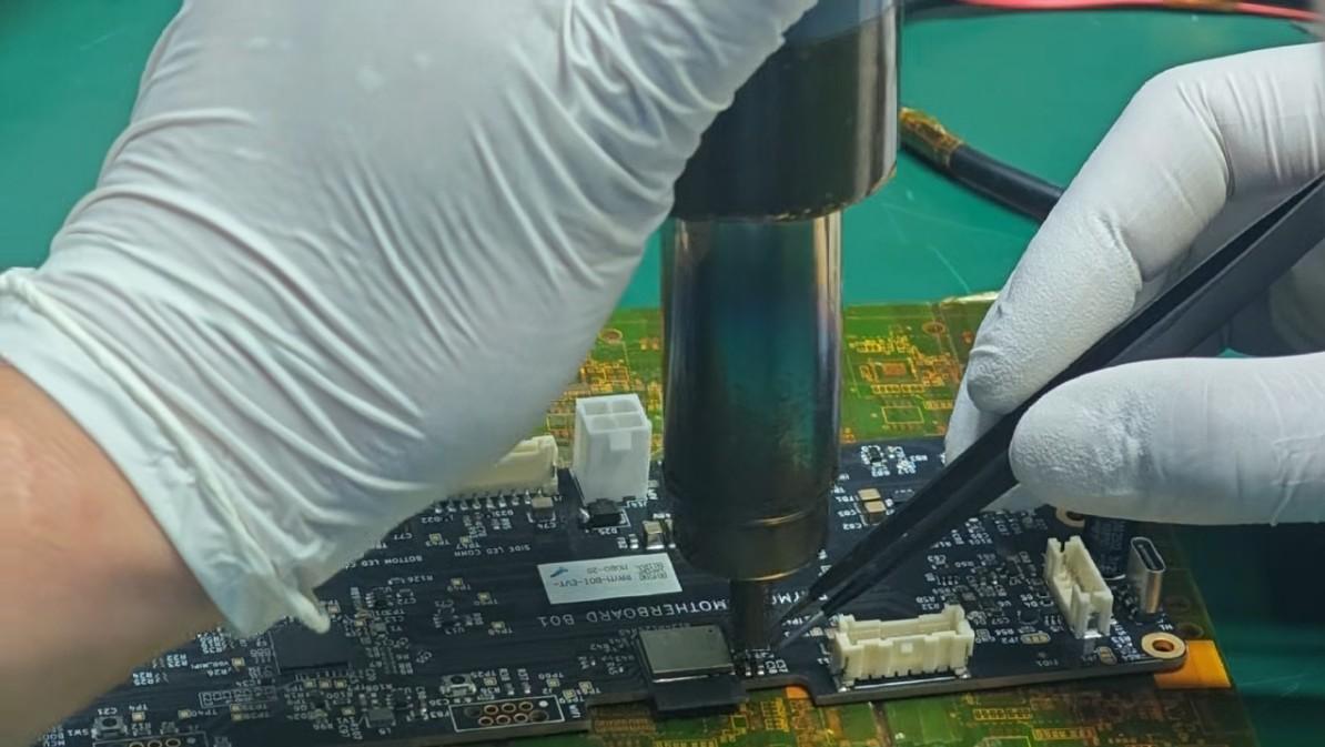
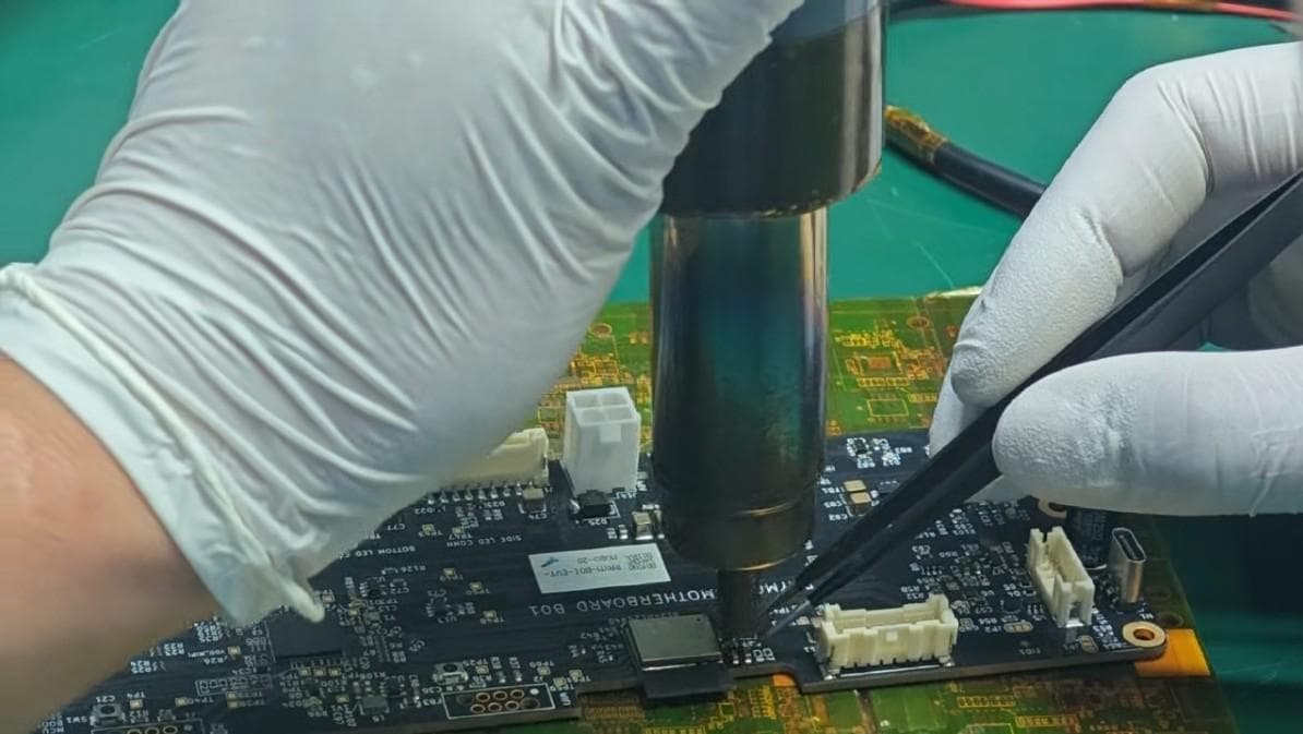
Wi-Fiモジュールと関連する抵抗(R39と表示)を見つけます。抵抗器を取り外してWi-Fiモジュールを電気的に無効にするか、抵抗器とWi-Fiモジュールの両方を完全に取り外すことができます。
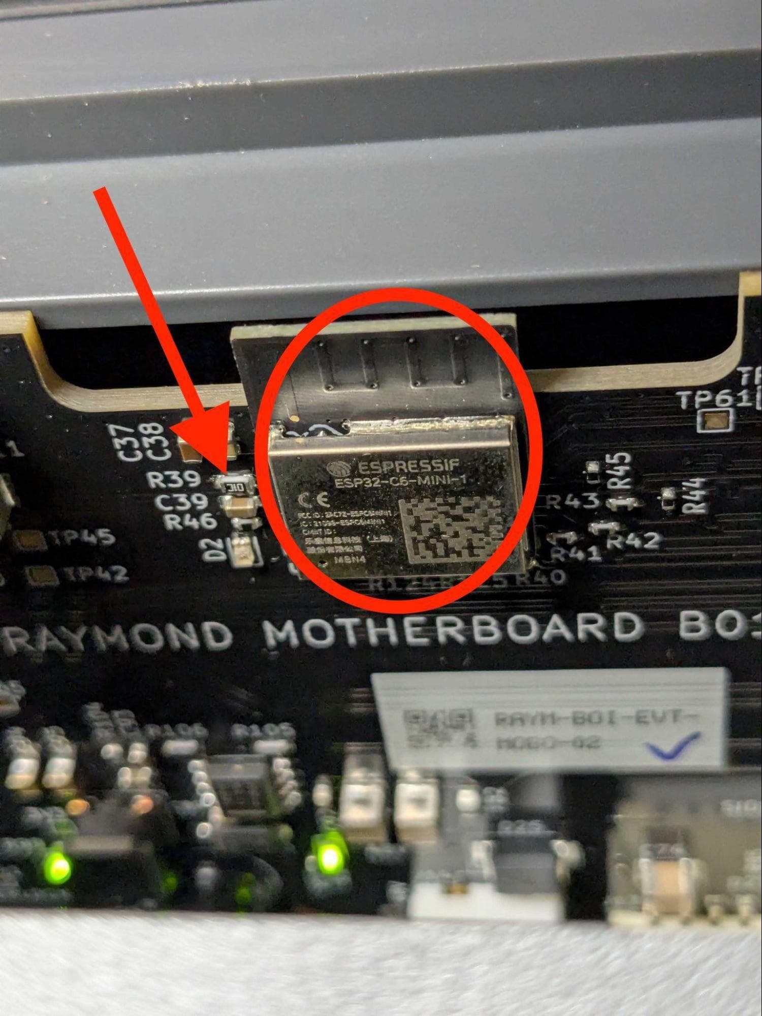
最良の結果を得るために、ベンチトップリワークステーション(300~350℃)、ESD対応のピンセット、はんだ吸取器、はんだフラックスを使用してください。はんだ付けした箇所にフラックスを塗布します。エアノズルをパッドの真上2~3cmの位置に置き、両端のはんだ付け部を均等に加熱します。はんだが溶けたら、ピンセットで抵抗器を慎重に取り外し、パッドに残ったはんだをはんだ吸取器で取り除きます。
将来この手順を元に戻す予定がある場合は、取り外した部品を R39 ESD保護袋に入れて保管してください。必要に応じて、Wi-Fiモジュール本体も同様に取り外します。
マザーボードの再装着
概要: マザーボードの改造後、ディスプレイに取り付けます。
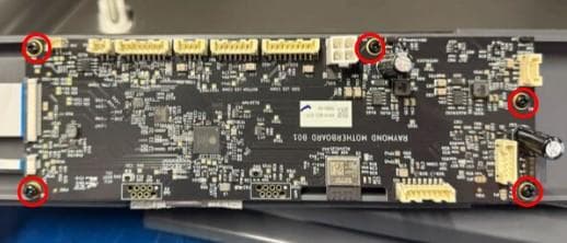
マザーボードをディスプレイの背面に置き、マザーボードの5つのネジ穴をディスプレイアセンブリの対応する穴に合わせます。
マザーボードの5つの穴に取り付けネジを1本ずつねじ込みます。#2のプラスドライバーを使用して、ネジをしっかりと締め付けます。
ステップ 3:リボンケーブルを接続して固定する
リボンケーブルをマザーボードのコネクタにスライドさせます。ケーブルが均等に挿入されていることを確認します。青いマークが上を向くようにします。ロックタブをコネクタの方向にスライドさせ、リボンケーブルを固定します。
マザーボードとディスプレイアセンブリの再装着
概要: マザーボードとディスプレイアセンブリを接続し、取り付けて固定します。
ステップ1:マザーボードのケーブルを接続する
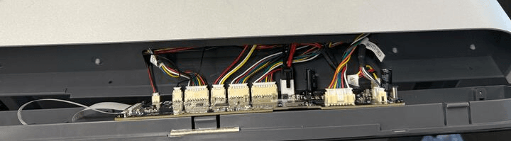
マザーボードとディスプレイアセンブリをマシンの前面、取り付け位置の近くで持ちます。下の画像を参考に、すべてのケーブルをマザーボードに再接続します。各ケーブルは、正しい向きでのみコネクタに接続できます。ケーブルが完全に接続されると、ロックタブがカチッと音を立てて固定されます。
ステップ2:マザーボードとディスプレイアセンブリを取り付ける
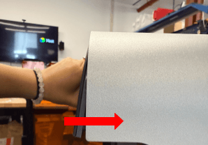
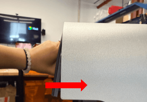
マザーボードとディスプレイアセンブリを少し上に傾けます。上部パネルの前端の下に差し込み、アセンブリの下部を所定の位置に傾けます。マザーボードとディスプレイアセンブリの底部にある4つのネジ穴が、Form Cure L V2の対応する穴と合っていることを確認します。
ステップ3:マザーボードとディスプレイアセンブリを固定する
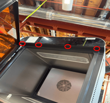
マザーボードとディスプレイアセンブリの底面にある4つのネジ穴に、取り付けネジを1本ずつねじ込みます。2mmの六角ドライバーを使って、ぴったりとはまるまでネジを締めます。
手順の最終確認を行う
概要: マザーボードとディスプレイアセンブリを再装着した後、最終チェックを行います。
ステップ1:マシンの電源を入れる
電源ケーブルをマシンと電源に接続します。本体背面のスイッチをオンにします。
ステップ2:手順をテストする
Form Cure L V2の各機能をテストし、正常に動作することを確認します(Wi-Fi接続を除く)。