
Required Supplies:
Formlabs:
- X-axis limit switch
- 2.5 mm hex driver
Third-party:
- Nitrile gloves
Optional supplies:
- 3 mm hex driver
- 2 mm hex driver
- T10 Torx driver

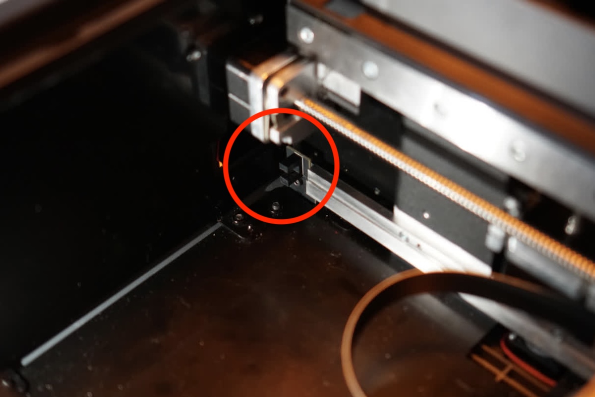
The printer uses the X-axis limit switch to detect that the Light Processing Unit (LPU) has reached the left end of the printer cavity. If the X-axis limit switch is damaged or malfunctioning, the LPU may not move properly and the printer may display an error message.
Use this guide to remove and replace the Form 3 X-axis limit switch.
Required Supplies:
Formlabs:
Third-party:
Optional supplies:
Estimated time: 10–20 minutes
DANGER:
Read and follow all safety instructions and warnings in the operator manual. Replacement with incorrect parts can lead to burns, shock, fire, or explosion. Dispose of all parts in accordance with local regulations.
Preparing the workspace
Overview: Prepare the Form 3 and a dust-free workspace for replacing the X-axis limit switch.
NOTICE:
The X-axis limit switch is a sensitive electronic component. Do not remove the X-axis limit switch from its packaging until instructed.
Step 1: Remove the build platform
Remove the build platform first to avoid dripping resin into the printer cavity.
Step 2: Remove the resin cartridge
Remove the resin cartridge and close the vent cap to prevent resin from dripping off of the bite valve and into the printer.
Step 3: Remove and store the resin tank
Remove the resin tank, place it in the resin tank case, and cover it with its lid. Set the case and tank aside on a clean, flat surface.
NOTICE:
Wear gloves and hold the resin tank by the tank grips on either side to avoid contamination or damage to the underside of the tank.
Step 4: Prepare the workspace
Clear a workspace around your printer. Ensure that the workspace is well-ventilated and free of dust.
Step 5: Clean the printer cavity
WARNING:
Resin may cause skin irritation or an allergic skin reaction. Wear gloves when handling liquid resin or resin-coated surfaces. Wash skin with plenty of soap and water.
Open the printer cover. Clean any resin pooled on the printer floor, inside the printer cavity, with paper towels. Dampen the paper towels with isopropyl alcohol if necessary to fully remove the resin.
DANGER:
IPA is flammable and presents a fire hazard. Keep containers closed, and keep out of the reach of children.
Step 6: Unplug the printer
Disconnect the power cable before continuing with maintenance. Do not perform maintenance on the printer while it is connected to power. Wait five minutes after disconnecting the printer from power before proceeding.
DANGER:
Performing maintenance on the printer while it is plugged in increases the risk of electric shock. Never remove the back panel of the printer while the printer is plugged in. Never reconnect the printer to power while the back panel is uninstalled.
Removing the rear shell (optional)
Overview: The X-axis limit switch can be replaced without disassembling any other parts of the printer. However, removing the rear shell of the printer will give you more space to work and allow access to both sides of the switch.
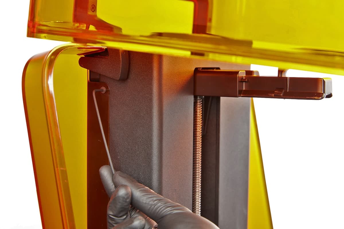
Open the printer cover. There is one screw on each side of the Z-tower. Depending on the age of your printer, they may be 2 mm hex screws or T10 Torx screws. Use the appropriate driver to loosen and remove the two screws on the side of the Z-tower.
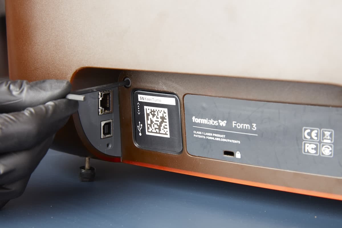
Rotate the printer to access the rear. Use a 3 mm hex driver to loosen and remove the two screws on the back of the printer, near the power and data ports.
Step 3: Remove the rear shell
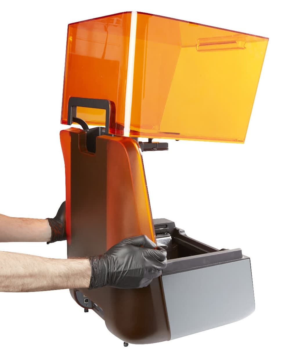
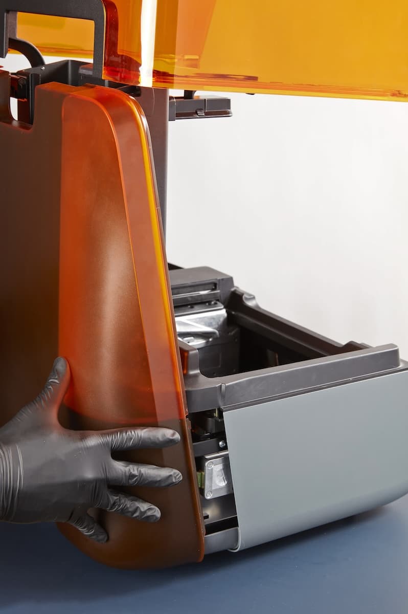
Gently flex the sides of the rear shell outwards to unclip it from the printer frame. Pull the rear shell directly away from the printer to remove it. Set the rear shell aside.
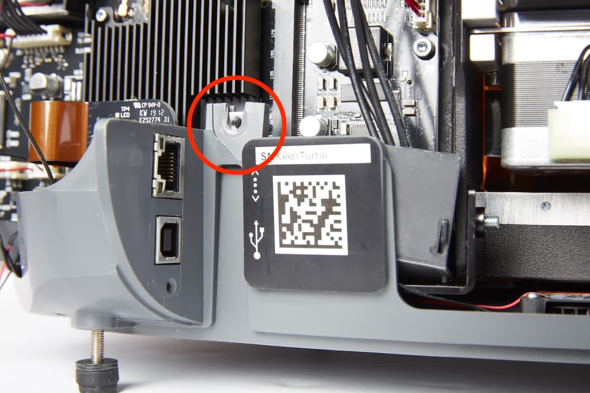
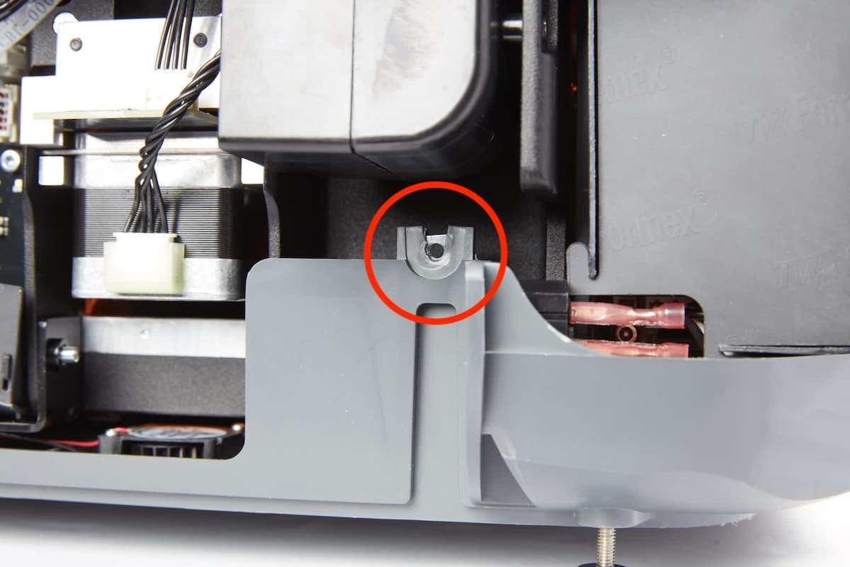
Locate—but do not remove—the two nuts, retained in the lower shell, that previously secured the external rear shell screws. Ensure that they did not come loose while removing the rear shell.
Removing the X-axis limit switch
Overview: Unplug and remove the damaged X-axis limit switch.
NOTICE:
The Form 3 contains sensitive electronic components. Ground yourself before touching any electronics in the printer by using a grounding strap or touching a grounded piece of metal.
Using the 2.5 mm hex driver, loosen the single screw holding the limit switch circuit board to the printer frame. This screw may be screwed in tightly and require force to loosen. Make sure that you turn only the screw attached to the limit switch and not other screws nearby in the printer. Remove the screw from the printer and set it aside.
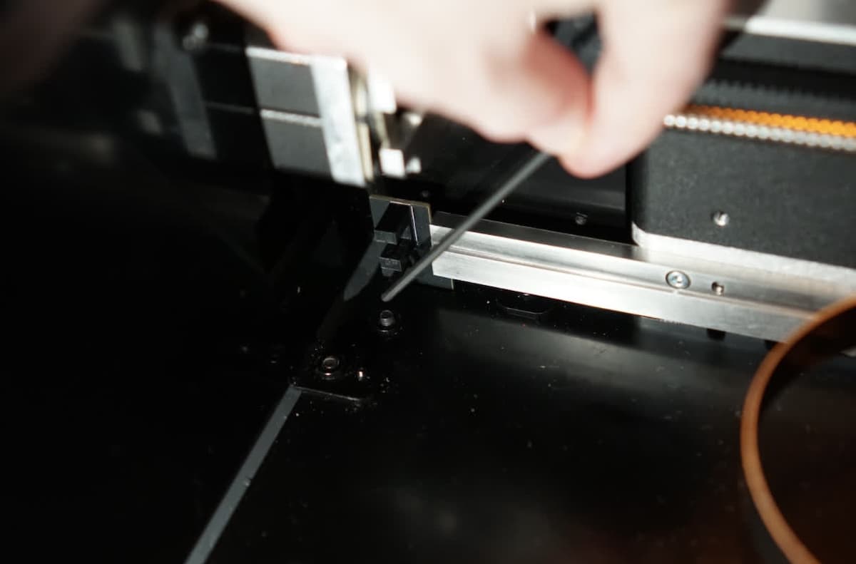
The limit switch is attached to the printer by its cable. To access the cable, move the limit switch toward the left wall of the printer, lift it upwards, and then pull it out toward the front of the printer.
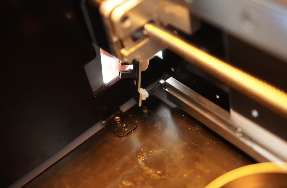
Step 3: Disconnect the X-axis limit switch cable
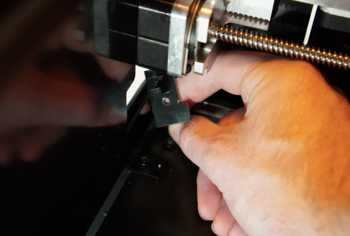
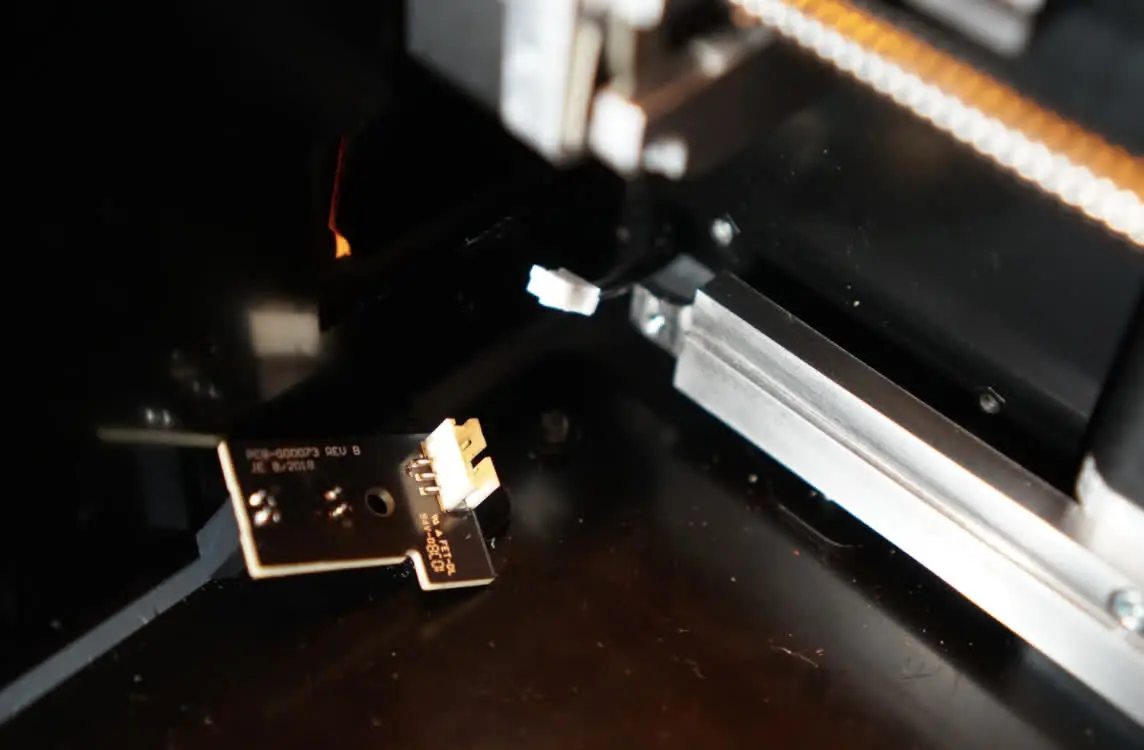
Locate the cable behind the X-axis limit switch. Hold the connector by its plastic housing and disconnect the cable from the X-axis limit switch. Do not pull on the individual wires.
Set the damaged switch aside. Do not let the unplugged cable fall down or back into the printer body as it may be difficult to retrieve.
Installing the new X-axis limit switch
Overview: After removing the old X-axis limit switch, connect and install the replacement X-axis limit switch.
Step 1: Reconnect the X-axis limit switch cable
Remove the replacement X-axis limit switch from its packaging. Grasp the X-axis limit switch cable, and push the new limit switch onto it to plug it in.
Step 2: Mount the X-axis limit switch
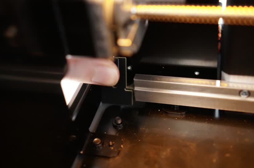
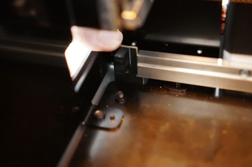
Push the limit switch back against the printer frame, then down into the gap in the printer’s floor. Then, move the switch to the right so that it sits flush with the metal rail on the back of the printer cavity. The “L” shape of the limit switch circuit board sits snugly against the corner of the metal rail and the screw hole in the circuit board aligns with the corresponding hole in the printer frame.
Step 3: Install the X-axis limit switch screw
Place the X-axis limit switch screw on the end of the 2.5 mm hex driver and insert it into the screw hole on the circuit board. Tighten the screw until finger tight.
Reinstalling the rear shell (optional)
Overview: If you previously removed the rear shell, reinstall it.
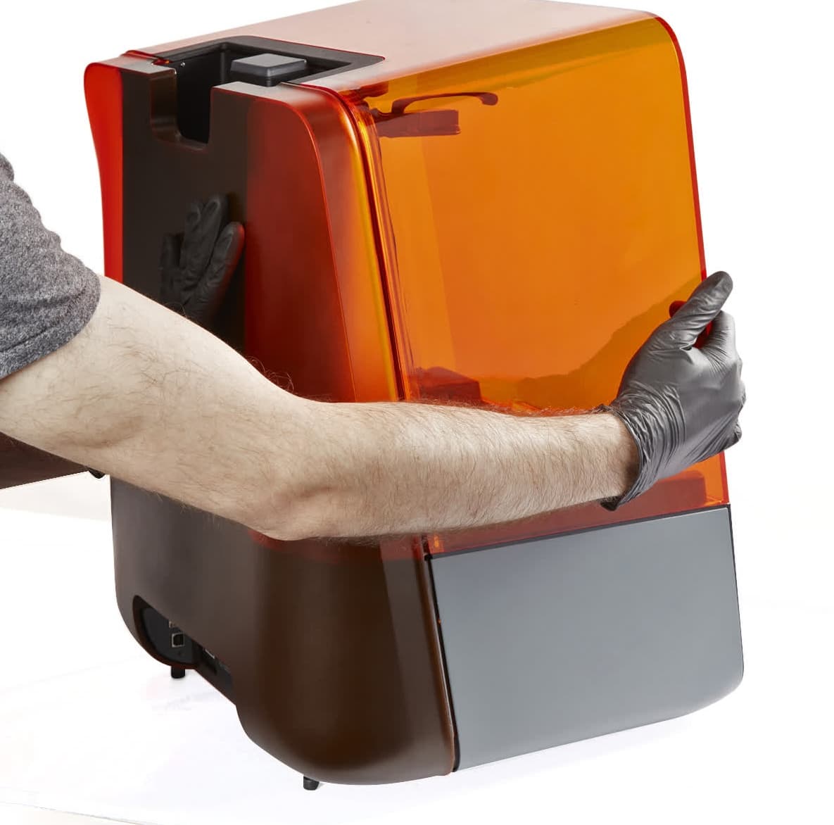
Place the rear shell back onto the printer. Press it towards the front of the printer to ensure that it fully seats in place. There should be no gaps between the rear shell and the side or bottom shells.
Using a 3 mm hex driver, screw the two 3 mm hex screws into the rear of the printer.
Open the printer cover. Using a 2 mm hex driver or a T10 Torx driver (depending on the type of screws in your printer), screw the two Z-tower screws into the sides of the Z-tower.
Finalizing the repair
Overview: After installing the new X-axis limit switch, power on the printer and perform final checks.
Step 1: Power on the printer
Close the printer cover and connect the power cable to the printer and the power supply. The printer initializes and the LPU moves across the printer cavity. Ensure that the LPU moves smoothly and reverses direction when it reaches the left side of the printer without any unusual noises or error messages.