
Required Supplies:
Formlabs:
- Form 4L motherboard
- 2.5 mm hex driver (included in the Form 4L tool caddy)
- 2 mm hex driver (included in the Form 4L tool caddy)
Third-party:
- Nitrile gloves
- ESD-safe tweezers

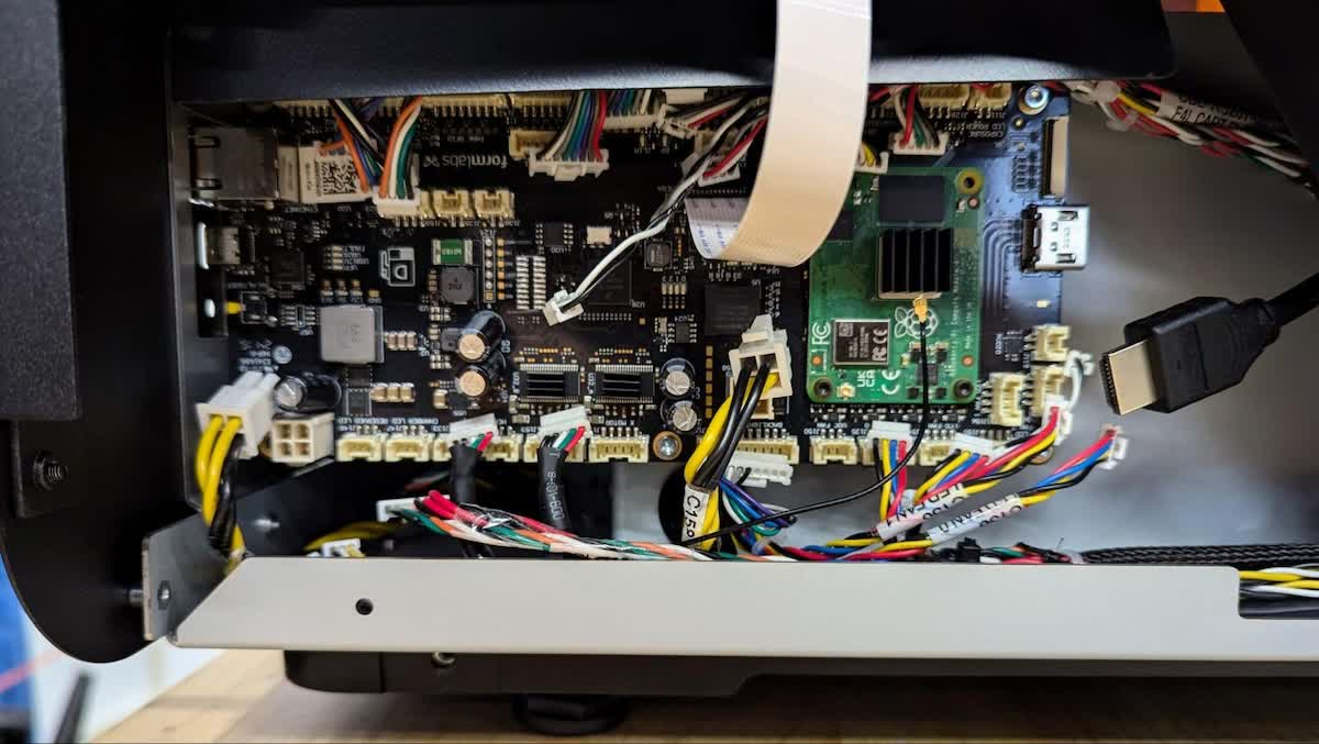
The motherboard is the main electronics module on the Form 4L that controls the various subsystems. A malfunctioning motherboard may prevent the printer from functioning properly.
Use this guide to replace the Form 4L motherboard.
Required Supplies:
Formlabs:
Third-party:
Estimated time: 30–45 minutes
Preparing the workspace
Overview: Prepare the printer and a dust-free workspace for replacing the motherboard.
Step 1: Remove the build platform
Remove the build platform first to avoid dripping resin onto the Light Processing Unit (LPU).
Step 2: Remove the resin cartridges
Remove the resin cartridges and close the vent caps to prevent resin from dripping off of the bite valves and into the printer.
Step 3: Remove and store the resin tank and mixer
Unlatch the mixer and resin tank. Remove the resin tank and cover it with its lid. Set the tank aside on a clean, flat surface.
NOTICE:
Wear gloves and hold the resin tank by the tank grips on either side to avoid contamination or damage to the underside of the tank.
Step 4: Prepare the workspace
Clear a workspace around your printer. Ensure that the workspace is well-ventilated and free of dust.
Step 5: Power down and unplug the printer
Turn the power switch off at the back of the printer. Disconnect the power cable before continuing with maintenance. Do not perform maintenance on the printer while it is connected to power. Wait five minutes after disconnecting the printer from power before proceeding.
Remove the side panel
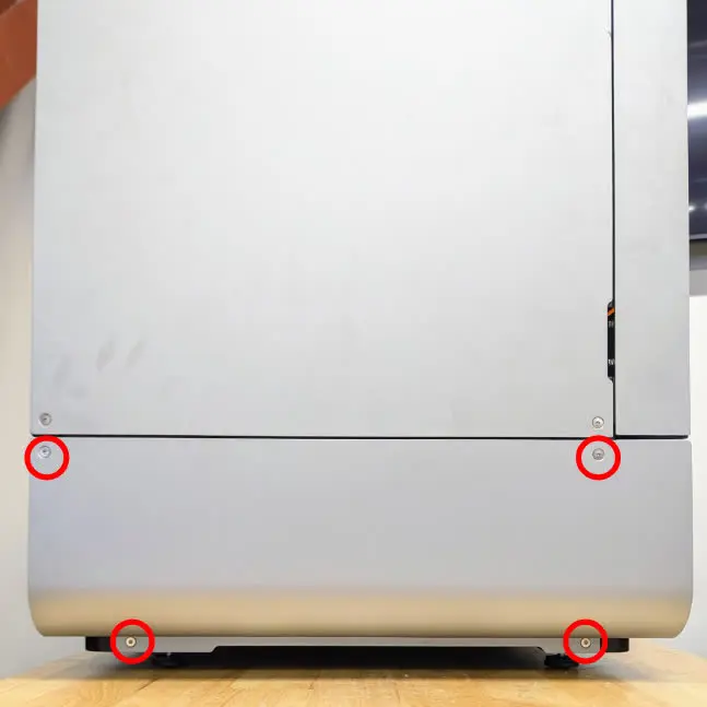
Overview: Remove the lower left side panel to access the motherboard.
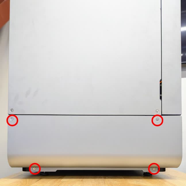
Use a 2.5 mm hex driver to remove the four screws that secure the lower left panel to the printer. Set the panel and the screws aside.
Disconnecting the cables
Overview: Disconnect all cables from the motherboard. The cables have numbered labels printed near their connectors.
NOTICE:
Take care when unplugging the cables to avoid damage. All cables can be easily removed with little force if the connector is properly released. Never pull by the wires or cables.
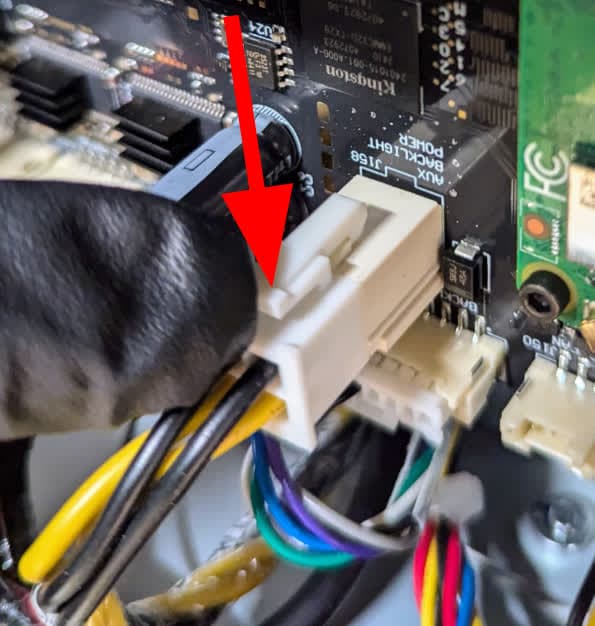
Disconnect the square white power cable connector by pushing down on the tab and sliding the cable out of the connector. Take care not to pull on the wires.
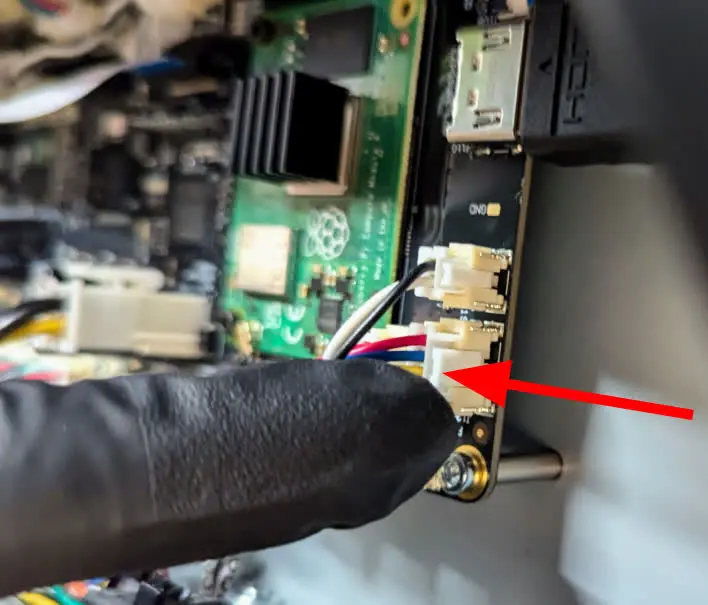
There are a number of rectangular white connectors around the periphery of the motherboard. These cables are for the motors, fans, Backlight Unit, Light Processing Unit, and other subsystems within the printer. Disconnect these connectors by pressing the tabs to release the latches.
Disconnect the camera ribbon cable by pulling on each side of the black connector tab to release the cable. Slide the ribbon cable out of the connector.
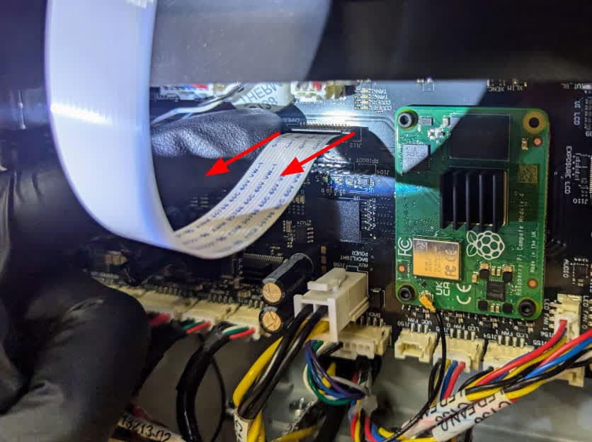
Disconnect the touchscreen ribbon cable by flipping the black tab away from the motherboard. Slide the ribbon cable out of the connector.
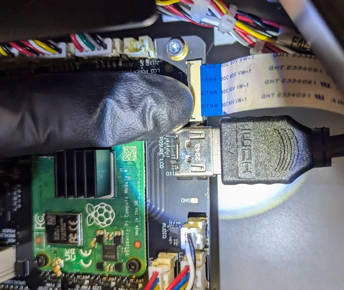
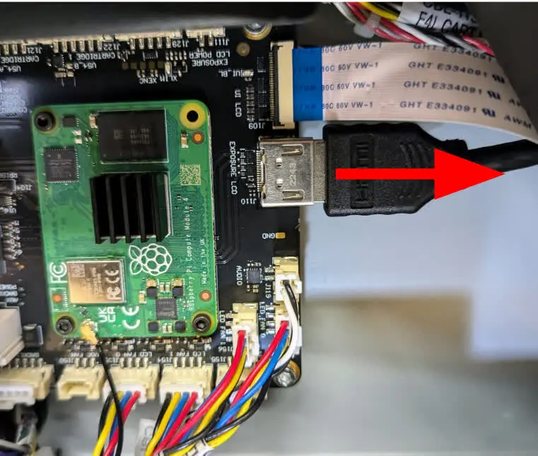
Disconnect the HDMI cable by pulling it away from the motherboard.
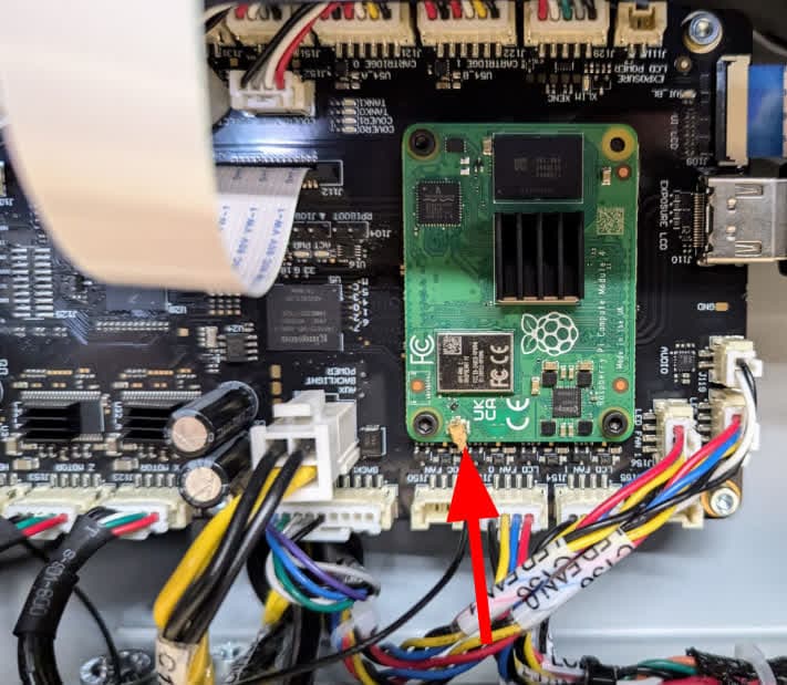
Using a pair of ESD-safe tweezers, disconnect the Wi-Fi antenna cable. Take care removing the Wi-Fi antenna cable, as it is extremely fragile and may bend or break if improperly handled.
Removing and replacing the motherboard
Overview: Remove the screws securing the motherboard to the printer and remove the motherboard, replacing it with the new one.
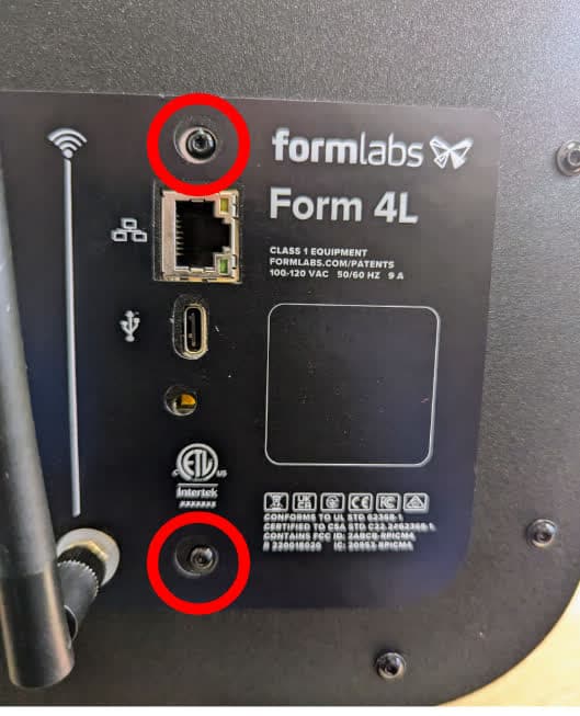
Use a 2 mm hex driver to remove the two hex screws located in the back of the printer that secure the motherboard to the rear panel. Set the screws aside.
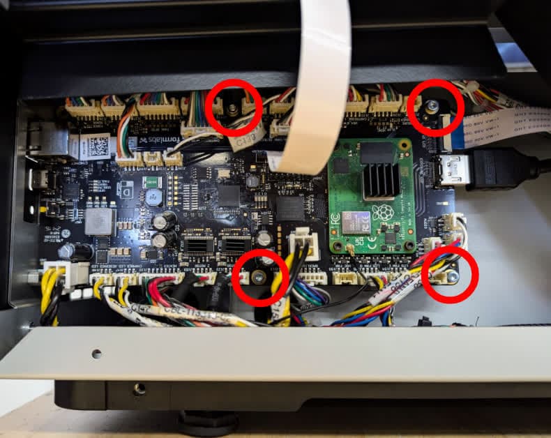
Use a 2.5 mm hex driver to remove the four screws that secure the motherboard to the printer. Set the screws aside.
Slide the motherboard out of the printer and set it aside for disposal with e-waste.
Slide the replacement motherboard into the printer. Make sure to position cables and connectors in front of the motherboard, and be careful not to pinch any cables during installation. Check that the Ethernet and USB ports on the left side of the motherboard are accessible through the cutouts in the back of the printer and that the screw holes in the motherboard align with those in the printer.
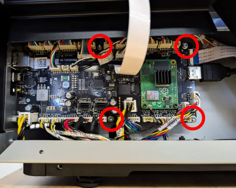
Use a 2.5 mm hex driver to install the four screws that secure the motherboard to the printer chassis. Tighten the screws until snug.
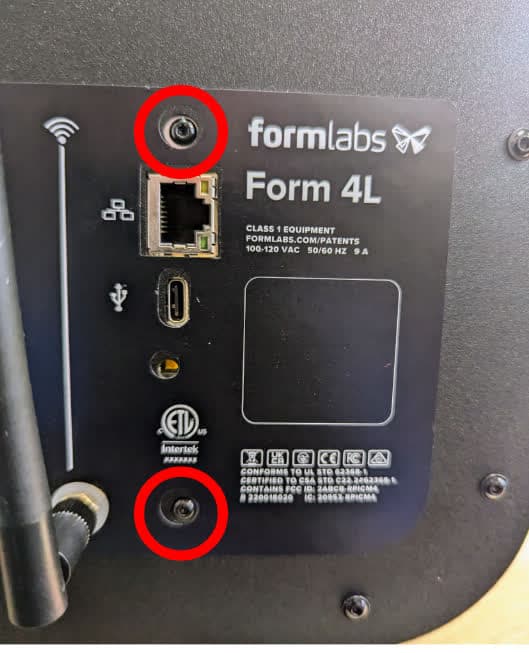
Use a 2 mm hex drive to install the two screws that secure the motherboard to the back panel. Tighten the screws until snug.
Reconnecting the motherboard cables
Overview: Connect all cables to the motherboard. The cables have numbered labels printed near their connectors.
Reconnect the two square white power connectors by aligning them and pressing until the latch clicks into place. Take care not to pull on the wires.
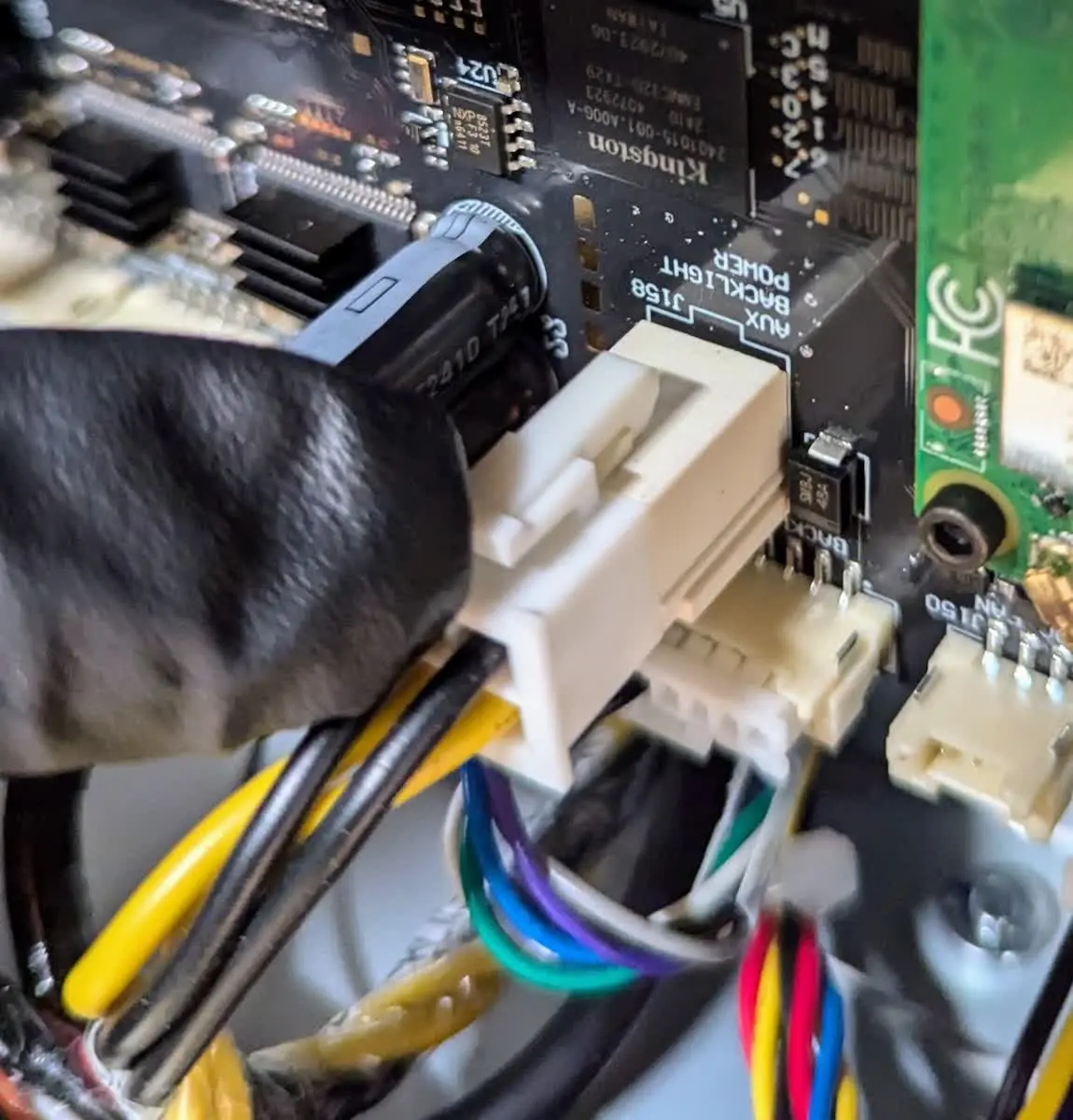
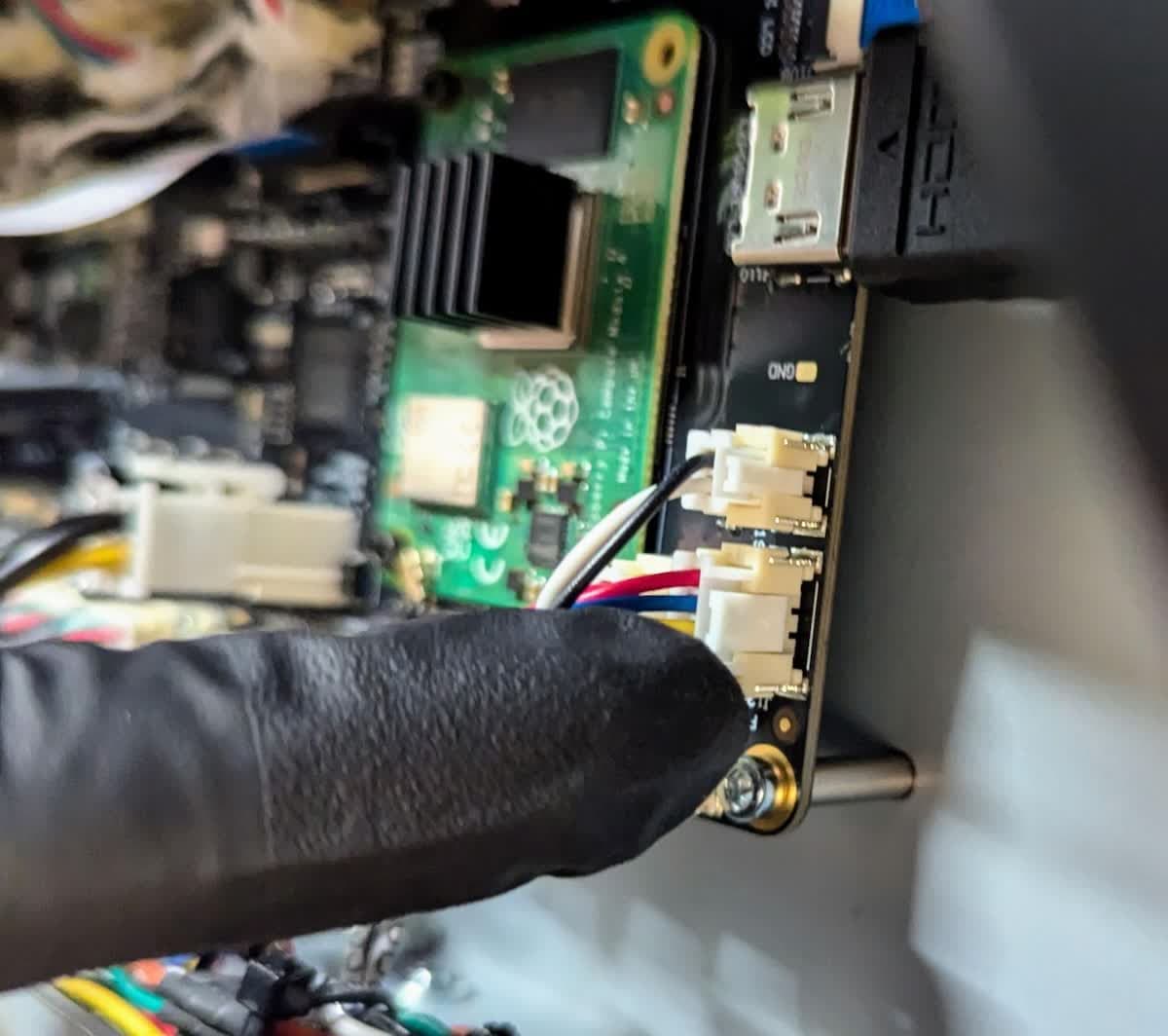
Reconnect the rectangular white connectors around the periphery of the motherboard by aligning them and pressing until the latch clicks into place. Each cable is numbered and corresponds to a printed label next to its connector.
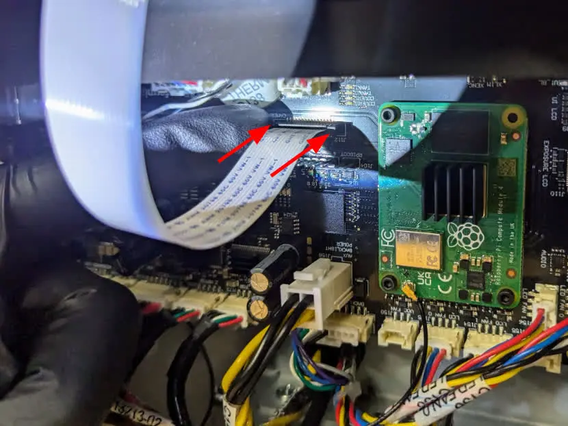
Slide the cable into the connector with the blue side down. Press each side of the black tab to secure the cable.
Reconnect the touchscreen ribbon cable by sliding the ribbon cable into the connector with the blue side visible. Flip the tab down to lock the ribbon cable in place.
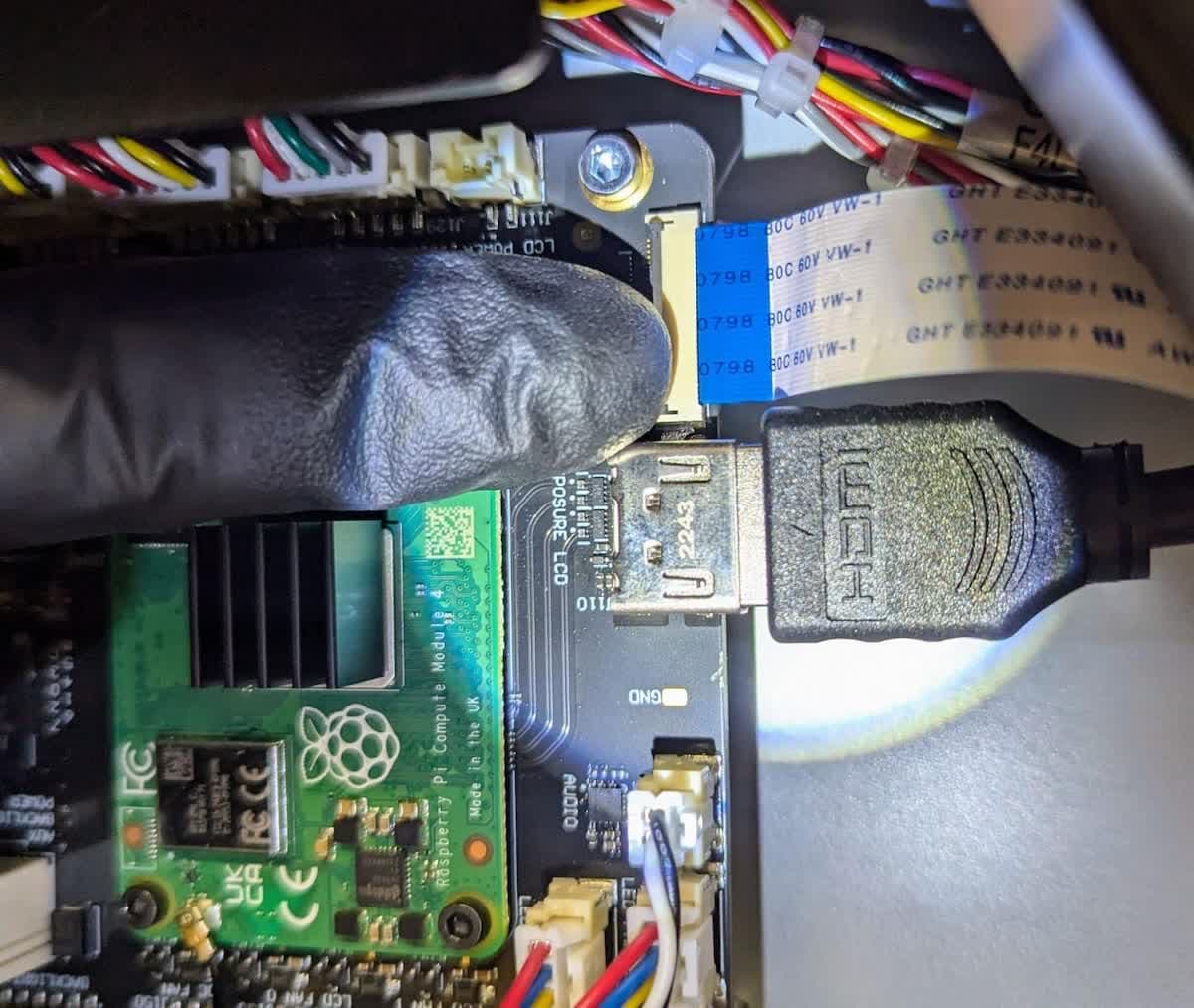
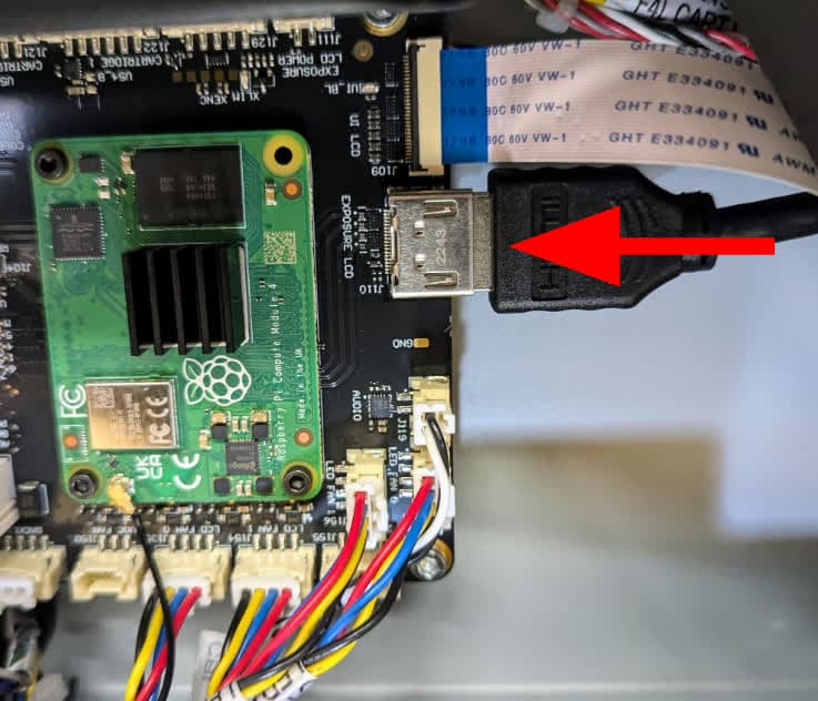
Insert the HDMI cable into the port.
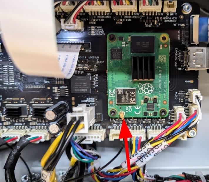
Reconnect the SOM antenna by pressing down on the gold-colored connector until it clicks into place.
Install the side panel
Overview: Reinstall the lower left side panel.
Use a 2.5 mm hex driver to install the four screws that secure the lower left panel to the printer. Tighten the screws until snug.
Finalizing the repair
Overview: After installing the new motherboard, power on the printer and perform final checks.
Step 1: Power on the printer
Close the printer cover and connect the power cable to the printer and the power supply. Turn on the switch at the back of the printer. The printer will turn on and initialize.
Step 2: Run a test print
Insert any missing consumables and upload and start a print. Check that the print starts normally and the parts print successfully. Contact Formlabs Support or your authorized reseller to share the results of the procedure.