
Required supplies:
Formlabs:
- System on module (SOM)
Third-party:
- 1.3 mm hex driver
- 1.5 mm hex driver
- 2.5 mm hex driver
- Nitrile gloves

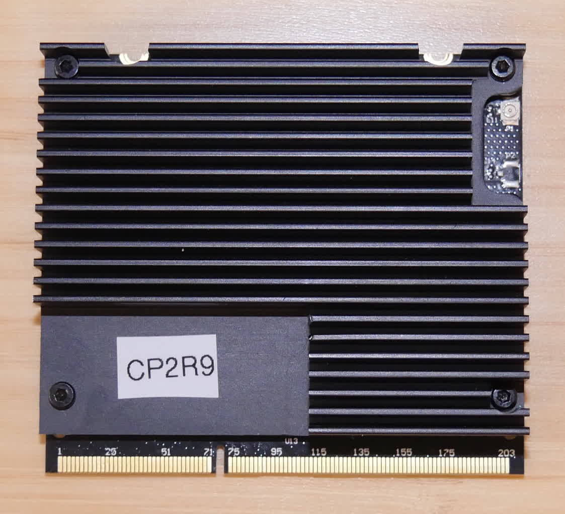
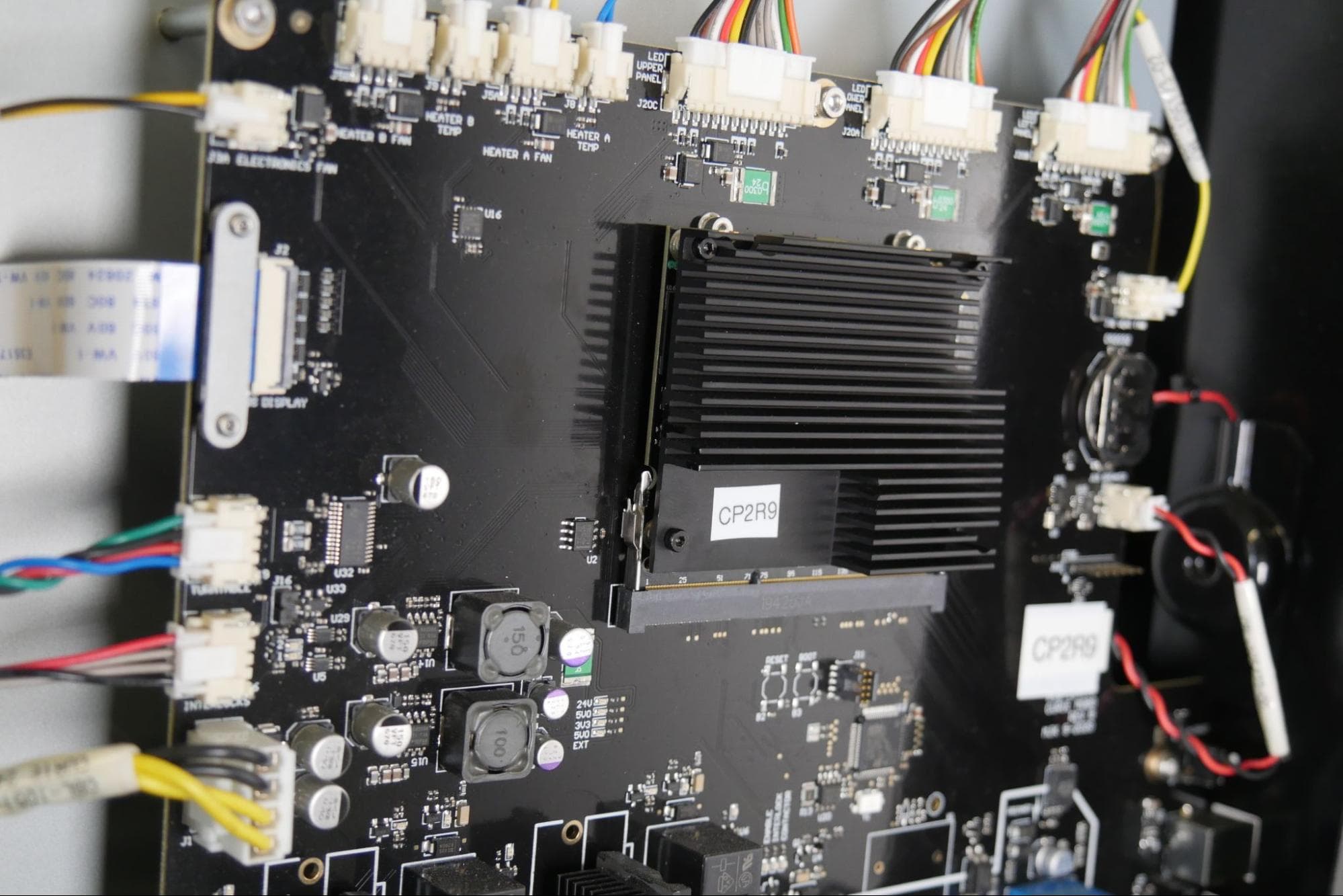
The Form Cure L V1 system on a module (SOM) plugs in to the motherboard and runs firmware on the machine. A malfunctioning SOM may cause the machine to freeze during initialization or fail to turn on.
Use this guide to replace the Form Cure L V1 SOM.
Required supplies:
Formlabs:
Third-party:
Estimated time: 20–30 minutes
Preparing the workspace
Overview: Prepare the Form Cure L and a dust-free workspace for replacing the SOM.
Step 1: Prepare the workspace
Clear a workspace around your machine. Ensure that the workspace is well-ventilated and free of dust.
Step 2: Unplug the machine
Disconnect the power cable from the machine before continuing with maintenance. Do not perform maintenance on the machine while it is connected to power. Wait five minutes after disconnecting the machine from power before proceeding.
Danger:
Performing maintenance on the machine while it is plugged in increases the risk of electric shock. Never remove the machine’s shells while it is plugged in. Never reconnect the machine to power while the shells are uninstalled.
Removing the top shell
Overview: Unscrew and remove the top shell from the Form Cure L to access the SOM.
Notice:
The Form Cure L contains sensitive electronic components. Ground yourself before touching any electronics in the machine by using a grounding strap or touching a grounded piece of metal.
Step 1: Unscrew the top shell retention screws
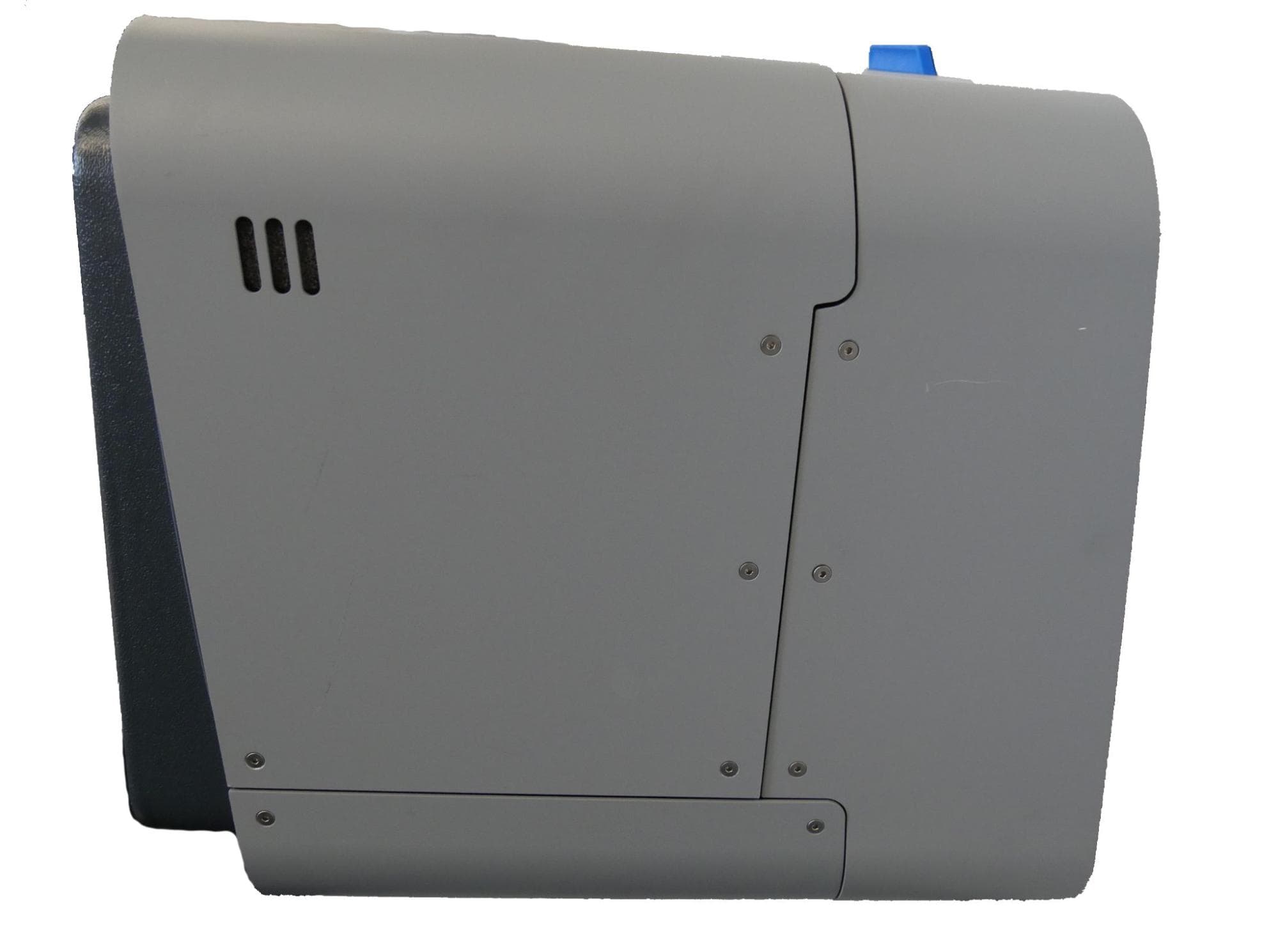
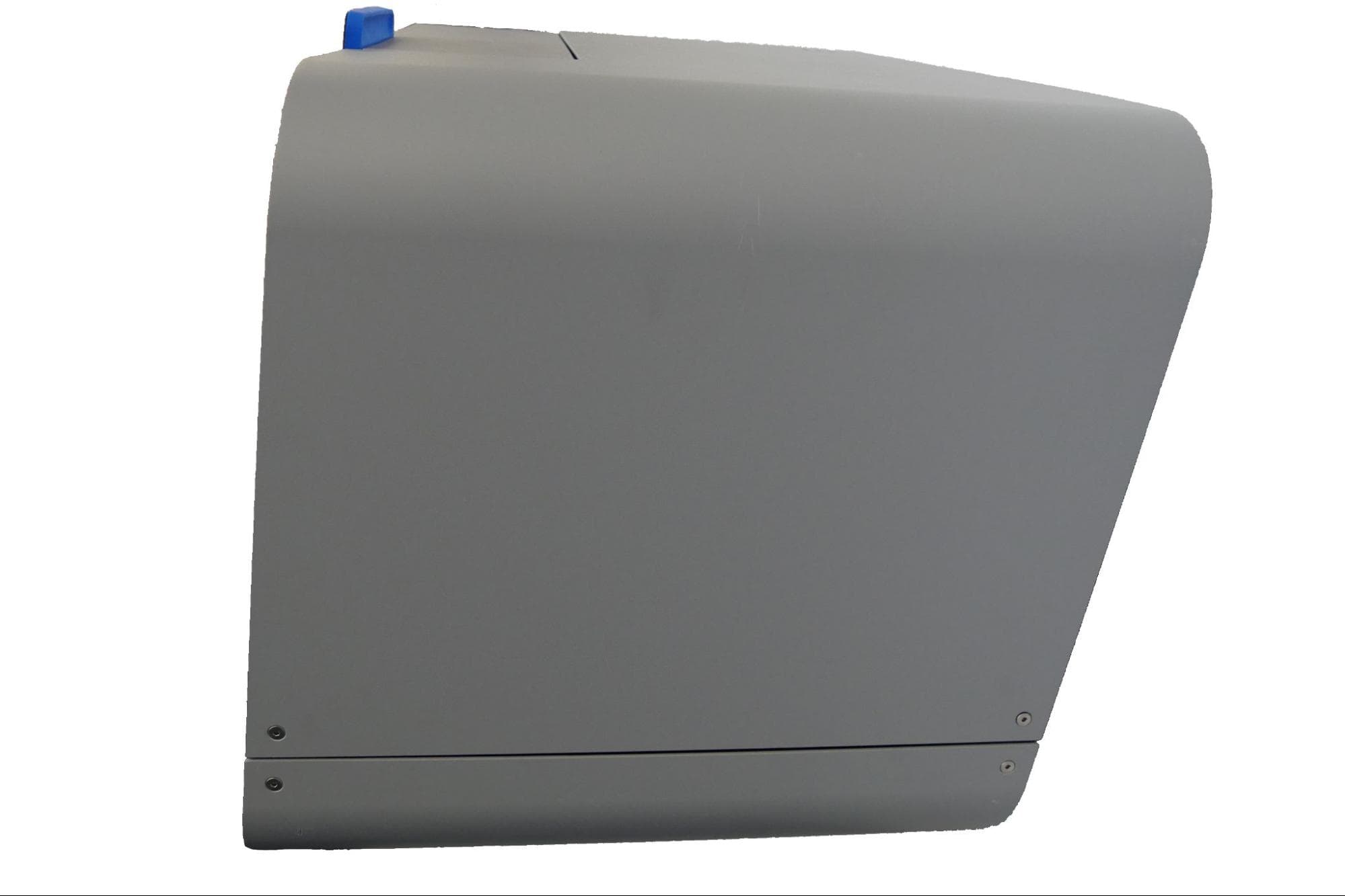
The top shell is secured to the frame of the machine with six hex screws. When facing the front of the Form Cure L, two screws are located on the right side and four are located on the left. Use a 2.5 mm hex driver to unscrew and remove the screws.
Step 2: Remove the top shell
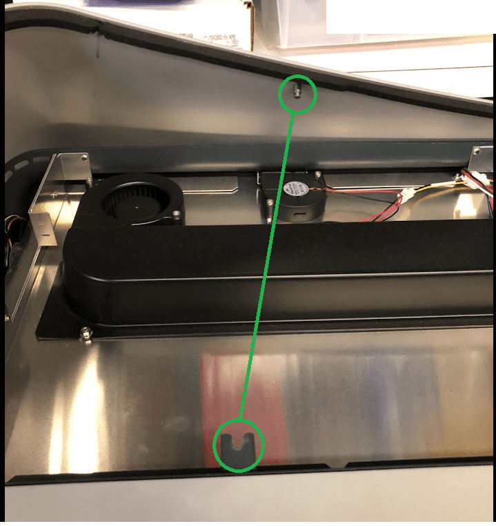
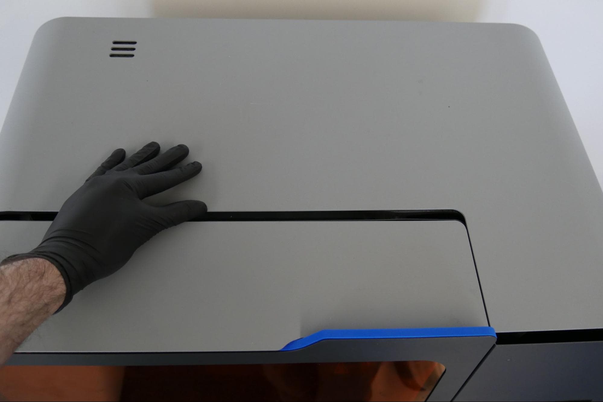
Slide the top shell towards the back of the machine to unhook it from the frame. Lift the top shell away from the machine and set it to the side.
Disconnecting the Wi-Fi antenna
Overview: Unplug the Wi-Fi antenna from the SOM.
Step 1: Disconnect the Wi-Fi antenna from the SOM
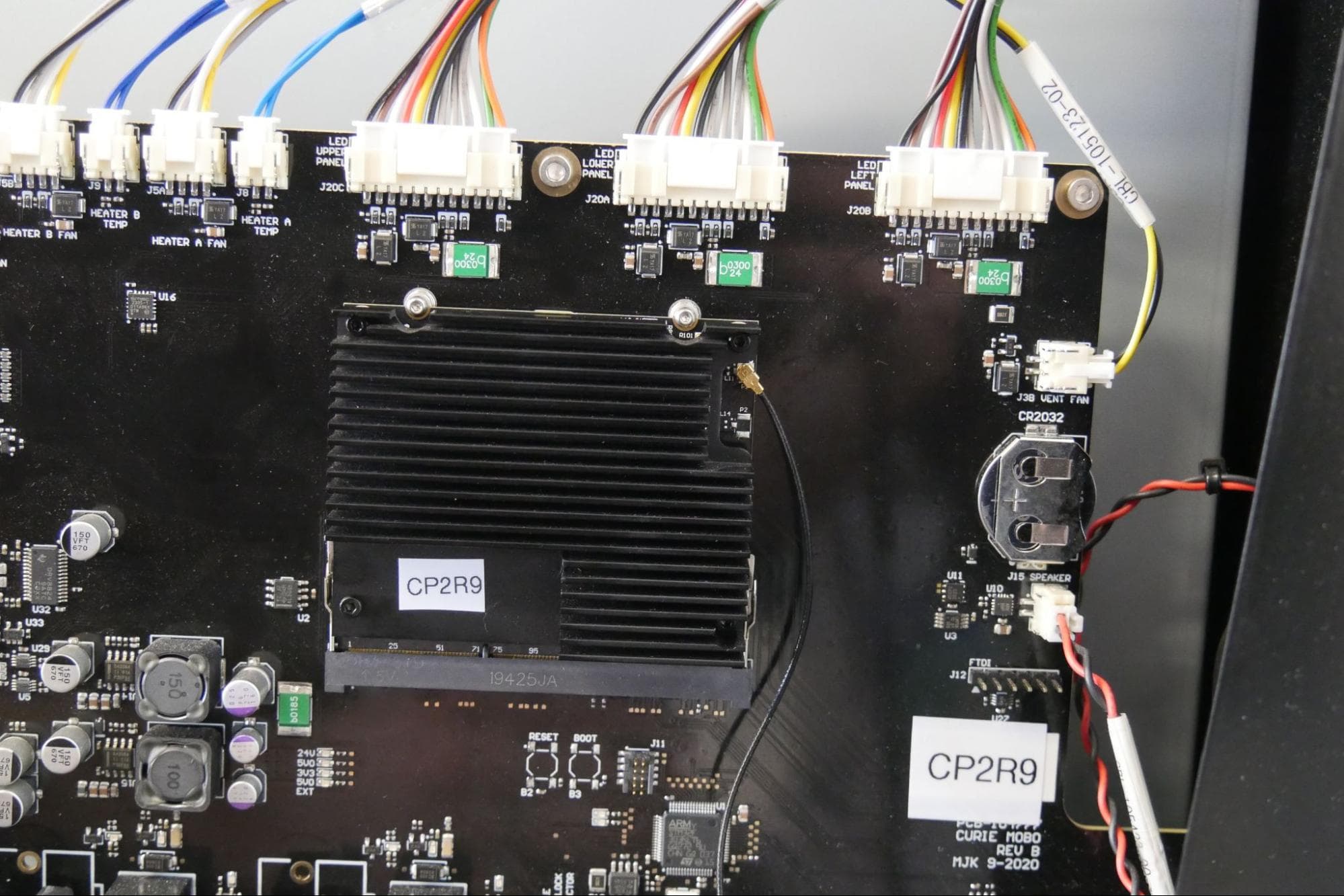
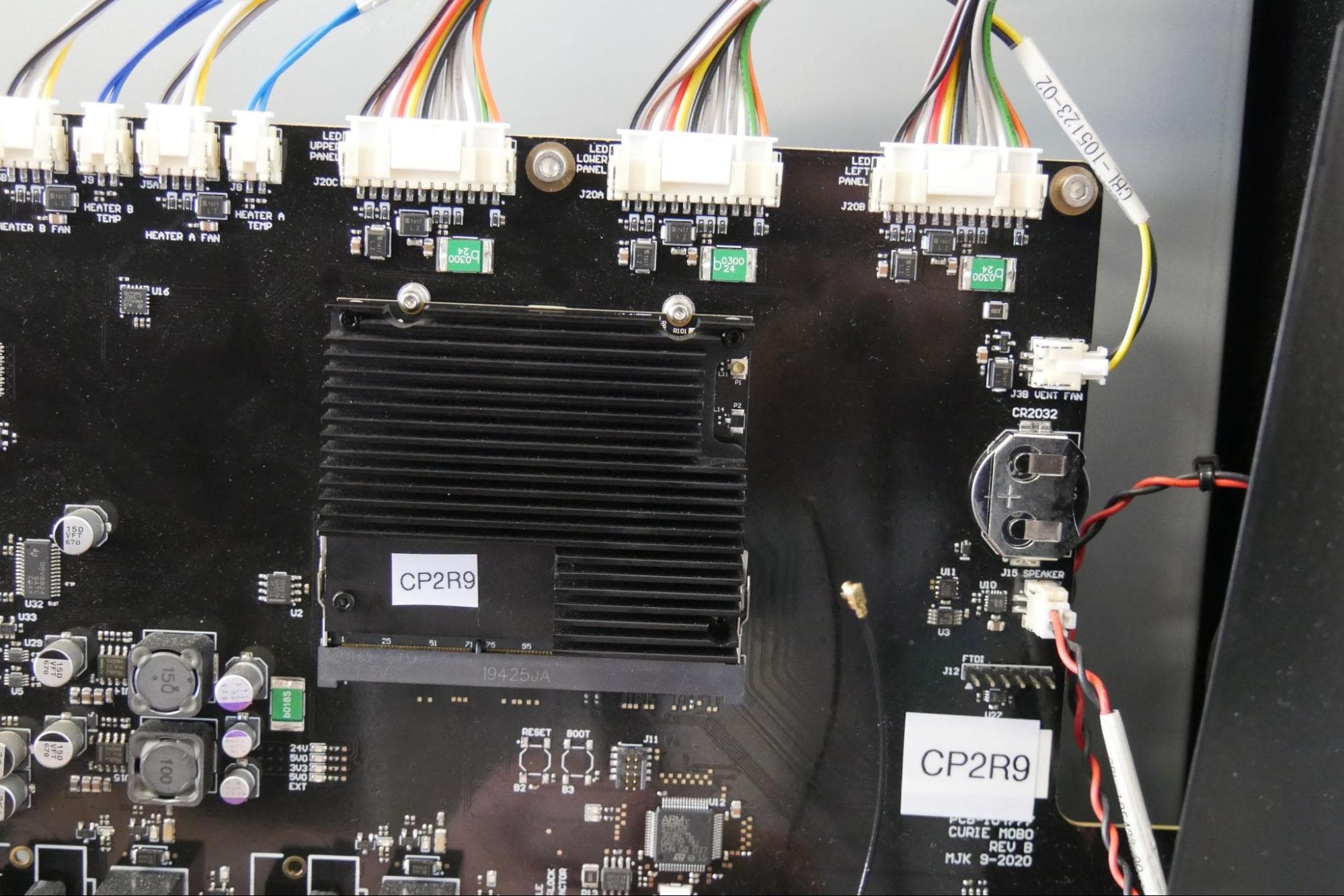
The Wi-Fi antenna is plugged into the SOM at the top- right corner of the board. The connector is accessible through a cutout in the heatsink. Grip the antenna’s connector by its housing and disconnect it from the SOM. Do not pull on the antenna itself.
Removing the SOM
Overview: Unplug and remove the SOM.
Step 1: Unscrew the SOM retention screws
The SOM is plugged into the motherboard and secured with two screws on the top side of the module. Using a 1.3 mm hex driver, loosen and remove two SOM retention screws. Set the screws aside.
Step 2: Unlatch the SOM
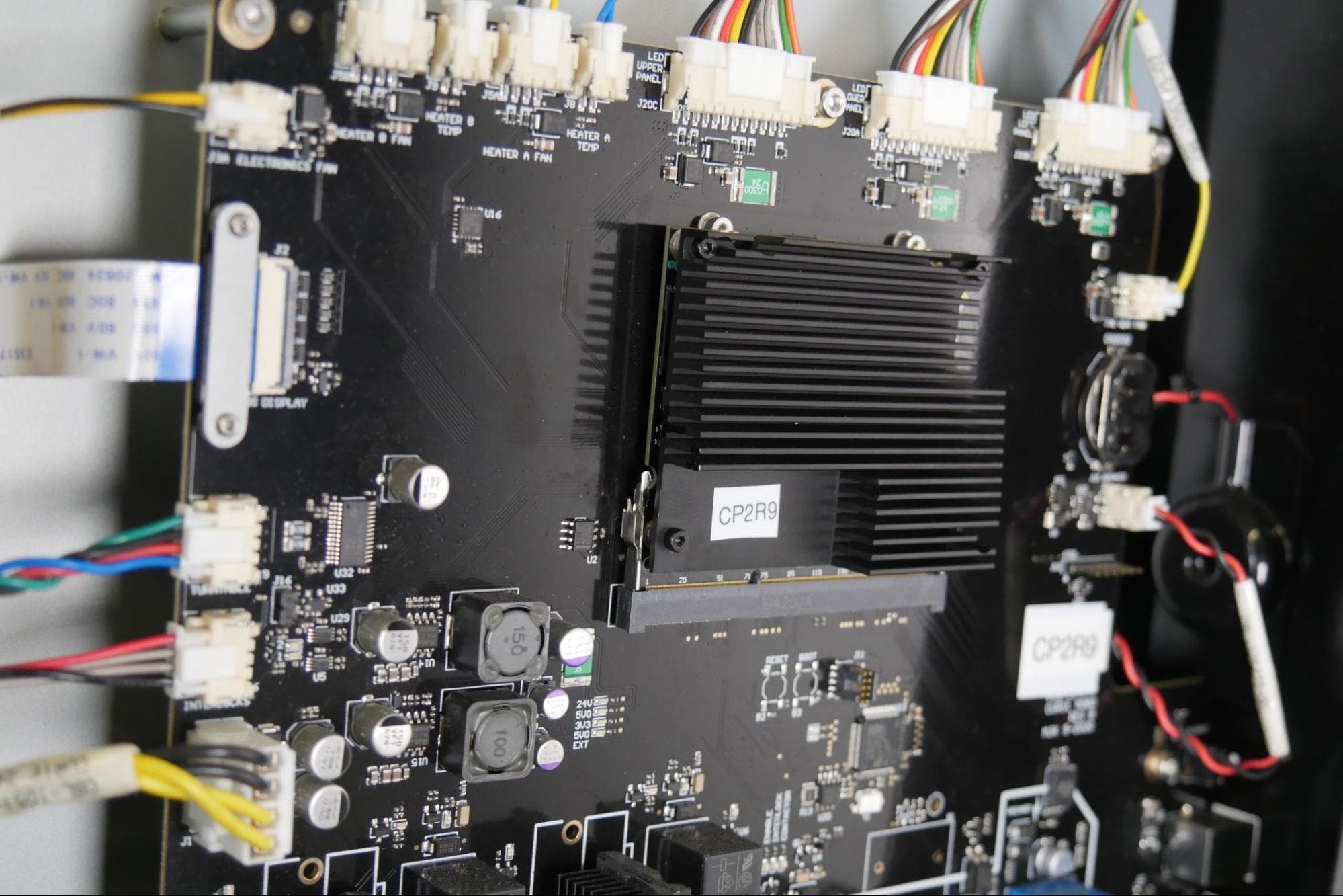
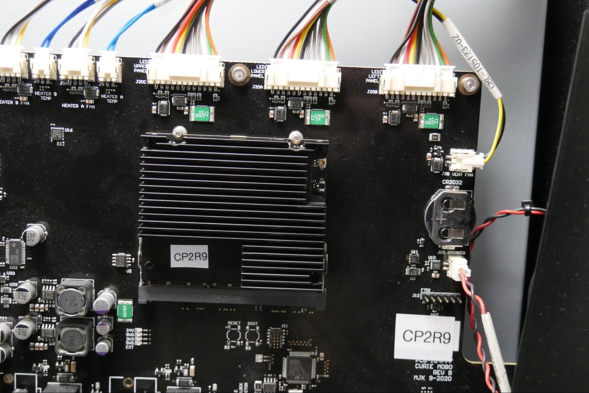
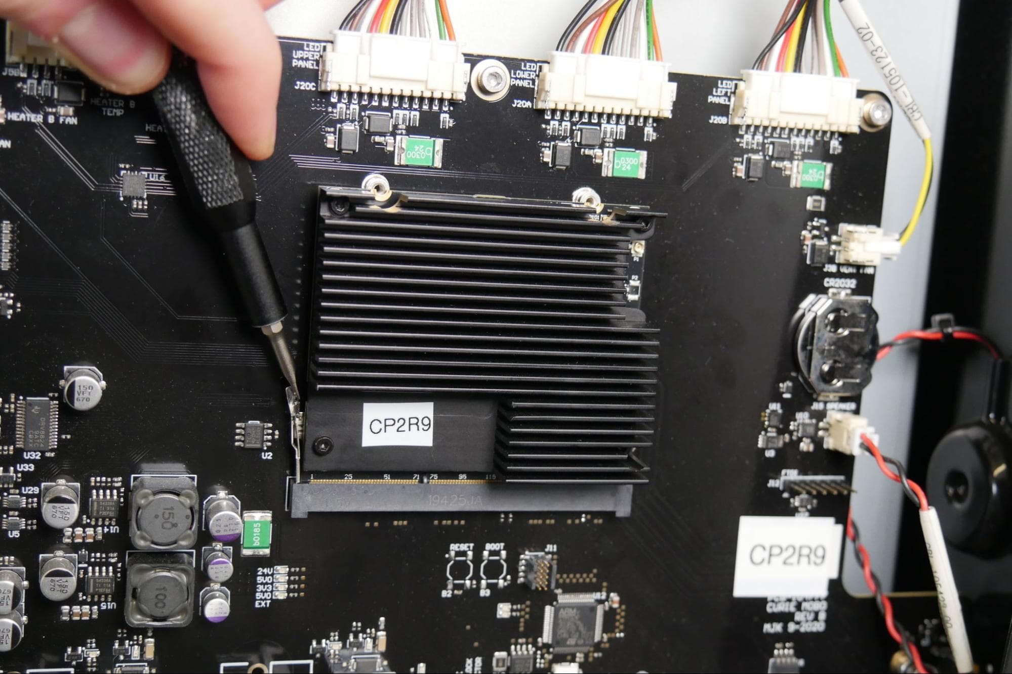
The SOM is additionally secured via two latches: one on the left side of the board and one on the right.
Using fingernails or a small flat-blade screwdriver, open the two latches securing the SOM into its socket. The SOM may tilt forward once you have opened both latches.
Step 3: Remove the SOM
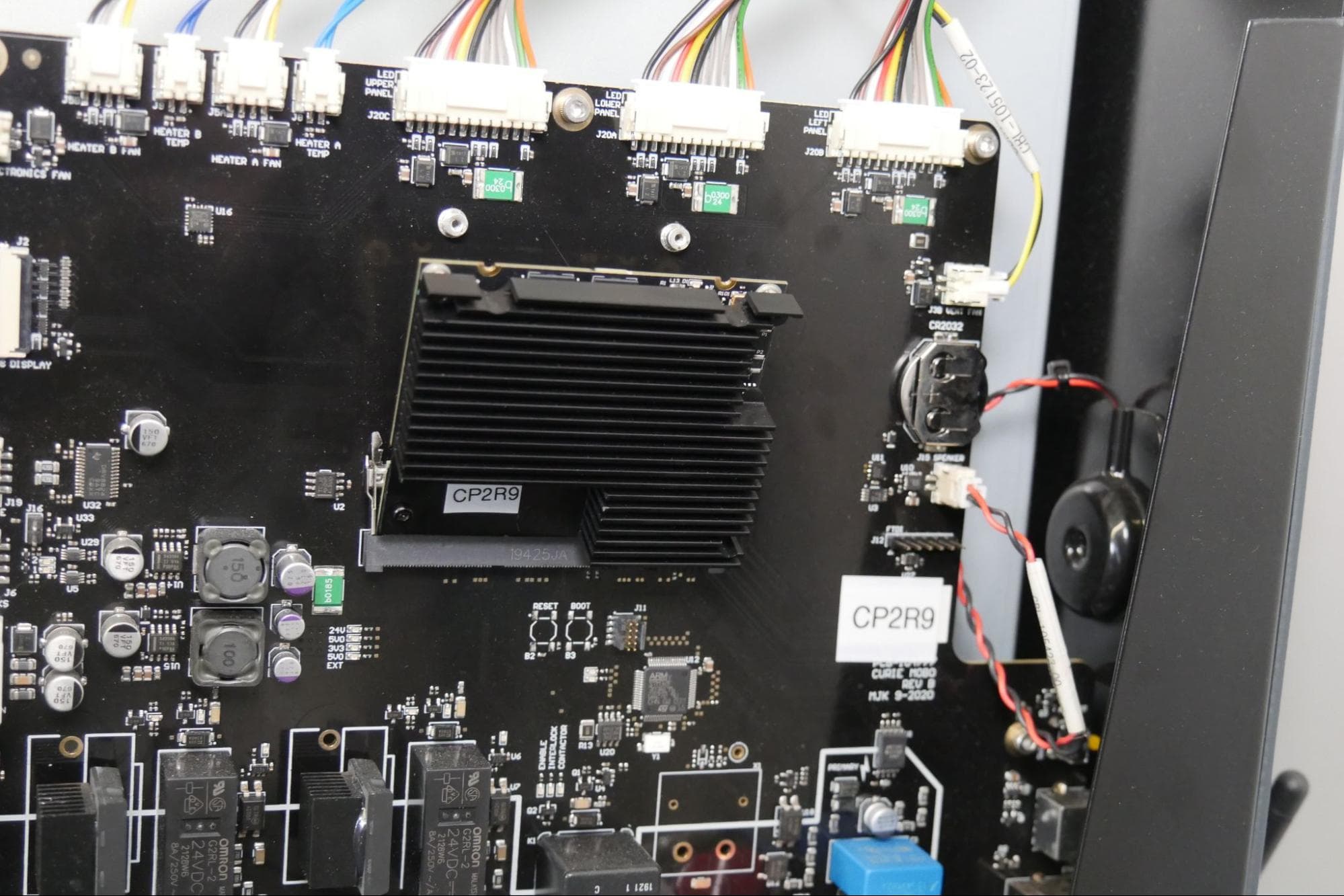
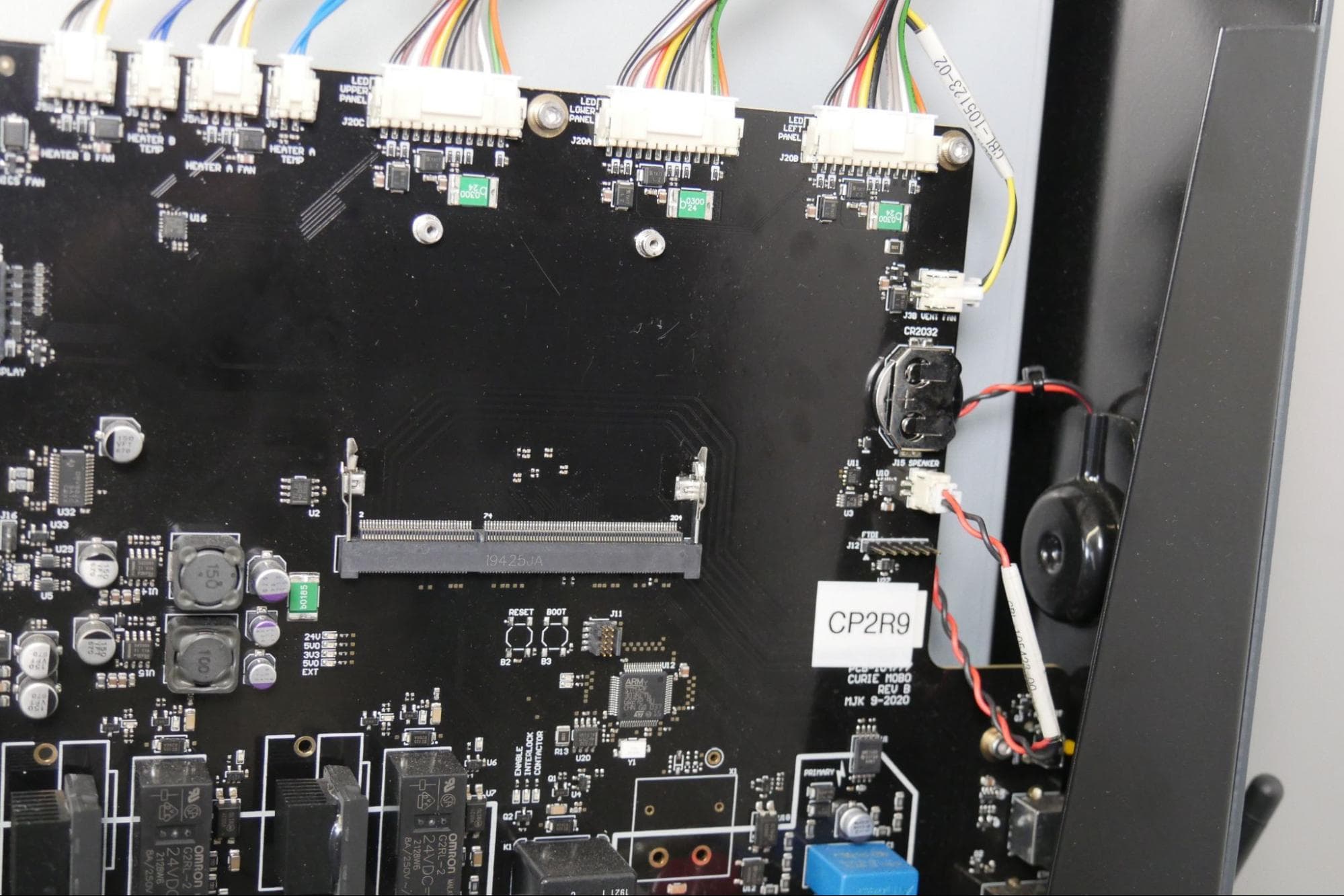
Lift the SOM up from the edge opposite its connector and carefully pull it free from the socket. Place the SOM on a static-free surface.
Installing the replacement SOM
Overview: Install and secure the replacement SOM
Insert the SOM into its socket on the motherboard. Close the two latches. Insert one SOM retention screw into both of the screw holes on the top edge of the SOM. Using a 1.3 mm hex driver, tighten the two screws until finger tight. Do not overtighten.
Step 2: Reconnect the Wi-Fi antenna
The Wi-Fi antenna is plugged into the SOM at the top-right corner of the board. The connector is accessible through a cutout in the heatsink. Align the connector housing on the end of the antenna cable over the socket on the SOM. Using a finger or the tip of a small flat-head screwdriver, push gently to seat the antenna cable.
Reinstalling the top shell
Overview: Reinstall and secure the top shell
Step 1: Reinstall the top shell
Lower the top shell onto the Form Cure L. Make sure you do not pinch any wires between the shell and the frame of the machine. Slide the top shell towards the front of the machine to hook it into place. Check that the screw holes in the top shell line up with the corresponding screw holes in the frame of the machine.
Step 2: Secure the top shell
Thread one 2.5 mm hex screw into each of the six screw holes in the top shell. Using a 2.5 mm hex driver, tighten the screws until finger tight.
Finalizing the procedure
Overview: After replacing the SOM, power on the machine and perform final checks.
Step 1: Power on the machine
Connect the power cable to the Form Cure L and the power supply. The machine initializes. Test the machine to ensure that it operates normally.