
Required supplies:
Formlabs:
- Replacement hopper LED board
Third-party:
- 2.0 mm hex driver (flat-end)
- 2.5 mm hex driver (flat-end)
- 5.5 mm socket driver
- Flat-end screwdriver

On Fuse 1 generation printers, the powder hopper is lit by a set of LEDs at the top of the hopper. A faulty or malfunctioning LED board may make it harder to judge the amount of powder in the hopper.
Use this guide to replace the hopper LED board on a Fuse 1 generation printer.
Required supplies:
Formlabs:
Third-party:
Estimated time: 45–60 minutes, plus time to empty the powder hopper if needed
Danger:
Read and follow all safety instructions and warnings in the operator manual. Replacement with incorrect parts can lead to burns, shock, fire, or explosion. Dispose of all parts in accordance with local regulations.
Warning:
Do not perform this procedure if the printer was printing less than six hours prior. Failure to do so may result in serious burns. Allow the print enclosure to cool to room temperature before touching or inspecting any Fuse 1 components.
Preparing the workspace
Overview: Prepare the printer and a dust-free workspace for replacing the hopper LED board.
Notice:
Fuse 1 generation printers contain sensitive electronic components. Ground yourself before touching any electronics in the printer by using a grounding strap or touching a grounded piece of metal.
Step 1: Prepare the workspace
Clear a workspace around your printer. Ensure that the workspace is well-ventilated and free of dust.
Step 2: Empty the hopper
Insert an empty build chamber. Tap Settings > Calibration > Empty Hopper on the printer’s touchscreen. Follow the on-screen prompt on the Empty Hopper screen to transfer the powder from the hopper to the build chamber. This process may take up to an hour.
Step 3: Clean the hopper
Vacuum the remaining powder out of the hopper. Lay a paper towel at the bottom of the hopper to catch any falling parts.
Step 4: Unplug the printer
Disconnect the power cable before continuing with maintenance. Do not perform maintenance on the printer while it is connected to power. Wait five minutes after disconnecting the printer from power before proceeding.
Danger:
Performing maintenance on the printer while it is plugged in increases the risk of electric shock. Never remove the back panel of the printer while the printer is plugged in. Never reconnect the printer to power while the back panel is uninstalled.
Removing the top panel
Overview: Remove the top panel to access the interior of the printer.
Step 1: Remove the top panel screws
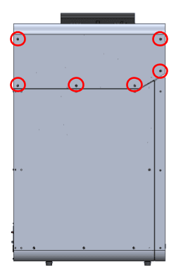
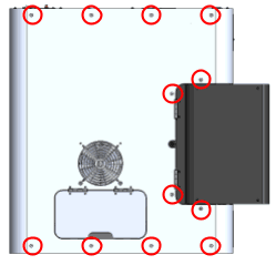
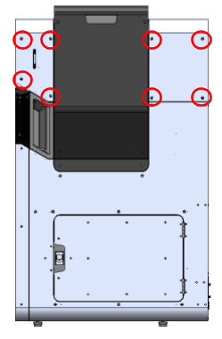
Using a 2.5 mm hex driver, remove the 26 6 mm M4 countersunk screws securing the top panel to the printer:
Removing the hopper-side panel and hopper shell
Overview: Remove paneling on the hopper side of the printer to access the LED board.
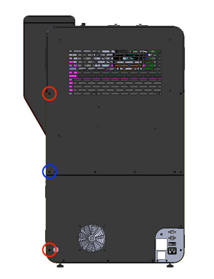
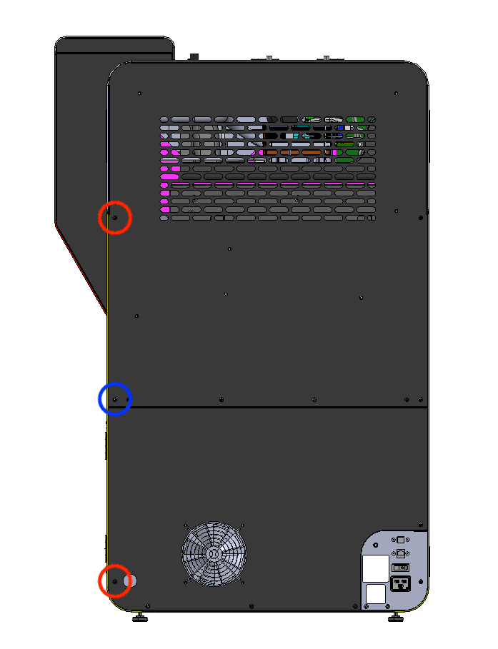
Using a 2.5 mm hex driver, loosen and remove the two black (circled in red) and one chrome (circled in blue) 8.0 mm M4 button head screws from the back-left of the printer. Take note of the locations of these screws, as the placement of the chrome screws is critical to the printer's electrical grounding. Set the screws aside.
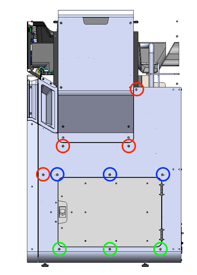
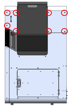
Move to the hopper side of the printer. Using a 2.5 mm hex driver, loosen and remove the 10 M4 countersunk screws holding the hopper-side panel to the printer. Remove the top-most 6.0 mm countersunk screws last to make removing the panel easier. Set the screws aside.
Allow the panel to tilt away from the printer, allowing access to the interlock switch cables. Do not remove the panel at this time.
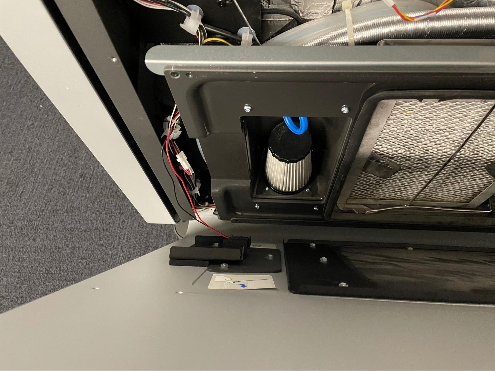
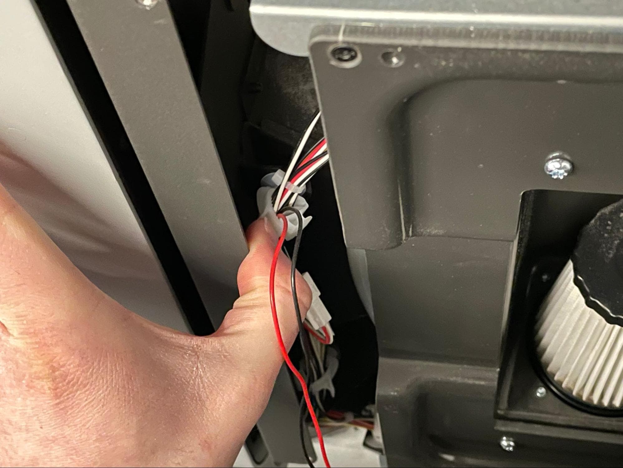
Locate the black and red cables leading to the interlock switch on the inner left-hand side of the panel. The cables are retained by a cable clamp. Unlock the cable clamp and disconnect the cable labeled C033.
Separate the hopper-side panel from the printer, taking care to ensure that none of the cables are caught or tangled. Set the panel down on a flat, clean surface.
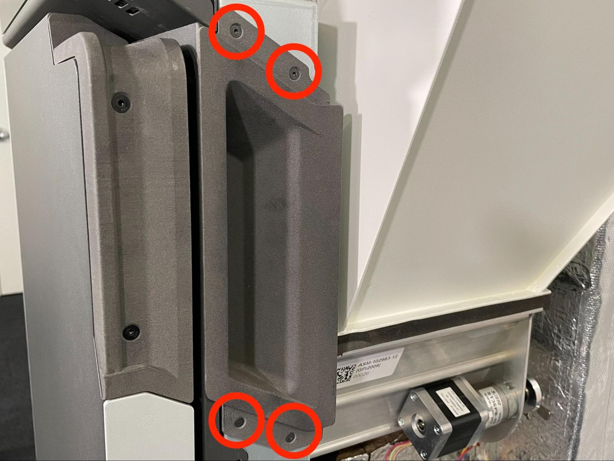
Using a 2.0 mm hex driver, loosen and remove the four 10.0 mm M3 black countersunk screws holding the inner door handle to the printer. Remove the door handle and set it and the screws aside.
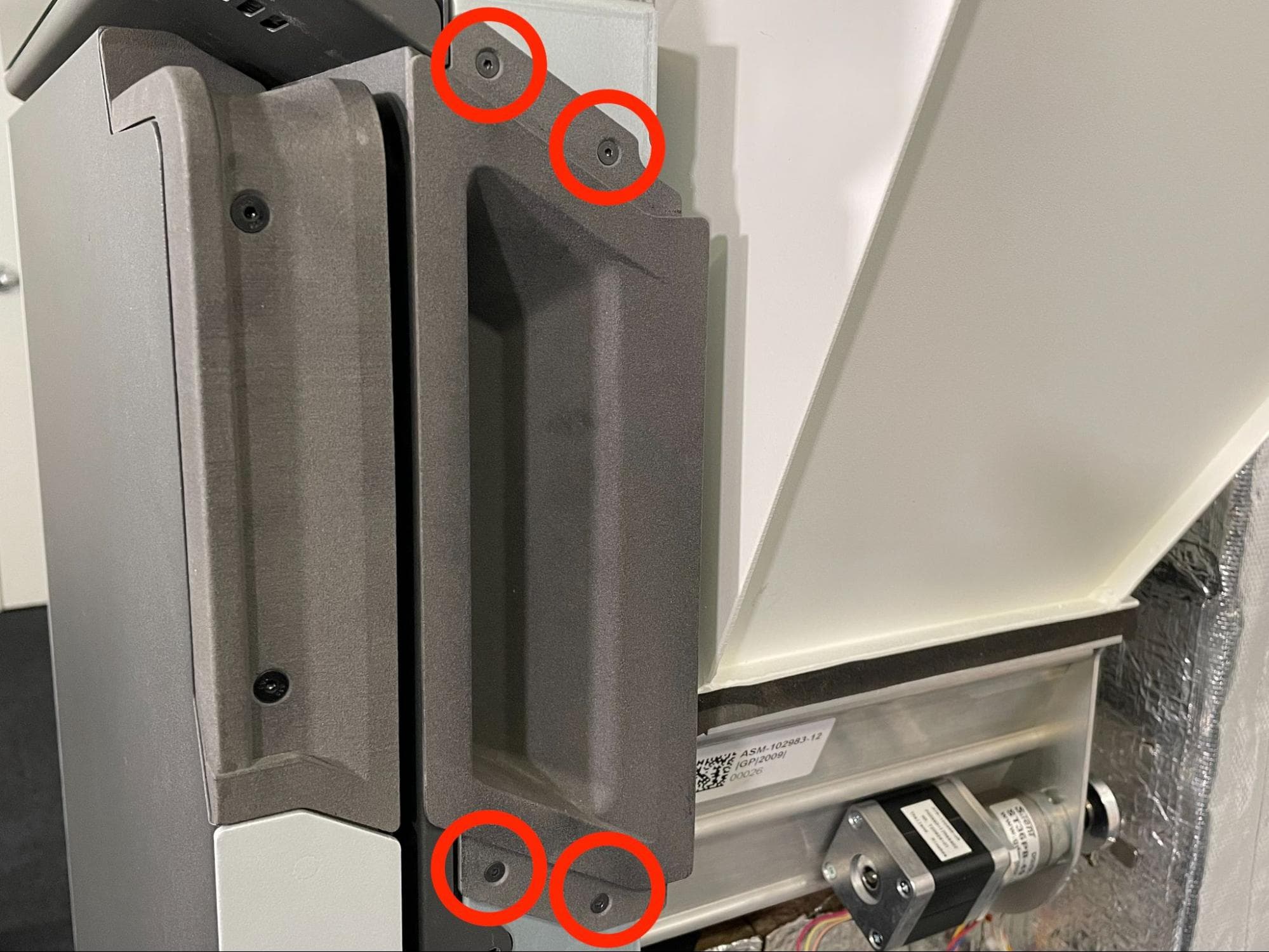
Step 6: Remove the hopper shell
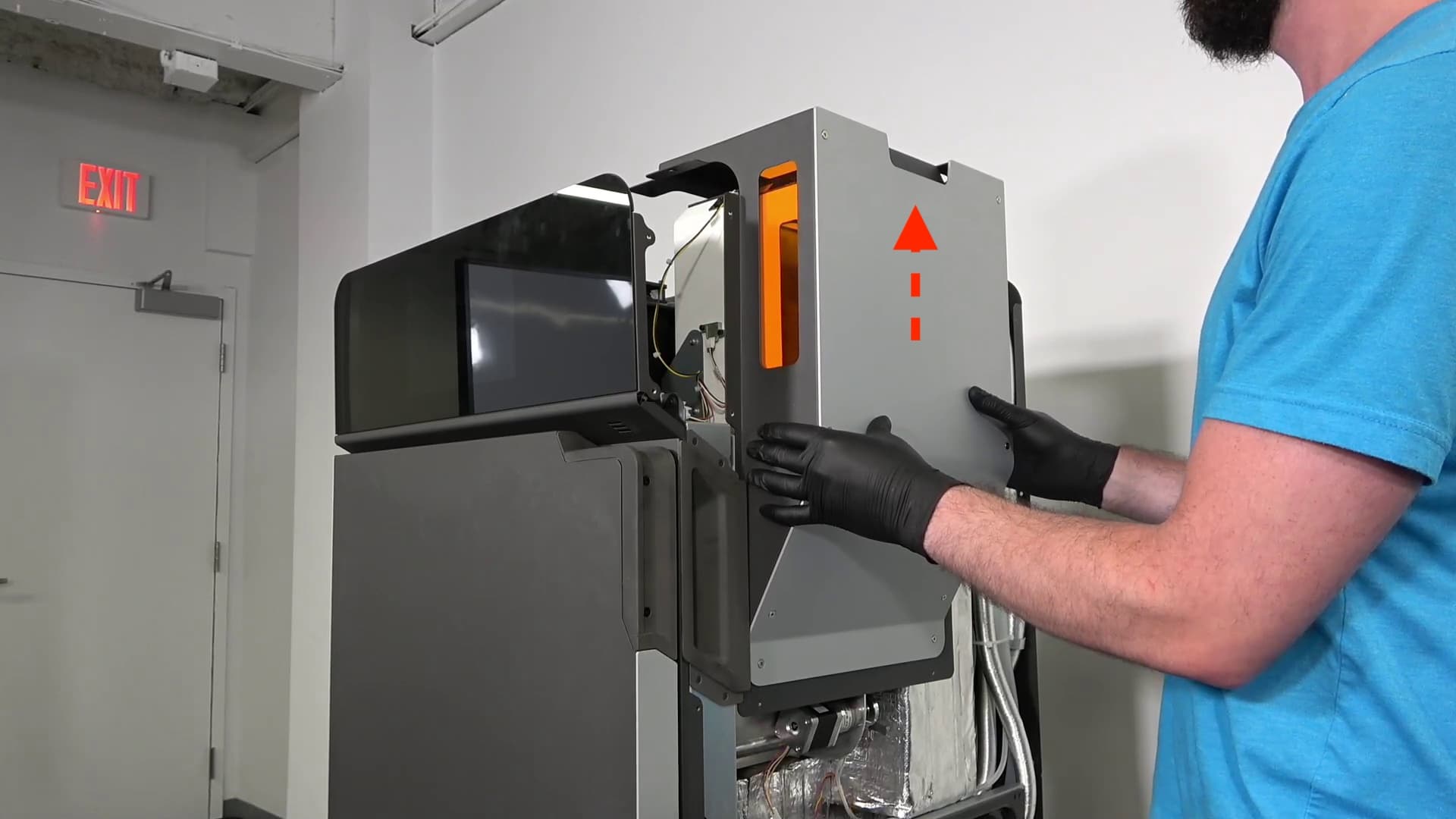
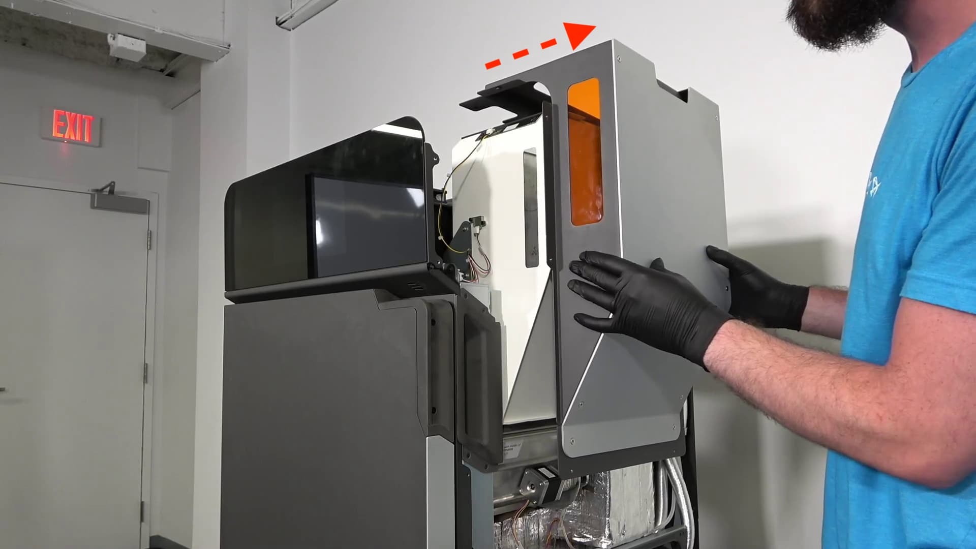
Grip the sides of the hopper shell. Carefully lift the shell upwards then pull it away from the printer. Set the hopper shell and lid aside.
Removing the original hopper LED board
Overview: Disconnect and remove the original hopper LED board
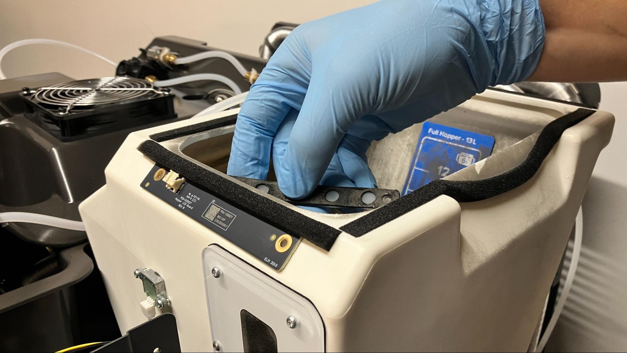
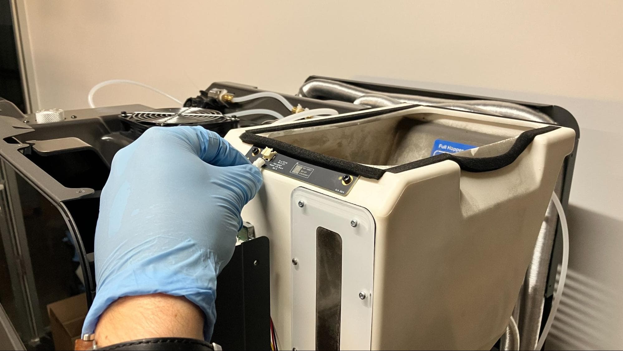
Locate the LED board, positioned at the front of the hopper along its top edge. Disconnect the JST connector labeled C048 from the board.
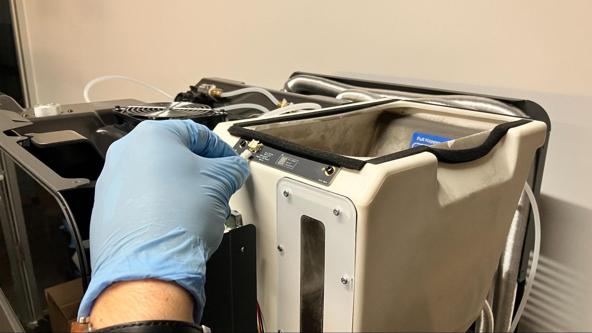
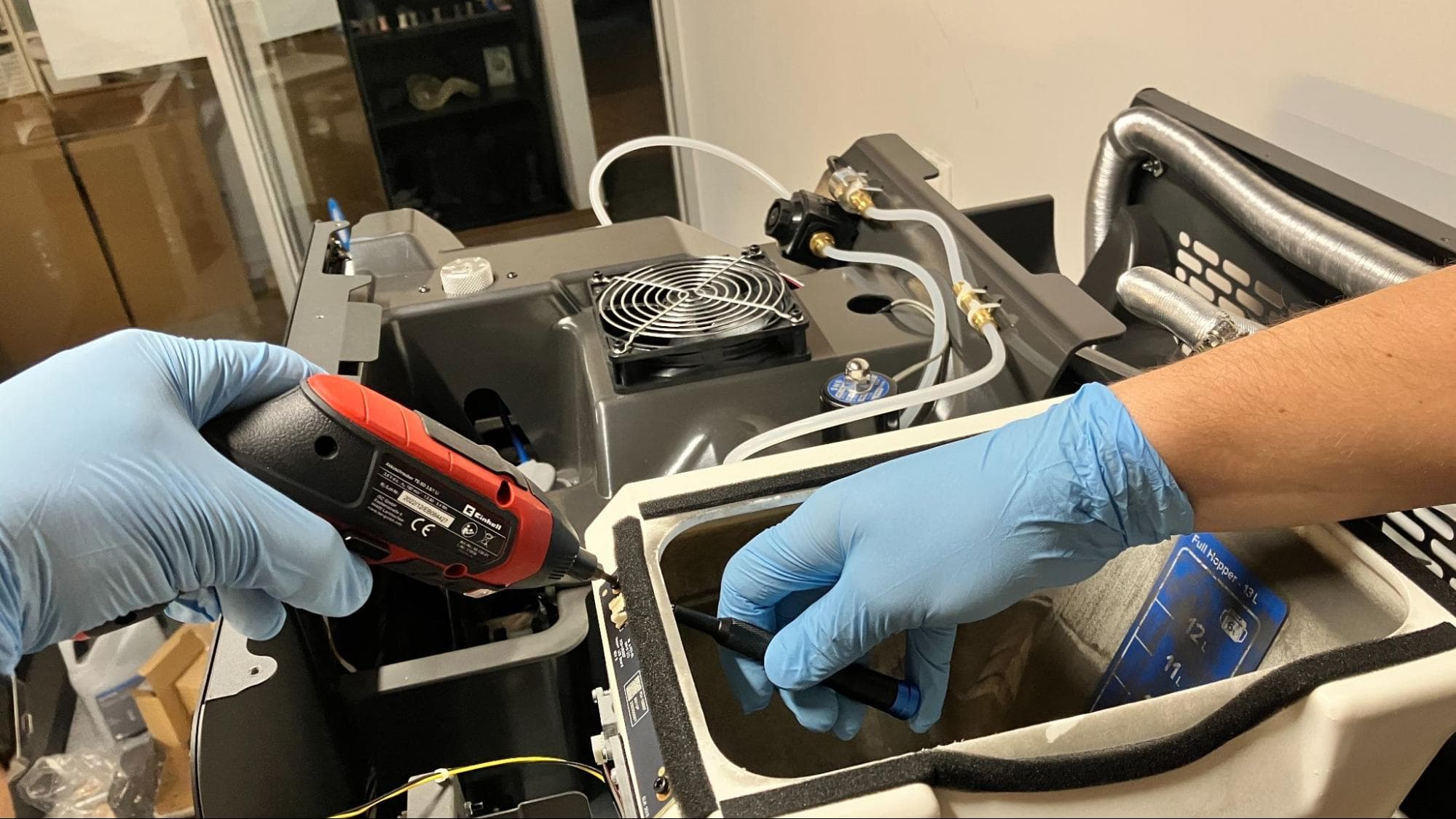
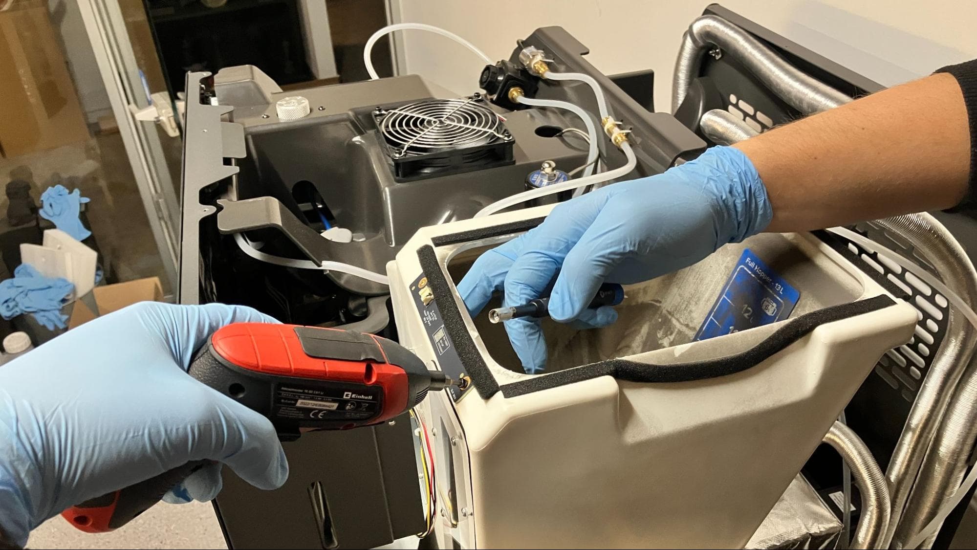
The hopper LED board is secured using two screws, each with a corresponding nut on the inside of the hopper lip. Use a 5.5 mm socket to hold one of the nuts in place, then unscrew the corresponding screw with a flat-end screwdrive. Take care not to let the nut fall into the hopper. Repeat with the other screw and nut, then set the screws and nuts aside.
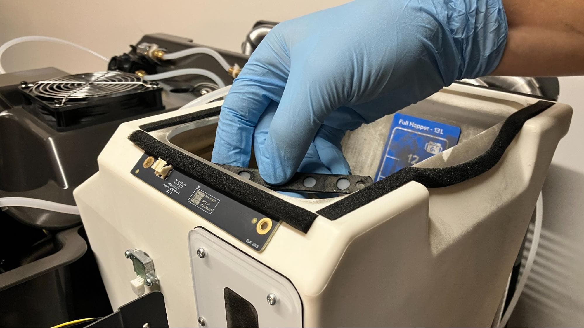
Remove the hopper LED board diffuser from under the hopper lip. Be careful not to drop the part into the hopper.
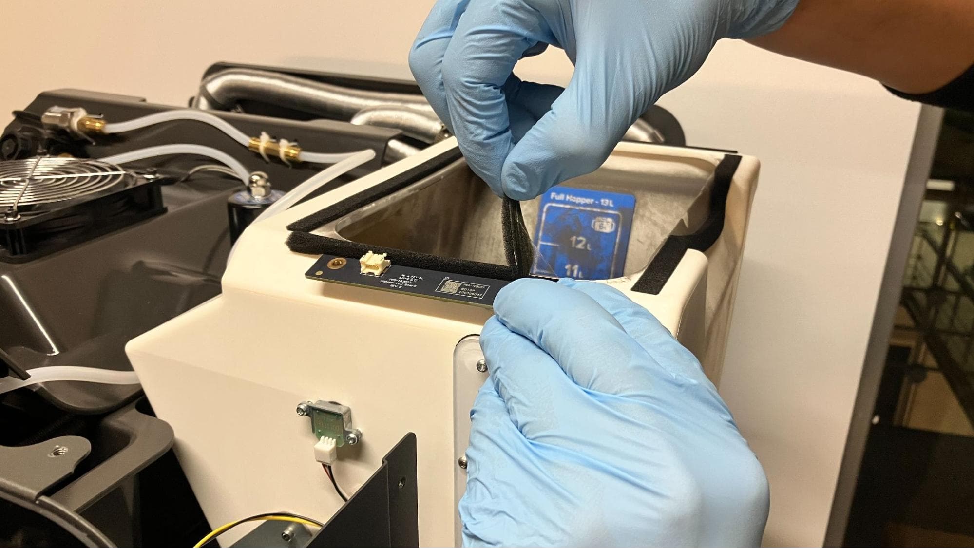
Carefully peel off the protective foam seal holding the LED board to the edge of the hopper. Set the foam aside for reuse. Remove the hopper LED board and set it aside for disposal with electronic waste.
Installing the replacement hopper LED board
Overview: Mount, secure, and connect the replacement hopper LED board.
Place the new hopper LED board on its mounting surface with the cable connector oriented to the left. Reapply the protective foam seal across the top edge of the board.
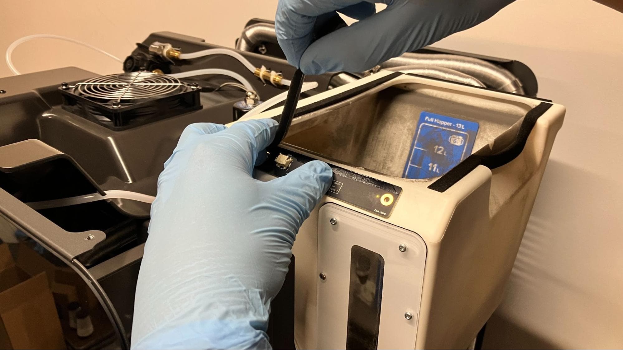
Hold the diffuser in place under the hopper lip, opposite the LED board. Insert a 2.5 mm hex screw into one of the screw holes and secure it with a nut. Repeat with the other screw and nut.
Connect the cable labeled C048 to the hopper LED board.
Reinstalling the hopper shell and hopper-side panel
Overview: After installing the new hopper LED board, reinstall the paneling on the hopper side of the printer.
Align the four screw holes in the inner door handle with the corresponding screw holes on the front edge of the hopper side of the printer. Thread one 10.0 mm M3 black countersunk screw into each of the four screw holes, then use a 2.0 mm hex driver to tighten until snug.
Step 2: Mount the hopper shell
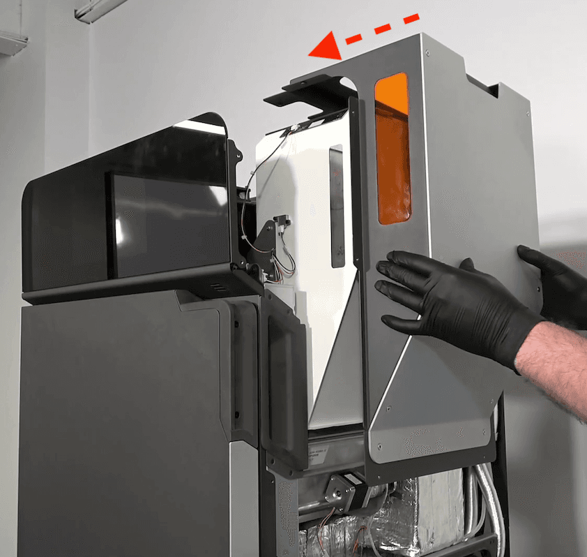
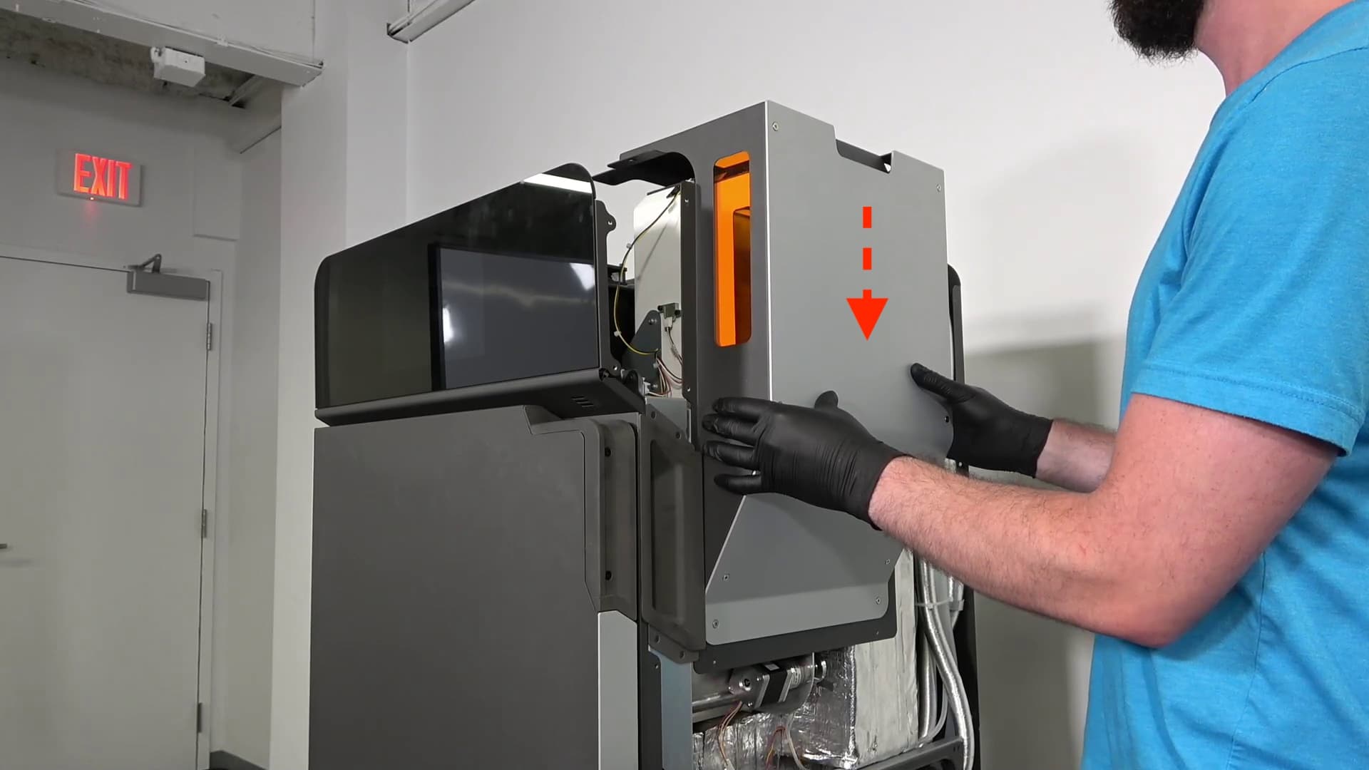
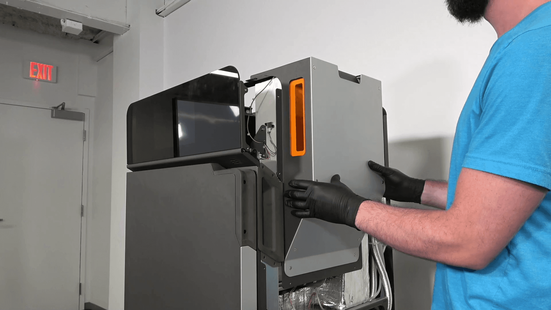
Grab the sides of the hopper shell and bring it towards the printer. Align the shell with the hopper body, then slide it down on top of the hopper.
Step 3: Reconnect the interlock switch cable
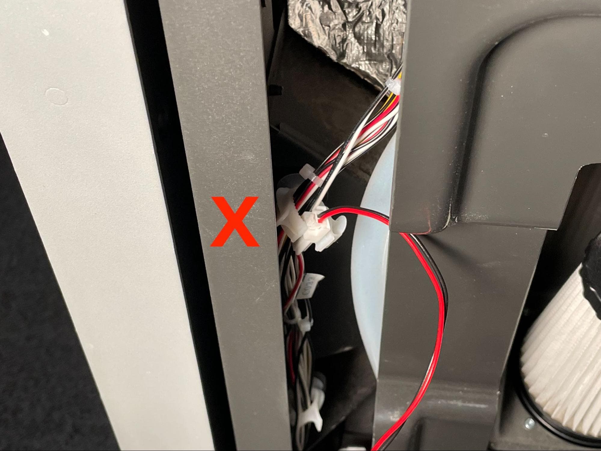
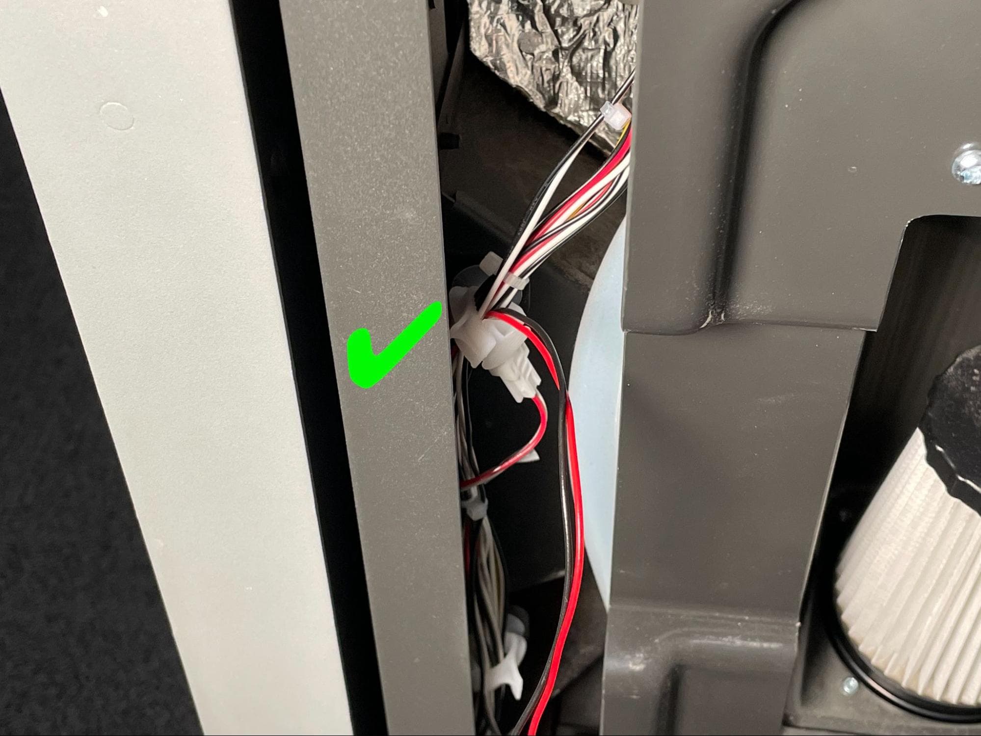
Align the bottom of the hopper-side panel to the bottom of the printer and allow it to lean against you. Reconnect the interlock switch cable, labeled C033, to its receptacle. Route the cables into the cable clamp with the connector positioned below the clamp. If necessary, tuck the interlock cable slack into the side of the printer’s frame.
Thread one M4 countersunk screw into each of the 10 screw holes in the hopper-side panel. Using a 2.5 mm hex driver, tighten until snug. For greatest convenience and ease of installation, thread and tighten in the following order:
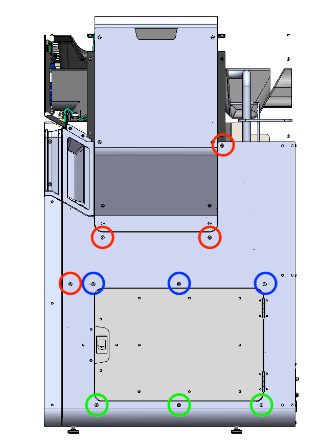
Thread the two black 8.0 mm M4 button head screws into the screw holes circled in red in the image here. Thread the chrome 8.0 mm M4 button head screw into the screw hole circle in blue here. Using a 2.5 mm hex driver, tighten until snug.
Reinstalling the top panel
Overview: After installing the new hopper LED board, reinstall and secure the top panel.
Step 1: Align the top panel
Lift the top panel and place it on top of the printer. Align the screw holes in the top panel with the corresponding holes in the printer frame.
Step 2: Secure the top panel screws
Thread a 6 mm M4 countersunk screw into each of the 18 marked screw holes in the top panel:
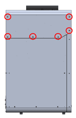
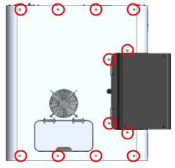
Using a 2.5 mm hex driver, tighten the screws until snug.
Finalizing the repair
Overview: After installing the replacement hopper LED board, power on the printer and perform final checks.
Step 1: Power on the printer
Connect the power cable to the printer and the power supply. The printer initializes. Check that the hopper LEDs light up. Contact Formlabs Support or your certified service provider to share the results of the procedure.