
Required supplies:
Formlabs:
- Replacement power supply (RP-FS1-PSU-01)
Third-party:
- 2.5 mm hex driver (flat-end)
- #2 Phillips screwdriver
- Telescoping magnet wand
- Antistatic wrist band

The power supply on Fuse 1 and Fuse 1+ 30W printers is located behind the rear panel. A broken or malfunctioning power supply prevents the printer from functioning.
Use this guide to replace the power supply on a Fuse 1 generation printer.
Required supplies:
Formlabs:
Third-party:
Estimated time: 15–30 minutes
Danger:
Read and follow all safety instructions and warnings in the operator manual. Replacement with incorrect parts can lead to burns, shock, fire, or explosion. Dispose of all parts in accordance with local regulations.
Preparing the workspace
Overview: Prepare the printer and a dust-free workspace for replacing the power supply.
Notice:
Fuse 1 generation printers contain sensitive electronic components. Ground yourself before touching any electronics in the printer by using a grounding strap or touching a grounded piece of metal.
Step 1: Prepare the workspace
Clear a workspace around your printer. Ensure that the workspace is well-ventilated and free of dust.
Step 2: Unplug the printer
Disconnect the power cable before continuing with maintenance. Do not perform maintenance on the printer while it is connected to power. Wait five minutes after disconnecting the printer from power before proceeding.
Danger:
Performing maintenance on the printer while it is plugged in increases the risk of electric shock. Never remove the back panel of the printer while the printer is plugged in. Never reconnect the printer to power while the back panel is uninstalled.
Step 3: Remove the Wi-Fi antenna
Unscrew and remove the Wi-Fi antenna, if it is connected.
Removing the lower rear panel
Overview: Remove the lower rear panel to access the interior of the printer.
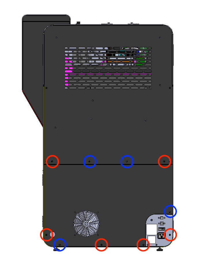
The six black lower rear panel screws are circled in red. The four chrome lower rear panel grounding screws are circled in blue.
Using a 2.5 mm hex driver, remove the six black panel screws and the four chrome panel grounding screws securing the lower rear panel to the printer. Set the screws aside, taking care to separate the black and chrome screws for later reinstallation.
Pull the lower rear panel straight back and away from the printer. Lay it down on a flat, clean surface.
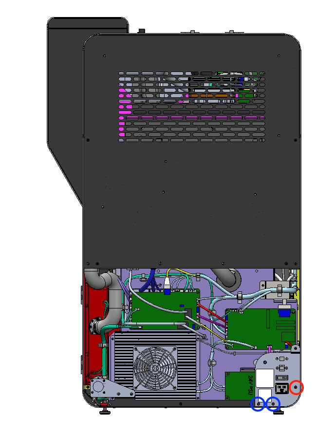
Using a 2.5 mm hex driver, remove the one black and two chrome 8 mm M4 button screws securing the I/O bulkhead panel to the printer.
To avoid damaging the Wi-Fi coaxial cable, do not pull the I/O bulkhead panel away from the printer.
Removing the original power supply
Overview: Unplug and remove the original power supply from the printer.
Step 1: Prepare to uninstall the power supply
Put on an antistatic wrist band, then connect it to a known ground point.
NOTICE:
Do not connect the wrist band any surfaces that are powder-coated or painted.
Step 2: Remove the power supply cover (Fuse 1+ 30W only)
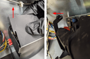
On Fuse 1+ 30W printers, the power supply is shrouded by a plastic cover. The cover is held together with snap features, which come apart by gently flexing the plastic and pulling the tabs free. Remove the plastic cover from the power supply by first pulling up on the top corners, then separating all four sides from the metal standoffs.
Step 3: Disconnect the power supply cables
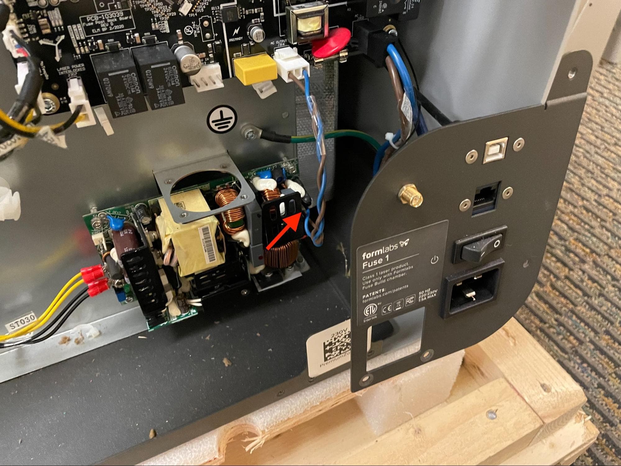
Disconnect the blue and brown cable from the power supply.
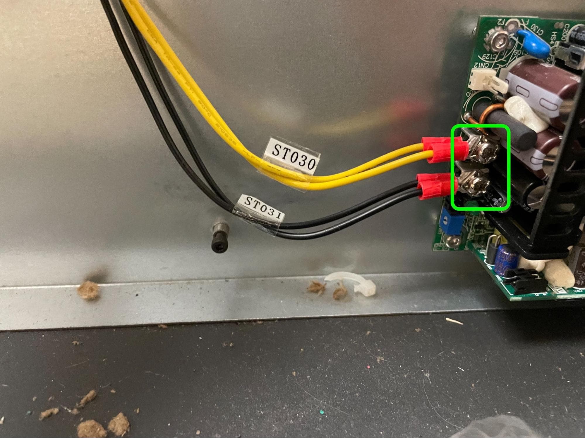
Use a #2 Phillips screwdriver to partially loosen the two terminal screws securing the wires labeled ST030 and ST031 to the power supply. Separate the wires from the terminals.
Tip:
Stop loosening the terminal screws once the wires are free so that the screws do not get lost.
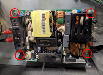
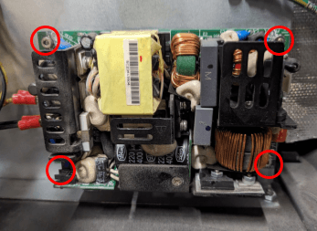
Using a 2.5 mm hex driver, remove the four 10 mm M3 socket head screws securing the power supply to the printer. Set the screws aside. Remove the power supply from the printer and set it aside for disposal.
Installing the replacement power supply
Overview: Mount, secure, and connect the replacement power supply.
Step 1: Prepare to install the power supply
If you have not already, put on an antistatic wrist band and connect it to a known ground point. Remove the new power supply from its packaging.
Notice:
Do not connect the wrist band to any surfaces that are powder-coated or painted.
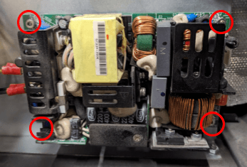
Orient the power supply with the screw terminals on the left. Align the screw holes in the power supply with the four standoffs at the back of the printer. Thread one 10 mm M3 socket screw into each of the four screw holes. Using a 2.5 mm hex driver, tighten the screws until snug.
Step 3: Connect the yellow wires to the top screw terminal
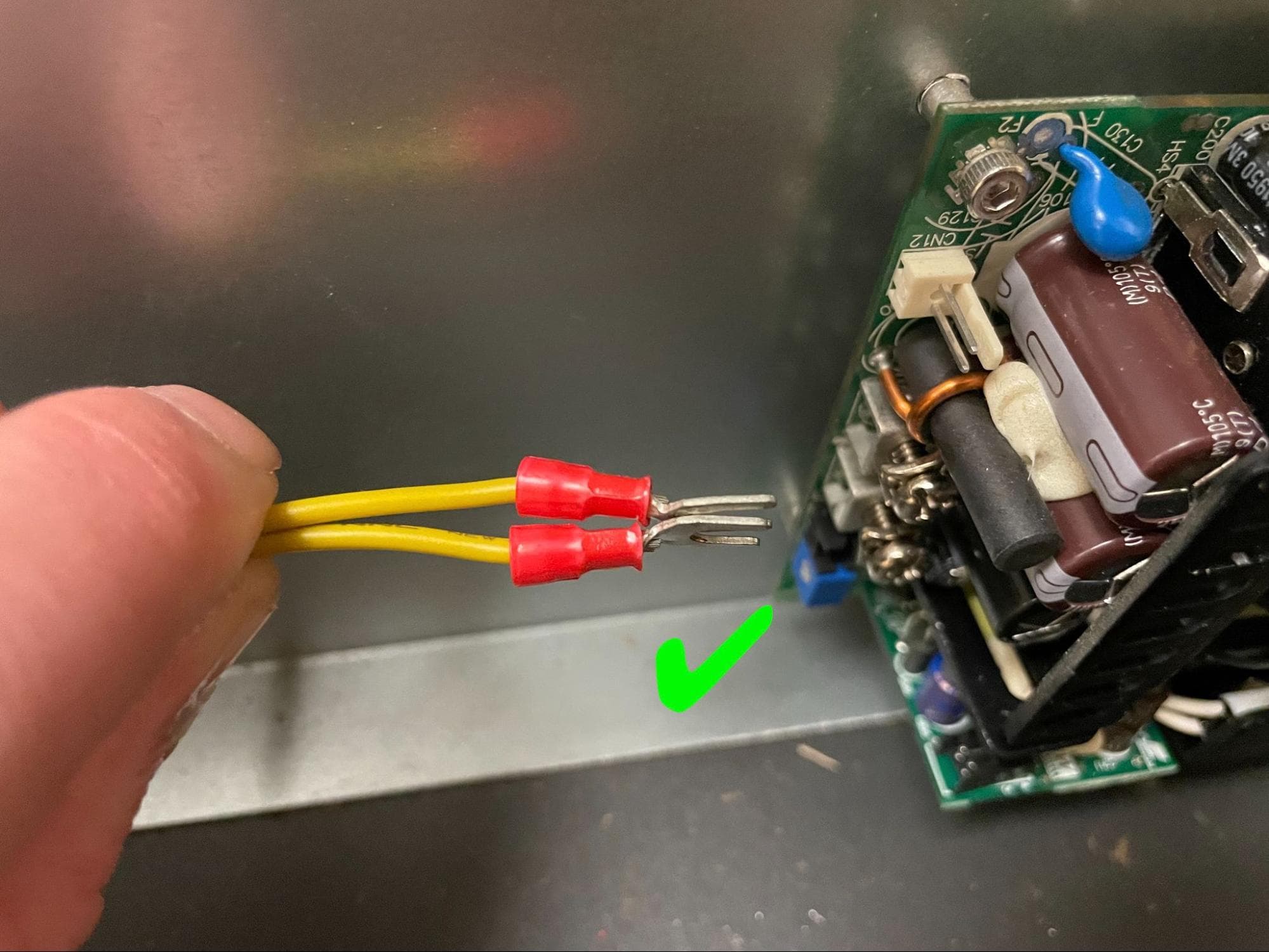
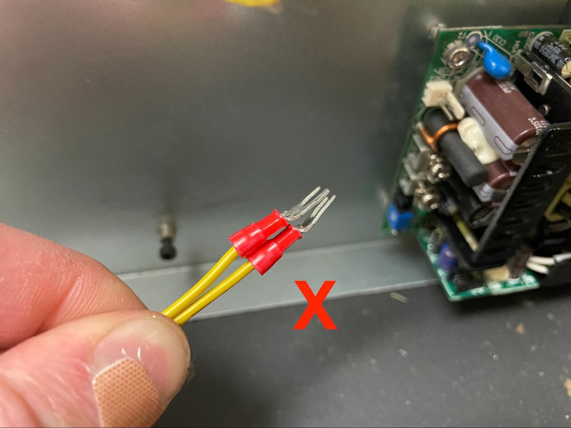
Insert the two yellow wires labeled ST030 into the top screw terminal, with the spade connectors facing back-to-back. Keep the square nut between the terminal screw head and the spade connectors.
Use a #2 Phillips screwdriver to tighten the terminal screw and secure the spade connectors.
Insert the two black wires labeled ST031 into the bottom screw terminal, with the spade connectors facing back-to-back. Keep the square nut between the terminal screw head and the spade connectors.
Use a #2 Phillips screwdriver to tighten the terminal screw and secure the spade connectors.
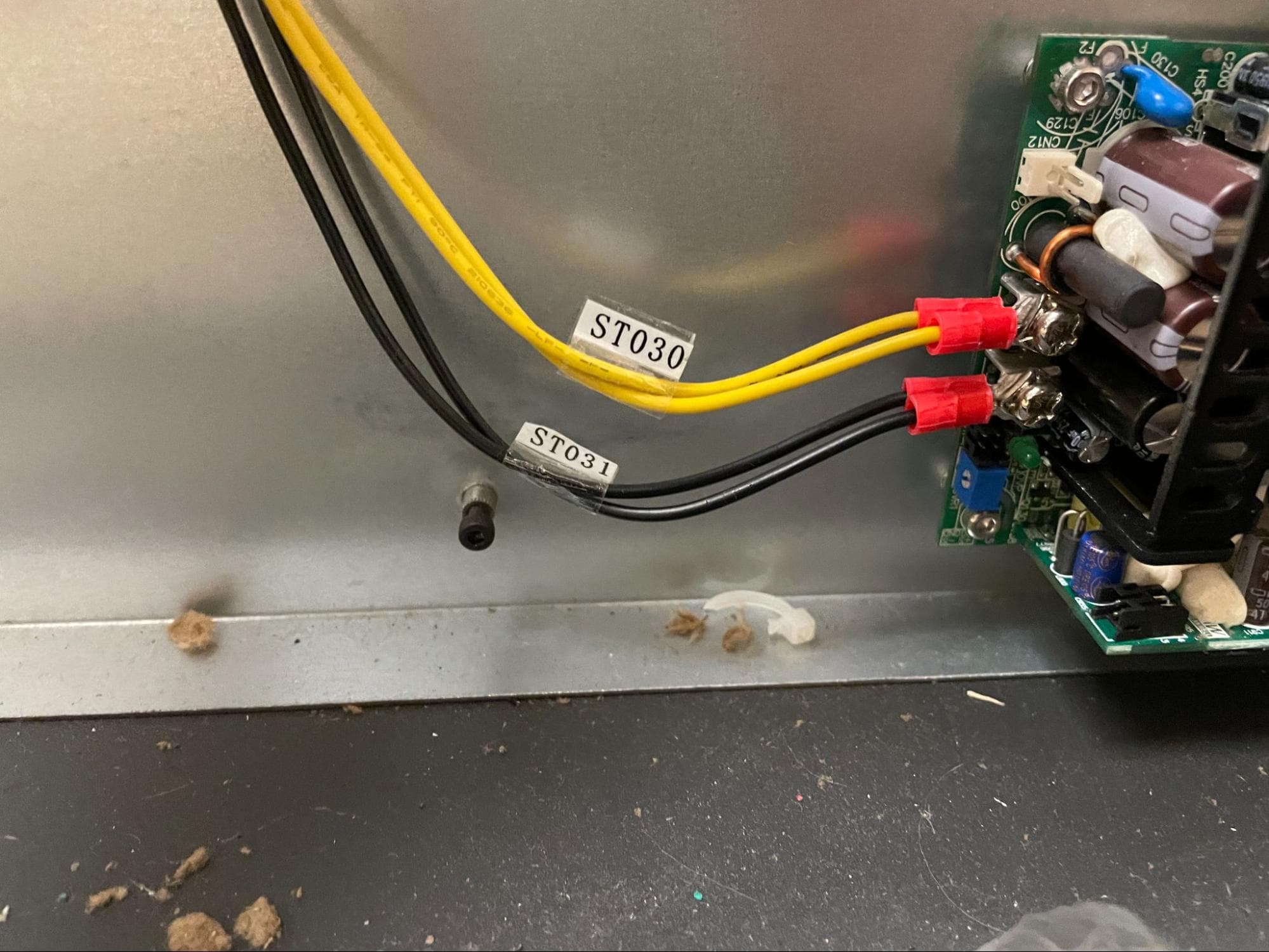
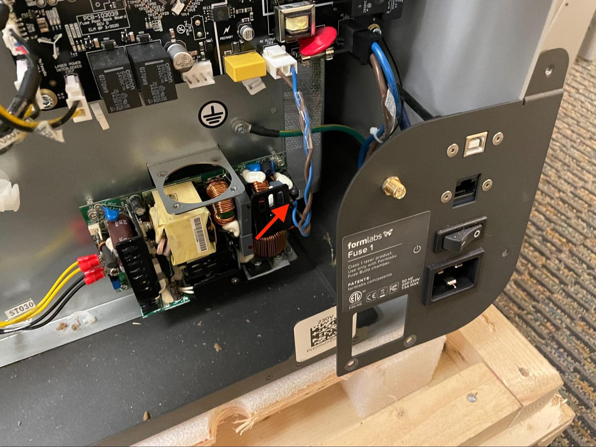
Connect the blue and brown cable to the power supply.
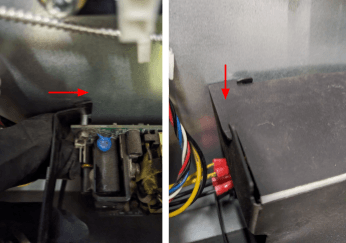
Reinstall the plastic power supply cover by first pushing the four sides onto the metal standoffs, then by pushing the top corners into place.
Reinstalling the lower rear panel
Overview: After installing the replacement power supply, reinstall and secure the lower rear panel.
Lift the I/O bulkhead panel and align the three screw holes with the corresponding screw holes in the printer frame. Thread one black 6 mm M4 button head screw into the screw hole on the right of the panel. Thread two chrome 6 mm M4 button head screws into the screw holes on the bottom of the panel. Using a 2.5 mm hex driver, tighten the screws until snug.
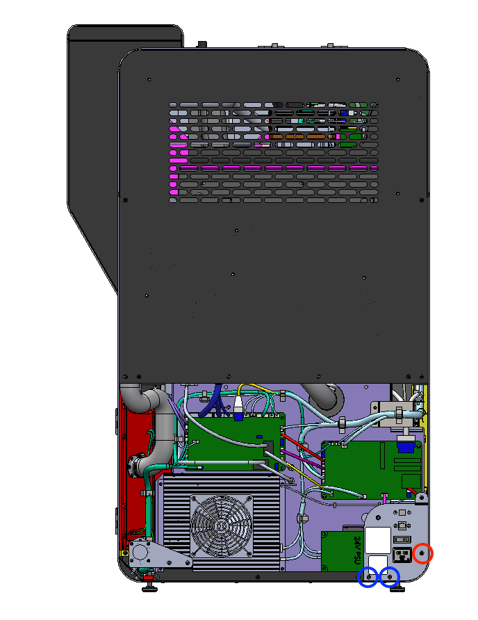
The six black lower rear panel screws are circled in red. The four chrome lower rear panel grounding screws are circled in blue.
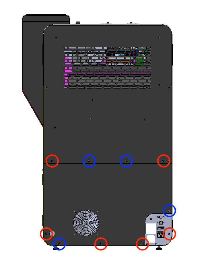
Thread the panel screws into the indicated screw holes on the lower rear panel. Refer to the image for the correct locations of the black and chrome screws. Using a 2.5 mm hex driver, screw in the six black panel screws and four chrome panel grounding screws securing the lower rear panel to the printer.
Notice:
The placement of the chrome screws is critical to the printer's electrical grounding. Incorrect placement may lead to printer damage.
Step 3: Reinstall the Wi-Fi antenna (optional)
Screw the Wi-Fi antenna onto the jack on the back of the unit.
Finalizing the repair
Overview: After installing the replacement power supply, power on the printer and perform final checks.
Step 1: Power on the printer
Connect the power cable to the printer and the power supply. The printer initializes.
Step 2: Test the repair
Start a print. Monitor the printer to ensure that the print proceeds normally. Contact Formlabs Support or your certified service provider to share the results of the procedure.