WHITE PAPER
Formlabs Logo

Replacing the Fuse Sift motherboard

Replacing the Fuse Sift motherboard

The motherboard is the main electronics module on the Fuse Sift that controls various subsystems. The motherboard is located in an enclosure at the back of the machine. A malfunctioning motherboard may prevent the printer from printing properly.

Use this guide to replace the Fuse Sift motherboard.

Notice:

This procedure applies exclusively to Fuse Sift units manufactured after June 22nd, 2021 running Fuse Sift firmware version 1.4.3 or later prior to replacing the motherboard. A Fuse Sift is ineligible for motherboard replacement if it was manufactured before June 22nd, 2021 or is unable to successfully update its firmware to version 1.4.3 or later. If a firmware version older than 1.4.3 is installed when the motherboard is replaced, the Fuse Sift will display an error message stating that the new motherboard's signature is unrecognized.
Fuse Sift motherboard

Required supplies:

Formlabs:

Third-party:

  • 1.3 mm hex driver (flat-end)
  • 2.5 mm hex driver (flat-end)
  • #2 Phillips screwdriver
  • ESD-safe spudger (recommended) or ESD-safe tweezers
  • Antistatic wristband
  • Appropriate personal protective equipment for the powder in use, as defined in the safety data sheet (SDS)
  • Loctite 243 or equivalent threadlocker
  • Computer with PreForm
  • WAN internet connection
  • USB A to B cable

Estimated time: 30–45 minutes

Preparing the machine

Overview: Before replacing the Fuse Sift motherboard, check its firmware version and update if needed.

Step 1: Check the firmware version

On the Fuse Sift touchscreen, tap Settings > System > Firmware Version.

Step 2: Update firmware

If the version installed is older than version 1.4.3, update the firmware to the latest version available prior to replacing the motherboard.

Removing the rear enclosure panel

Overview: Remove the rear enclosure panel to better access the cartridge drawer components.

Step 1: Unplug the Fuse Sift

Power off the Fuse Sift, then unplug the power cable from the rear panel.

Danger:

Performing this procedure on the Fuse Sift while it is plugged in increases the risk of electric shock. After disconnecting the power from the Fuse Sift, wait at least five minutes before servicing.

Step 2: Unscrew the Wi-Fi antenna

Remove the Wi-Fi antenna, if present.

Step 3: Remove the rear enclosure panel

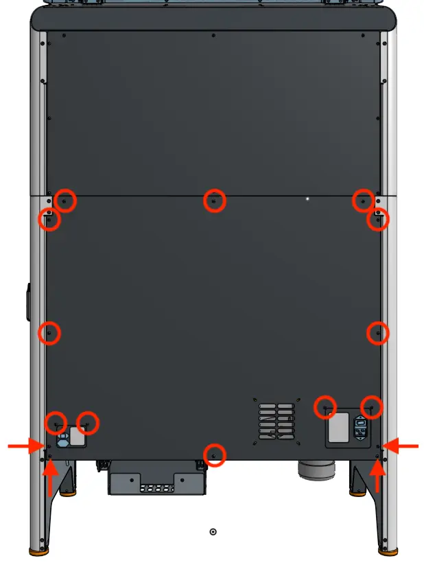
Use a 2.5 mm hex driver to remove the 16 black 8.0 mm M4 screws securing the rear panel to the Fuse Sift. Set the rear enclosure panel aside.

Fuse sift rear enclosure panel

Tip

Remove the top three screws last to prevent the panel from falling off.

Notice: 

The Fuse Sift contains sensitive electronic components. Ground yourself before touching any electronics in the device by using an antistatic wrist band.

Removing the motherboard

Overview: Open the motherboard enclosure and disconnect and remove the original motherboard.

Step 1: Prepare to replace the motherboard

Put on an antistatic wristband and connect it to a known ground point. Do not connect the wristband any surfaces that are powder-coated or painted.

Step 2: Remove the motherboard cover

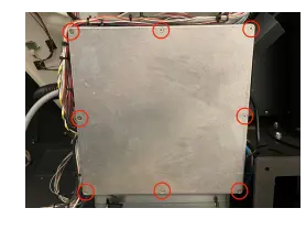
Locate the square motherboard cover on the rear of the machine. Using a #2 Phillips driver, loosen and remove the eight countersunk screws securing the cover onto the motherboard enclosure. Set the screws and cover aside.

Remove the original motherboard

Step 3: Disconnect the cables from the motherboard

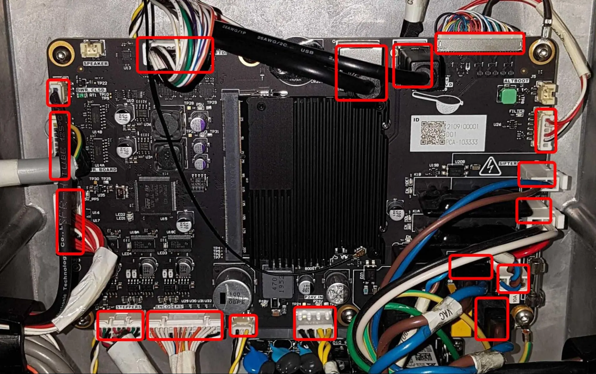
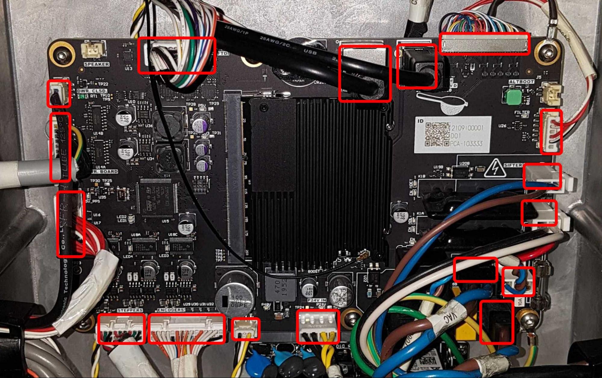
For your reference and for easier reinstallation, take a picture of the motherboard with all cables clearly visible. Disconnect all cables from the motherboard.

Remove the existing MoBo

Step 4: Disconnect the Wi-Fi antenna cable from the system on module (SOM)

Use a pair of ESD-safe tweezers to disconnect the Wi-Fi coaxial connector from the SOM. Take care when handling the cable and connector, as both are very fragile.

Remove the existing MoBo

Step 5: Unscrew the motherboard mounting screws

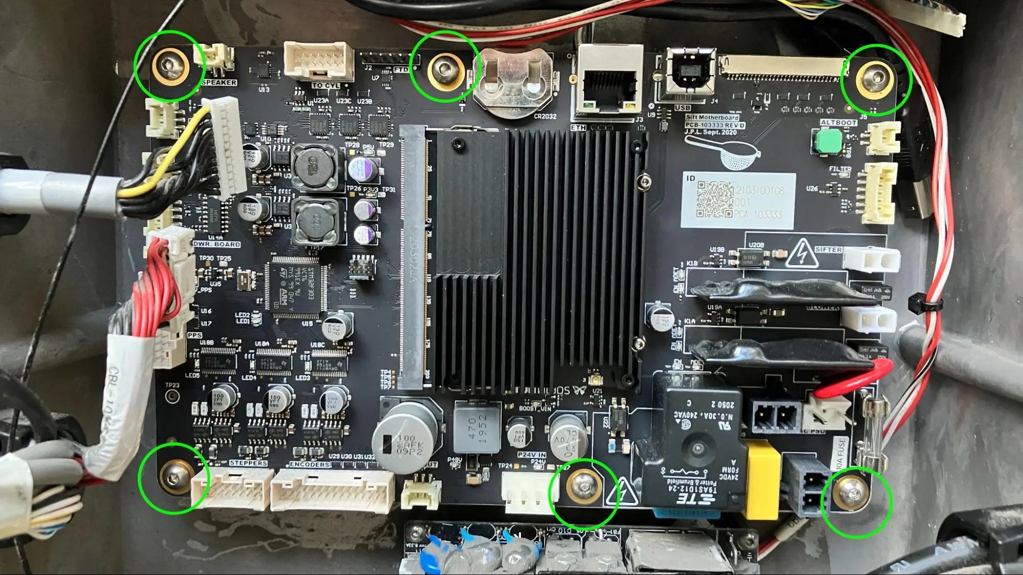
Using a 2.5 mm hex driver, loosen and remove the six 10.0 mm M4 screws securing the motherboard to its enclosure. Set the screws aside.

Step 6: Remove the motherboard

Carefully remove the motherboard from the Fuse Sift and set it aside on a flat, clean, anti-static work surface.

Remove the existing MoBo

Removing the SOM

Overview: Uninstall the SOM from the original motherboard to transfer to the replacement motherboard.

Step 1: Remove the SOM retention screws

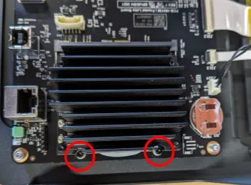
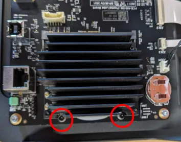
Using a 1.5 mm hex driver, loosen and remove the two 5 mm M2 socket head screws securing the SOM to the motherboard. Set the screws aside.

Remove the SOM

Step 2: Locate the SOM retention tabs

Remove the SOM
Remove the SOM

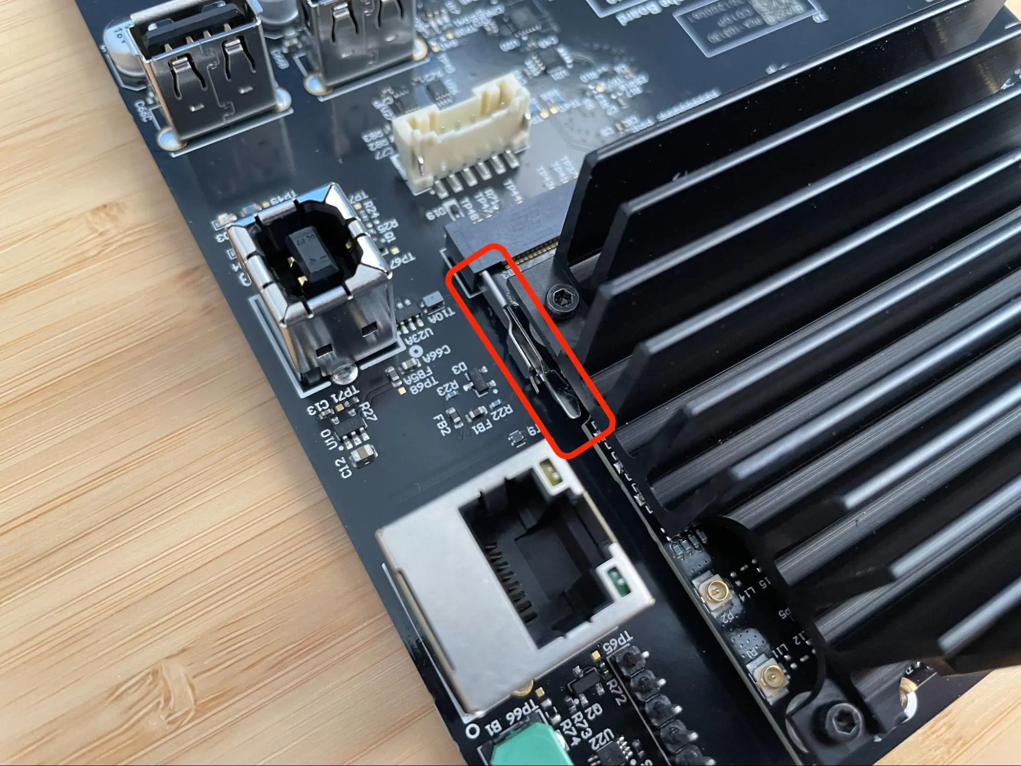
Locate the two retention tabs (one on each side) securing the SOM to the motherboard.

Step 3: Open the retention tabs

Use an ESD-safe spudger or a pair of ESD-safe tweezers to disengage the retention tabs by flexing them outwards slightly. The end of the SOM opposite the socket may lift up slightly.

Remove the SOM

Step 4: Remove the SOM

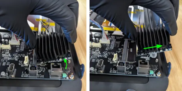
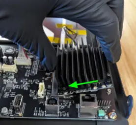
Gently grip the SOM by the heat sink, pivot it upwards at approximately a 30º angle, then pull it straight away from the motherboard. Set the SOM aside.

Remove the SOM

Installing the SOM into the replacement motherboard

Overview: Insert the SOM into its slot on the replacement motherboard and secure it in place.

Step 1: Prepare the replacement motherboard

Remove the replacement motherboard and place it on a flat, clean, anti-static work surface.

Step 2: Insert the SOM into its socket

Install the replacement SOM

Pick up the SOM by the heatsink, then insert it into the socket on the motherboard at approximately a 30º angle. Gently push the SOM into the socket so that none of the gold pins on the SOM are visible.

Step 3: Secure the SOM with the retention tabs

Push the SOM down onto the motherboard until the retention tabs snap into place.

Install the replacement SOM

Step 4: Fully secure the SOM

Thread one 5.0 mm M2 screw into both of the two screw holes in the SOM. Using a 1.5 mm hex driver, tighten until finger-tight.

Install the replacement SOM

Installing the replacement motherboard

Overview: After transferring the SOM, mount, secure, and connect the replacement motherboard.

Step 1: Check the replacement motherboard

Inspect the replacement motherboard and make sure that the battery and electrical fuse are already installed. If they are not, remove them from the original board and install them on the replacement board.

Install the replacement MoBo

Step 2: Mount the motherboard

Orient the motherboard with the battery on top and the fuse on the right. Place the replacement motherboard in the Fuse Sift motherboard enclosure, aligning the six screw holes in the motherboard with the corresponding screw holes in the enclosure standoffs.

Step 3: Partially secure the motherboard

Thread one 10.0 mm M4 screw into the left and center screw holes in the motherboard, circled in red here. Leave the two right-hand screw holes empty. Using a 2.5 mm hex driver, tighten the four screws until snug.

Step 4: Reconnect the grounding wires

Place the black ground wire ring terminal over the top-right motherboard screw hole. Secure the ground wire to the motherboard using a 10.0 mm M4 screw. Using a 2.5 mm hex driver, tighten until snug.

Place the green and green/yellow ground wire ring terminals over the bottom-right motherboard screw hole. Secure the ground wires to the motherboard using a 10.0 mm M4 screw. Using a 2.5 mm hex driver, tighten until snug.

Install the replacement MoBo

Step 5: Reconnect the Wi-Fi antenna cable

Use a pair of ESD-safe tweezers to reconnect the Wi-Fi coaxial connector to the SOM. Take care when handling the cable and connector, as both are very fragile.

Step 6: Connect the motherboard cables

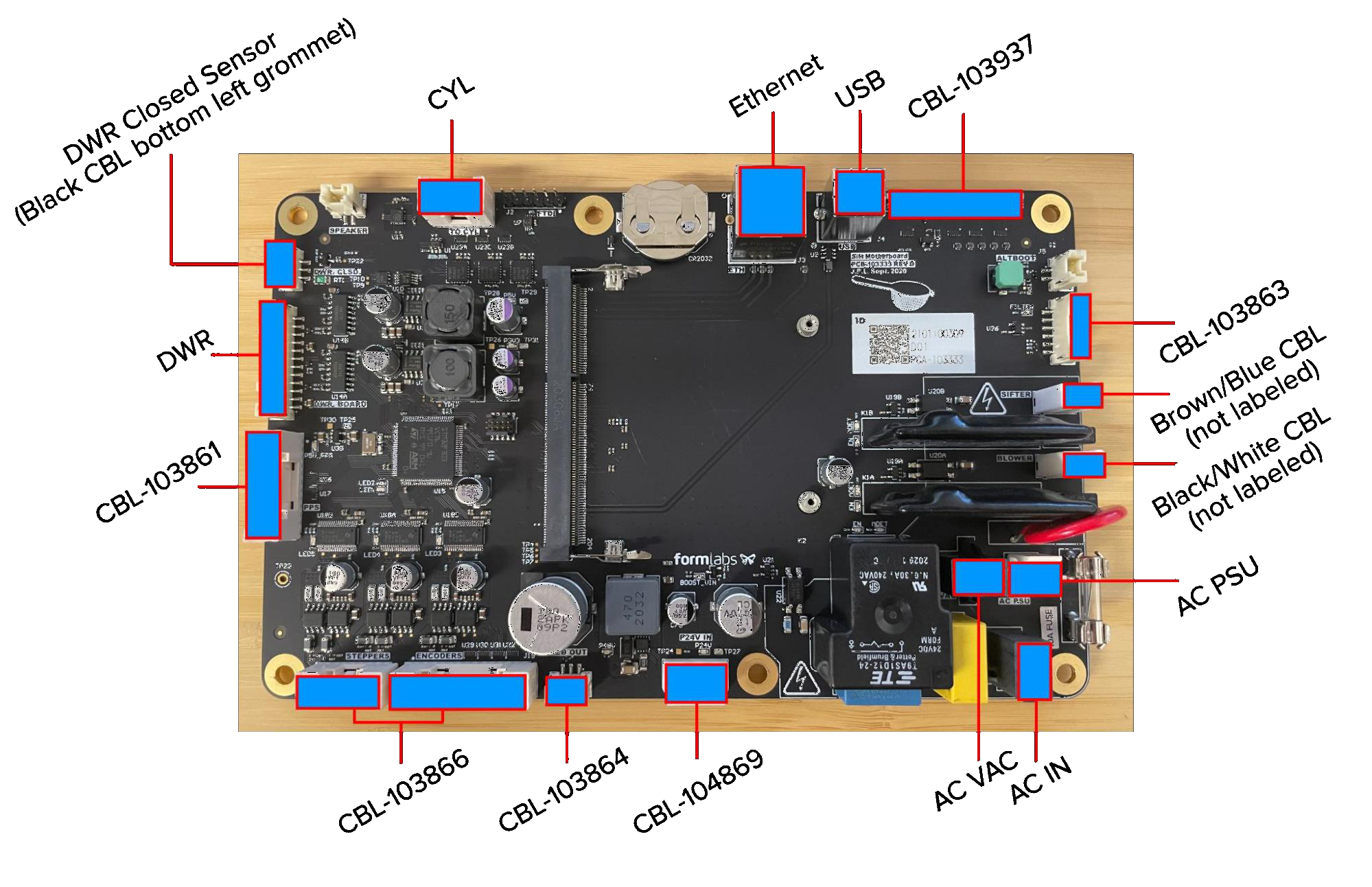
Reconnect all cable connectors to their respective sockets on the replacement motherboard. Refer to the image here to match each connector with its socket.

Install the replacement MoBo

Notice:

The display cable socket (labeled CBL-103937) on the motherboard is very delicate. Do not force the connector into the socket, or the replacement motherboard may be damaged.

Step 7: Reinstall the motherboard cover

Place the motherboard cover onto the motherboard enclosure, aligning the screw holes in the cover with the corresponding one around the edge of the enclosure. Thread one mounting screw into each of the eight screw holes, then use a #2 Phillips screwdriver to tighten until snug.

Replace the MoBo enclosure cover

Reinstalling the rear enclosure panel

Overview: Mount and secure the rear enclosure panel after installing the new display assembly and cable.

Step 1: Prepare the rear panel retention screws

Apply a small amount of Loctite 243 or other similar threadlocker to each of the 16 black 8.0 mm M4 button screws that secure the rear panel to the Fuse Sift.

Step 2: Mount the rear panel

Mount the rear panel onto the Fuse Sift.

Step 3: Secure the rear panel

Thread one 8.0 mm M4 button screw into each of the 16 screw holes in the rear panel. Use a 2.5 mm hex driver to tighten until snug.

Fuse sift rear enclosure panel

Tip:

Start with the top three screws to hold the panel in place while you thread and tighten the remaining screws.

Finalizing the repair

Overview: After installing the new motherboard, power on the Fuse Sift and test its functions.

Step 1: Power on the Fuse Sift

Reconnect the Fuse Sift to its power source. Flip the power switch to the ON position.

Step 2: Update firmware

Update the firmware to the latest version available. If the machine is on the latest firmware, manually reinstall it.

Step 3: Test the machine

Check that the Fuse Sift fully boots. Test various functions to ensure the machine works as expected. Contact Formlabs Support or your certified service provider to share the results of the procedure.