WHITE PAPER
Formlabs Logo

Replacing the Fuse Sift powder sensors

Replacing the Fuse Sift powder sensors

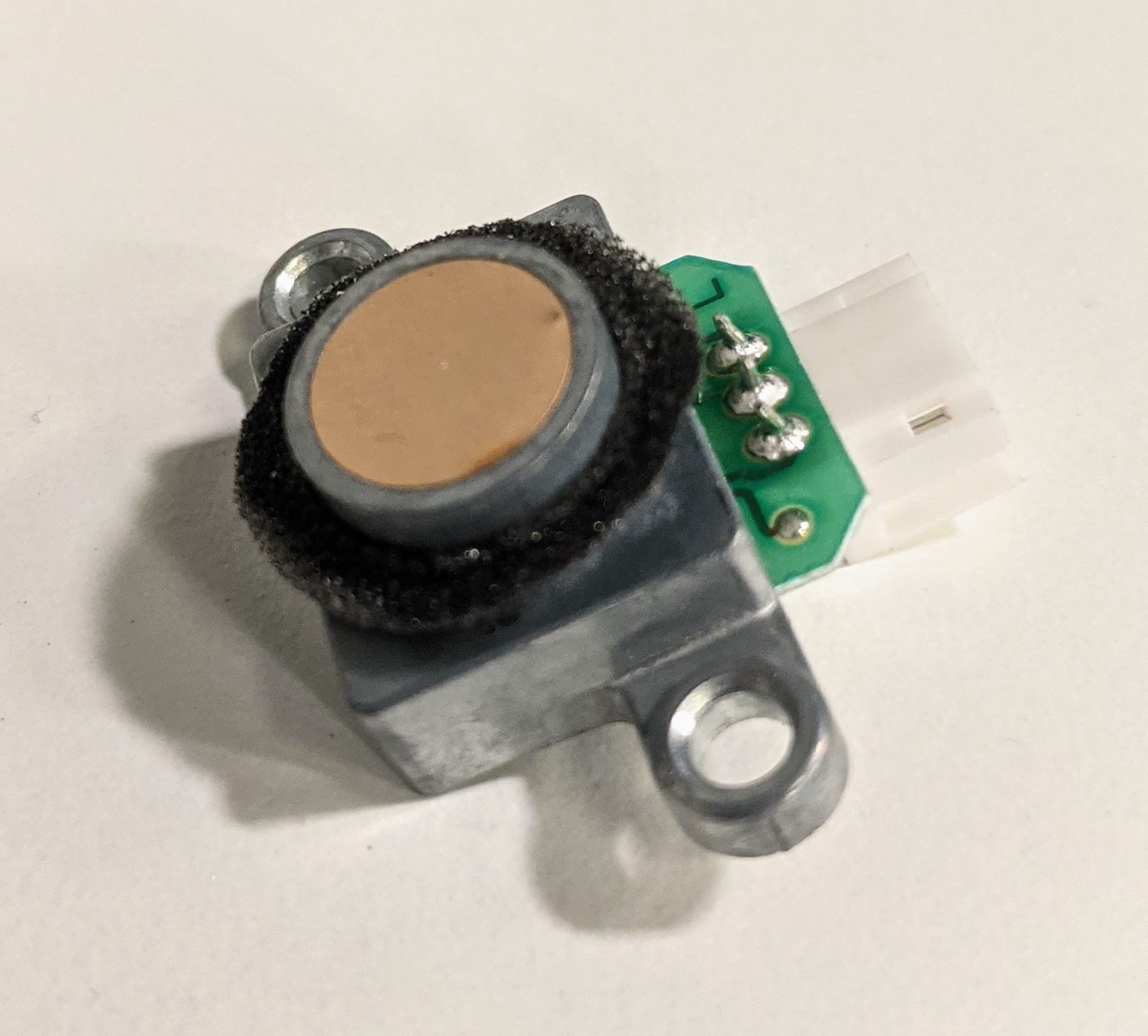
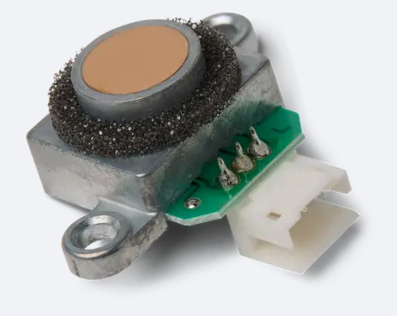
The Fuse Sift uses four sensors in the fresh powder hopper and used powder hopper to determine how much new and reclaimed powder is in the machine. If one or more of these powder sensors is faulty or malfunctioning, the Fuse Sift will not be able to properly track how much powder it contains.

Use this guide to replace the Fuse Sift powder sensors.

Fuse Sift powder sensor

Required Supplies:

Formlabs:

Third-party:

  • 2 mm hex driver (flat-end)
  • 2.5 mm hex driver (flat-end)
  • Loctite 243 or equivalent threadlocker
  • Appropriate personal protective equipment for the powder in use, as defined in the safety data sheet (SDS)
Estimated time: 30–45 minutes

Preparing the workspace

Overview: Prepare the Fuse Sift and your workspace for replacing one or more powder sensors.

Step 1: Remove and store printed parts

Remove any printed parts from the Fuse Sift workspace to prevent them from being damaged inadvertently.

Step 2: Clean the workspace

Using the vacuum attached to your Fuse Sift, clean the workspace. Vacuum any loose powder inside the workspace, under the hood, on the print bed and the surrounding port, and on the vent filter.

Warning:

Use appropriate personal protective equipment when handling loose or unsintered powder. Refer to the support article Safety with Formlabs SLS products or your powder’s safety data sheet (SDS) for more information.

Step 3: Empty the powder hopper(s)

Identify the powder hopper that has the sensor to be replaced. Empty that hopper to below the level of the faulty sensor to prevent powder from leaking out during the repair procedure. You can scoop powder into a separate container or dispense powder into a powder cartridge as normal.

Removing the rear enclosure panel

Overview: Remove the rear enclosure panel to better access the cartridge drawer components.

Step 1: Unplug the Fuse Sift

Power off the Fuse Sift, then unplug the power cable from the rear panel.

Danger:

Performing this procedure on the Fuse Sift while it is plugged in increases the risk of electric shock. After disconnecting the power from the Fuse Sift, wait at least five minutes before servicing.

Step 2: Unscrew the Wi-Fi antenna

Remove the Wi-Fi antenna, if present.

Step 3: Remove the rear enclosure panel

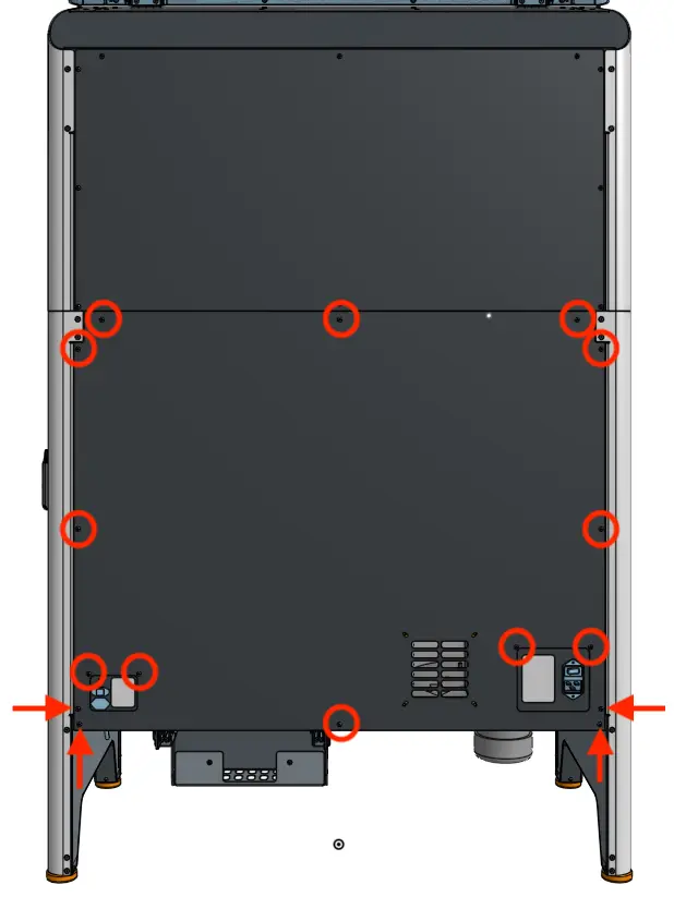
Use a 2.5 mm hex driver to remove the 16 black 8.0 mm M4 screws securing the rear panel to the Fuse Sift. Set the rear enclosure panel aside.

Fuse sift rear enclosure panel

Tip

Remove the top three screws last to prevent the panel from falling off.

Notice: 

The Fuse Sift contains sensitive electronic components. Ground yourself before touching any electronics in the device by using an antistatic wrist band.

Removing the powder sensor(s)

Overview: Identify and uninstall the faulty powder sensor(s).

Step 1: Locate the powder sensors

Replace the powder sensor(s)

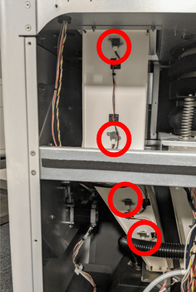
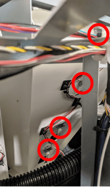
When looking at the Fuse Sift from the rear, the fresh powder hopper is on the left and the used powder hopper is on the right. Both hoppers have four small sensor boards spaced evenly along their height. Identify the powder sensor or sensors to be replaced.

Step 2: Disconnect the powder sensor cables

Replace the powder sensor(s)

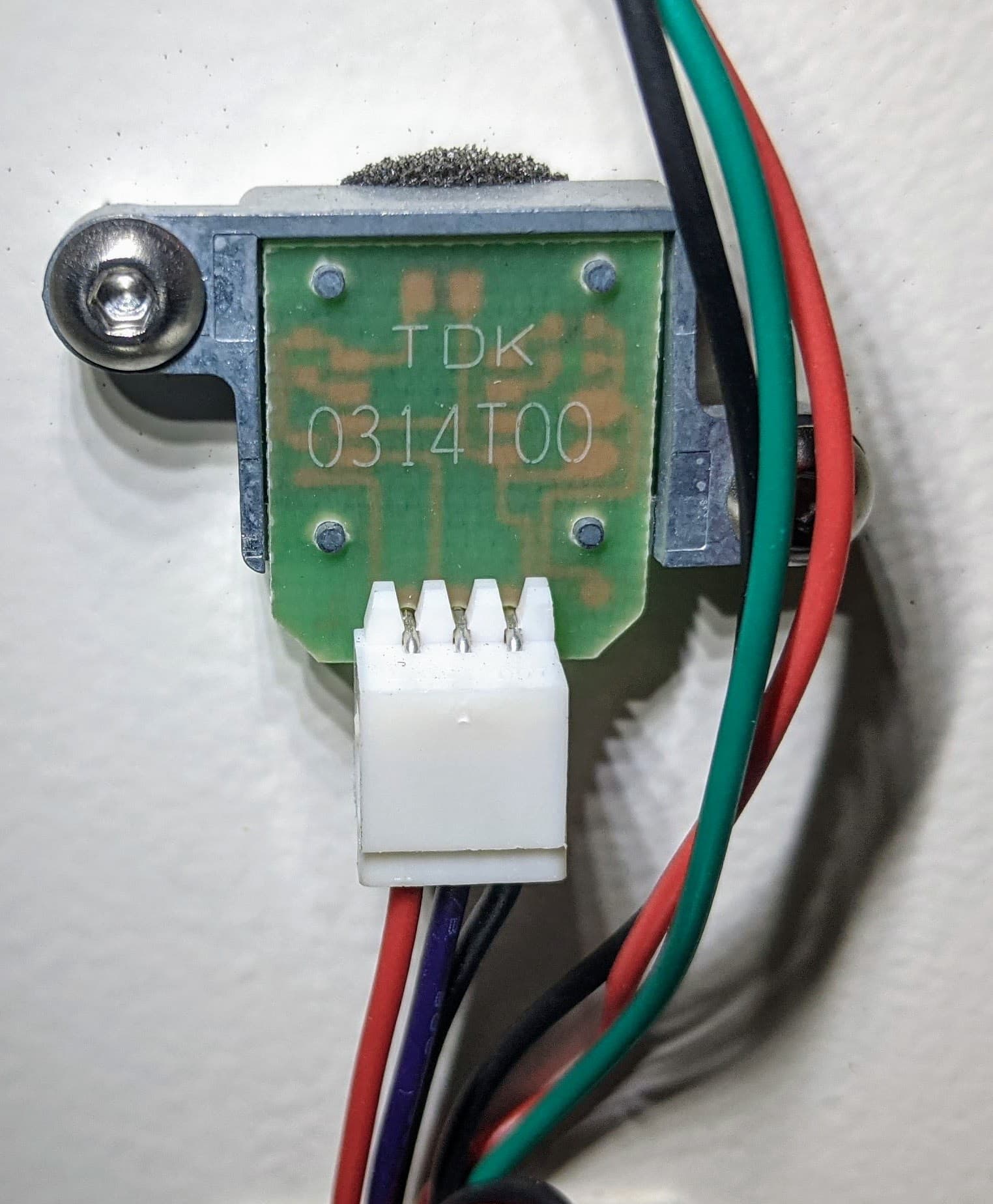
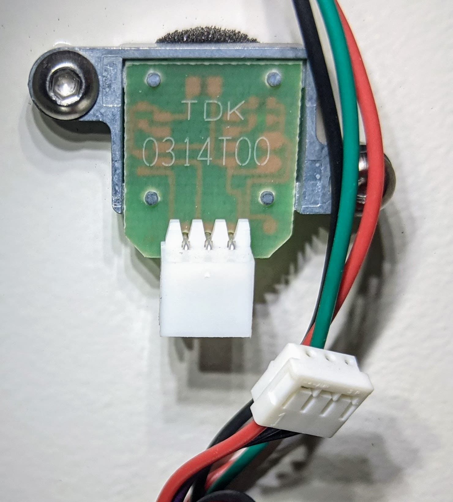
For each powder sensor you are replacing, disconnect the cable from the sensor board. Pull on the plastic connector, not the individual wires.

Step 3: Unscrew the powder sensor mounting screws

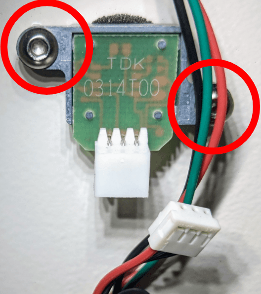
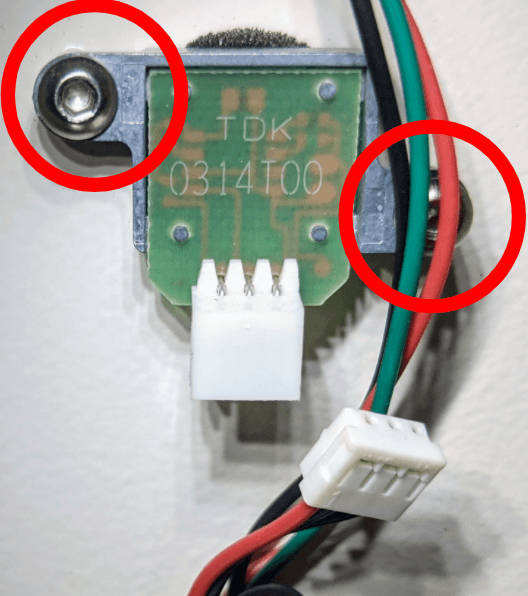
For each powder sensor you are replacing, use a 2 mm hex driver to loosen and remove the two 8 mm M3 button head screws securing the sensor to the hopper. Set the screws aside.

Step 4: Uninstall the powder sensors

Remove the powder sensors you are replacing from the hopper. Set the sensors aside for disposal with electronic waste.

Replace the powder sensor(s)

Installing the replacement powder sensor(s)

Overview: Mount, secure, and connect the replacement powder sensor(s).

Step 1: Prepare the replacement sensors

If you have not already, statically discharge yourself by touching a grounded metal surface or by putting on an antistatic wrist band and connecting it to a known ground point. Do not connect the wristband any surfaces that are powder-coated or painted.

Remove the replacement powder sensors from their packaging. If the new sensors do not have a foam gasket ring, transfer it from the old sensors.

Replace the powder sensor(s)

Step 2: Mount and secure the powder sensors

Place the round face of the new powder sensor into an open sensor hole in a hopper. Make sure that the cable connector is facing down and the two screw holes in the sensor board align with the corresponding holes in the hopper. Thread one 8 mm M3 button head screw into both screw holes. Using a 2 mm hex driver, tighten until snug. Repeat for any other powder sensors you are replacing.

Replace the powder sensor(s)

Step 3: Connect the powder sensor cables

Replace the powder sensor(s)

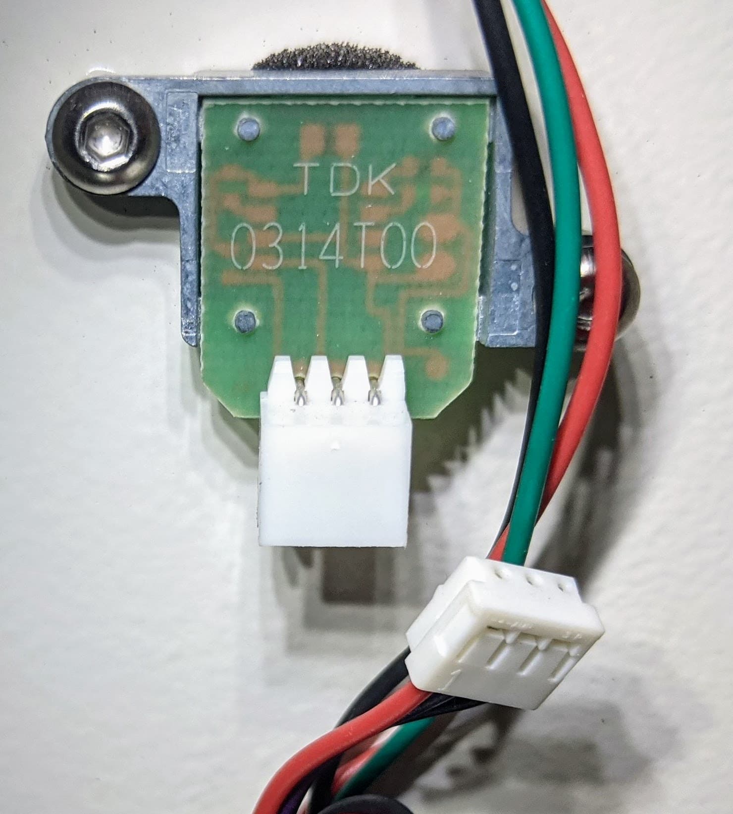
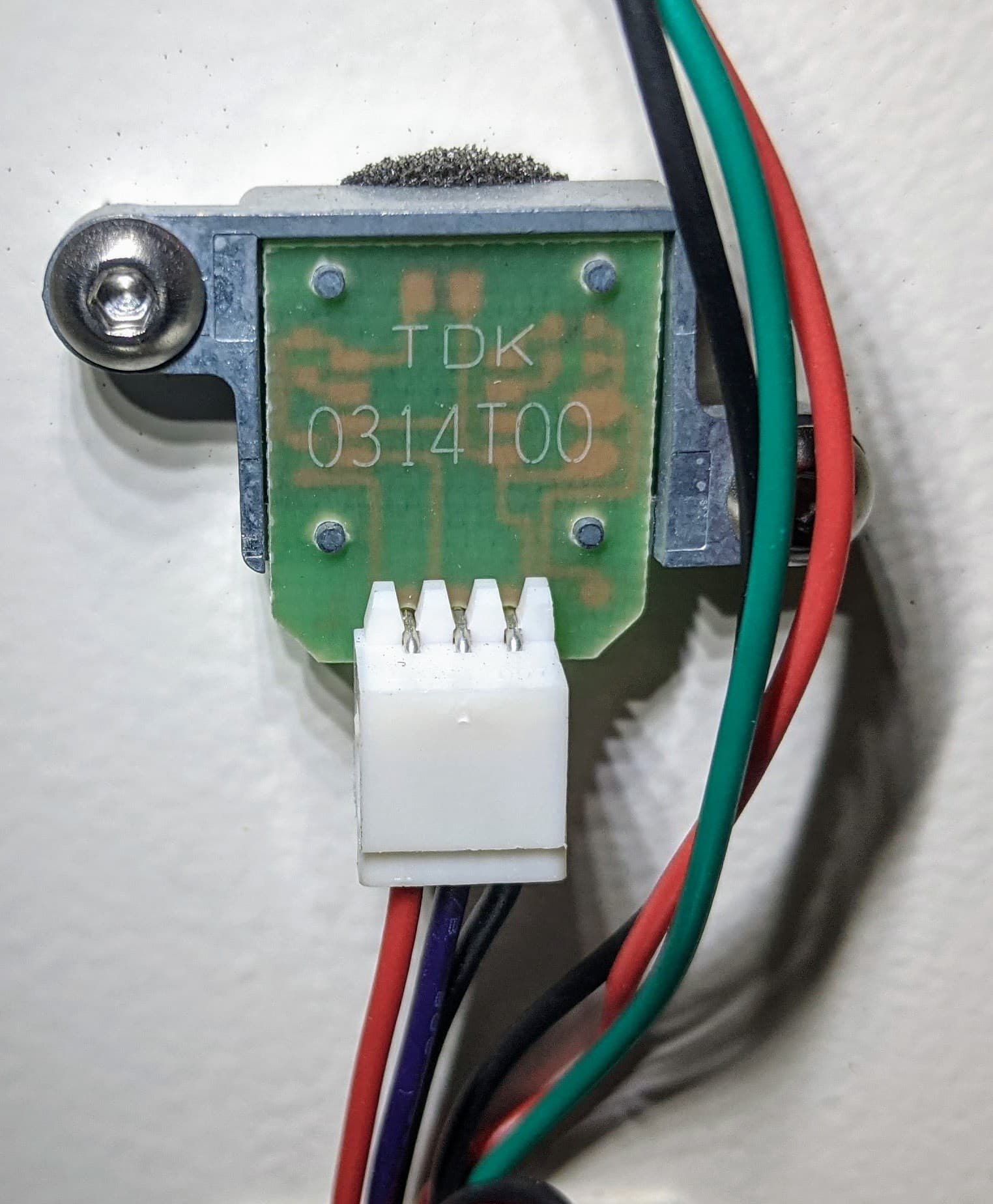
Connect the powder sensor cables to the new powder sensors. The cables are routed such that each should only be able to reach the correct sensor.

Reinstalling the rear enclosure panel

Overview: Mount and secure the rear enclosure panel after installing the new display assembly and cable.

Step 1: Prepare the rear panel retention screws

Apply a small amount of Loctite 243 or other similar threadlocker to each of the 16 black 8.0 mm M4 button screws that secure the rear panel to the Fuse Sift.

Step 2: Mount the rear panel

Mount the rear panel onto the Fuse Sift.

Step 3: Secure the rear panel

Thread one 8.0 mm M4 button screw into each of the 16 screw holes in the rear panel. Use a 2.5 mm hex driver to tighten until snug.

Fuse sift rear enclosure panel

Tip:

Start with the top three screws to hold the panel in place while you thread and tighten the remaining screws.

Finalizing the repair

Overview: After installing the new powder sensors, test that the Fuse Sift can measure the amount of powder in both hoppers.

Step 1: Power on the Fuse Sift

Reconnect the Fuse Sift to its power source. Flip the power switch to the ON position.

Step 2: Check the powder sensors

Refill the affected hopper(s) to above the level of the new powder sensor(s). Check that the display properly reflects the amount of powder in both hoppers. Contact Formlabs Support or your certified service provider to share the results of the procedure.