WHITE PAPER
Formlabs Logo

Replacing the Fuse Sift vibration motor

Replacing the Fuse Sift vibration motor

The Fuse Sift uses a motor to vibrate its sifter mesh and separate printed parts from unsintered powder. If the vibration motor is faulty or malfunctioning, it will be more difficult to post-process your parts and reclaim unsintered powder.

Use this guide to replace the Fuse Sift vibration motor.

Fuse Sift vibration motor

Required Supplies:

Formlabs:

  • Replacement Fuse Sift vibration motor
    • 120 V: RP-FS1-120-VB-01
    • 230 V: RP-FS1-230-VB-01

Third-party:

  • 2.5 mm hex driver (flat-end)
  • 6.0 mm hex driver
  • 6.5 mm slotted screwdriver
  • 12.5 Nm torque screwdriver with 6.0 mm hex bit
  • Flush cutters
  • Compliant vacuum with static dissipative components, such as a Class II, Division 2 vacuum
  • Vacuum brush tools
  • Zip ties
  • Antistatic wristband
  • Appropriate personal protective equipment for the powder in use, as defined in the safety data sheet (SDS)
  • Nonreactive nitrile gloves
  • Loctite 243 or equivalent threadlocker
Estimated time: 30–45 minutes

Removing the rear enclosure panel

Overview: Remove the rear enclosure panel to better access the cartridge drawer components.

Step 1: Unplug the Fuse Sift

Power off the Fuse Sift, then unplug the power cable from the rear panel.

Danger:

Performing this procedure on the Fuse Sift while it is plugged in increases the risk of electric shock. After disconnecting the power from the Fuse Sift, wait at least five minutes before servicing.

Step 2: Unscrew the Wi-Fi antenna

Remove the Wi-Fi antenna, if present.

Step 3: Remove the rear enclosure panel

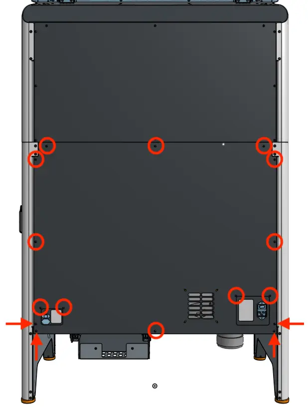
Use a 2.5 mm hex driver to remove the 16 black 8.0 mm M4 screws securing the rear panel to the Fuse Sift. Set the rear enclosure panel aside.

Fuse sift rear enclosure panel

Tip

Remove the top three screws last to prevent the panel from falling off.

Notice: 

The Fuse Sift contains sensitive electronic components. Ground yourself before touching any electronics in the device by using an antistatic wrist band.

Removing the vibration motor

Overview: Remove the original vibration motor and unplug it from the Fuse Sift motherboard.

Step 1: Unscrew the vibration motor mounting screws

Detach the vibration motor

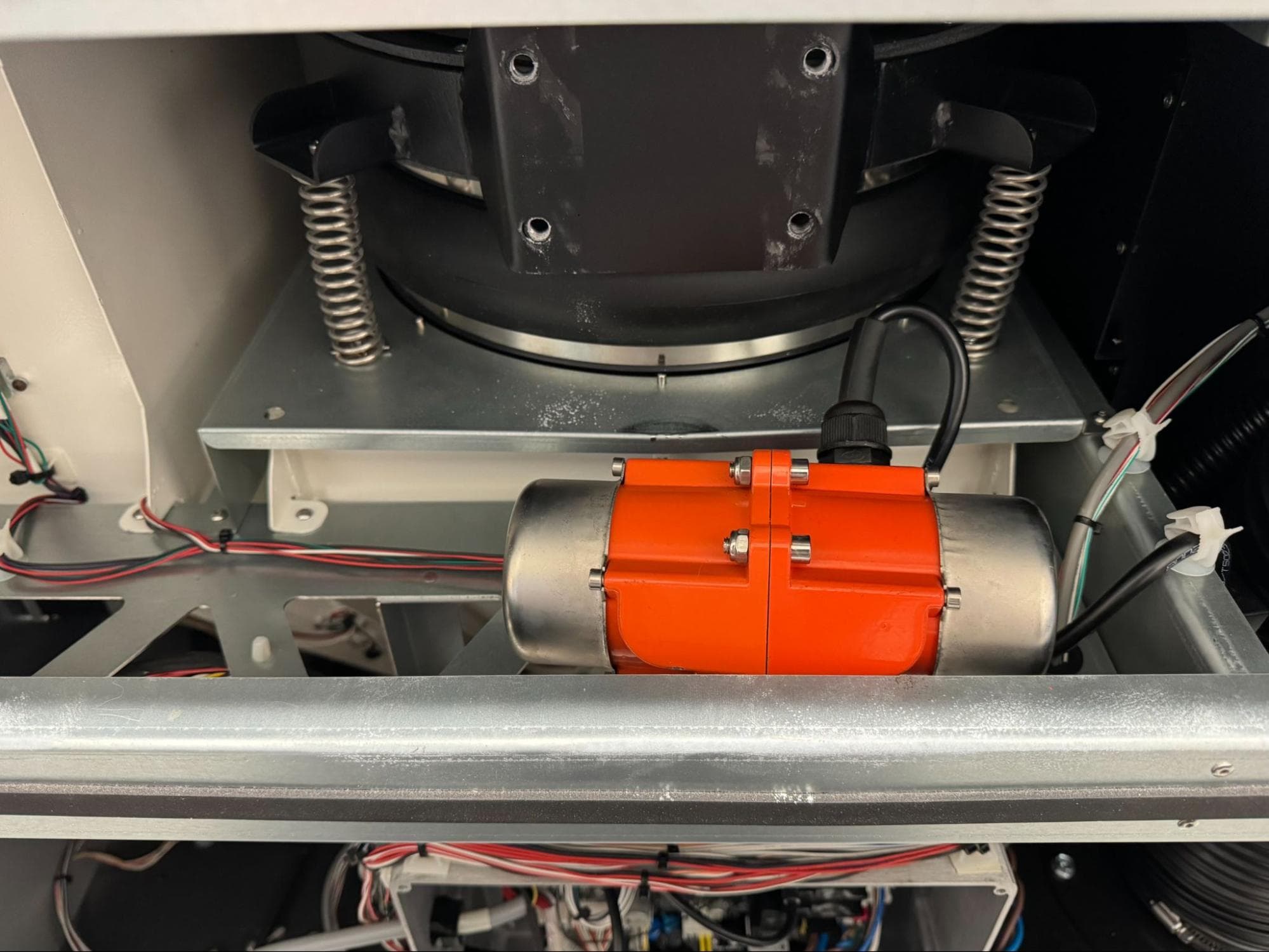
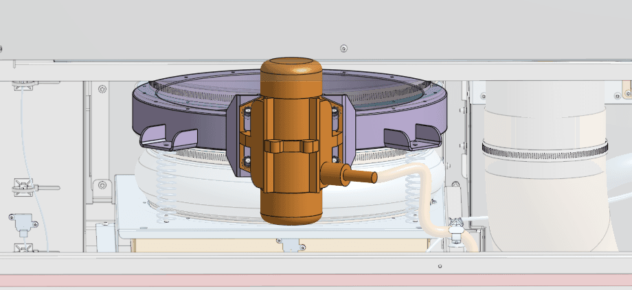
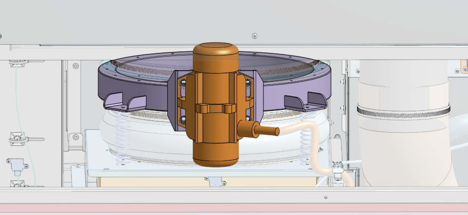
Locate the vibration motor, positioned on the back of the sifter assembly. Using a 6.0 mm hex driver, loosen and remove the four 20.0 mm M8 cap screws and lock washers securing the motor. Set the screws and lock washers aside.

You may need to use a ball-end hex driver or loosen the vibration motor cable gland to access all four screws.

Place the motor horizontally on the upper shelf assembly.

Step 2: Remove the motherboard cover

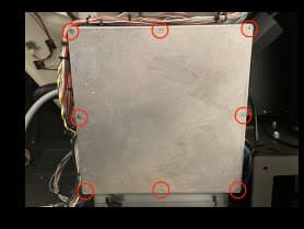
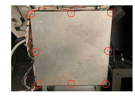
Locate the square motherboard cover on the rear of the machine. Using a #2 Phillips driver, loosen and remove the eight countersunk screws securing the cover onto the motherboard enclosure. Set the screws and cover aside.

Replace Inductive Sensor

Step 3: Disconnect the vibration motor cable

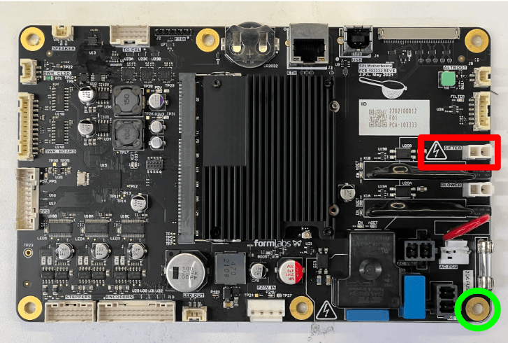
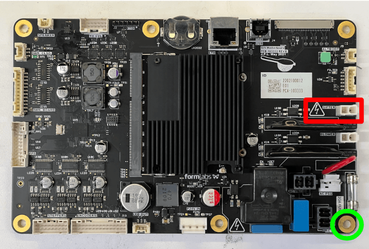
If you have not already, put on an antistatic wristband and connect it to a known ground point. Do not connect the wristband any surfaces that are powder-coated or painted. Disconnect the vibration motor cable from the port on the motherboard labeled SIFTER.

Using a 2.5 mm hex driver, loosen and remove the chrome 10.0 mm M4 screw securing the grounding ring terminal to the bottom-right corner of the motherboard.

Remove the vibration motor

Step 4: Separate the vibration motor cable from other wires

Remove the vibration motor

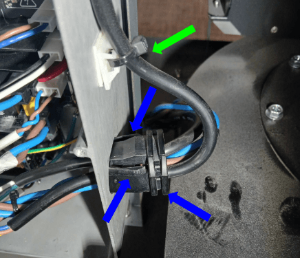
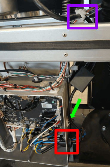
Locate the cord holder passing through the right side of the motherboard enclosure. Squeeze the three retention tabs and push it through to the outside of the enclosure.

Turn the grommet until the opening faces you. Pry apart the halves of the grommet with a flathead screwdriver. Feed the vibration motor’s cable out of the enclosure, remove the motor cable from the cable holder, then set it aside.

Use a pair of flush cutters to cut the zip tie on the outside of the motherboard enclosure, directly above the cable holder you just removed.

Follow the vibration motor cable upwards and separate it from the white plastic cable clamp.

Step 5: Remove the vibration motor

Remove the vibration motor from the Fuse Sift and set it aside for disposal with electronic waste. Take care not to pull on any other cables around the vibration motor while you remove it.

Installing the replacement vibration motor

Overview: Mount, secure, and connect the replacement vibration motor.

Step 1: Mount the vibration motor

Align the vibration motor with the four M8 taps on the back of the sifter assembly so that the motor’s cable is on the right-hand side.

Install the new vibration motor

Step 2: Secure the vibration motor

Place one lock washer onto each of the four vibration motor mounting screws. Apply a small dab of Loctite 243 or equivalent threadlocker to the threads of each screw. Thread one screw into each of the four screw holes in the motor and sifter assembly. Use a 6.0 mm hex driver to replace the 4X 20.0 mm M8 cap screws to secure the vibration motor to the sifter assembly.
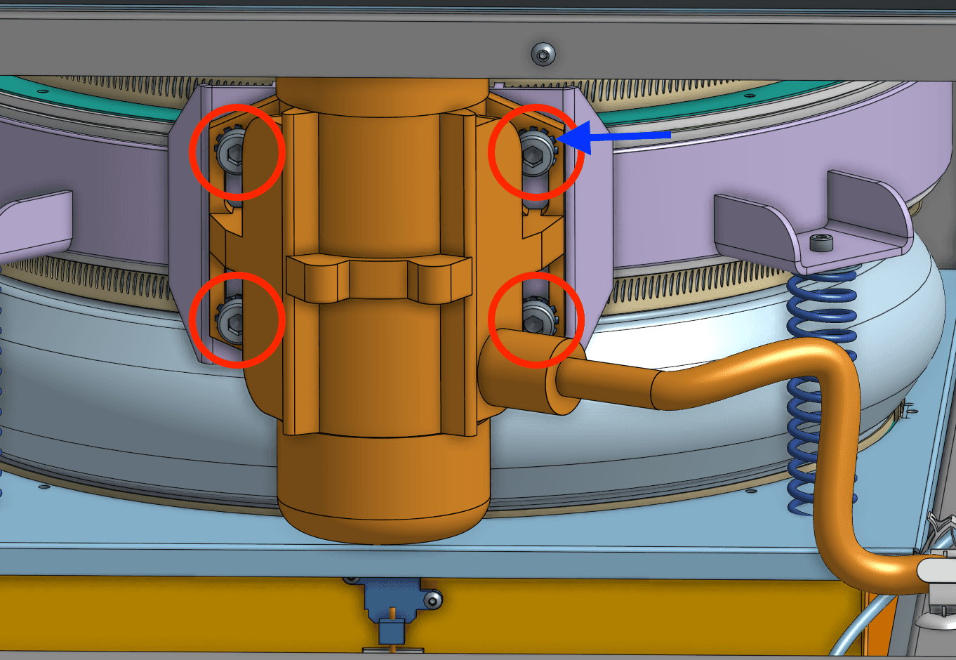
Step 3: Torque the vibration motor screws

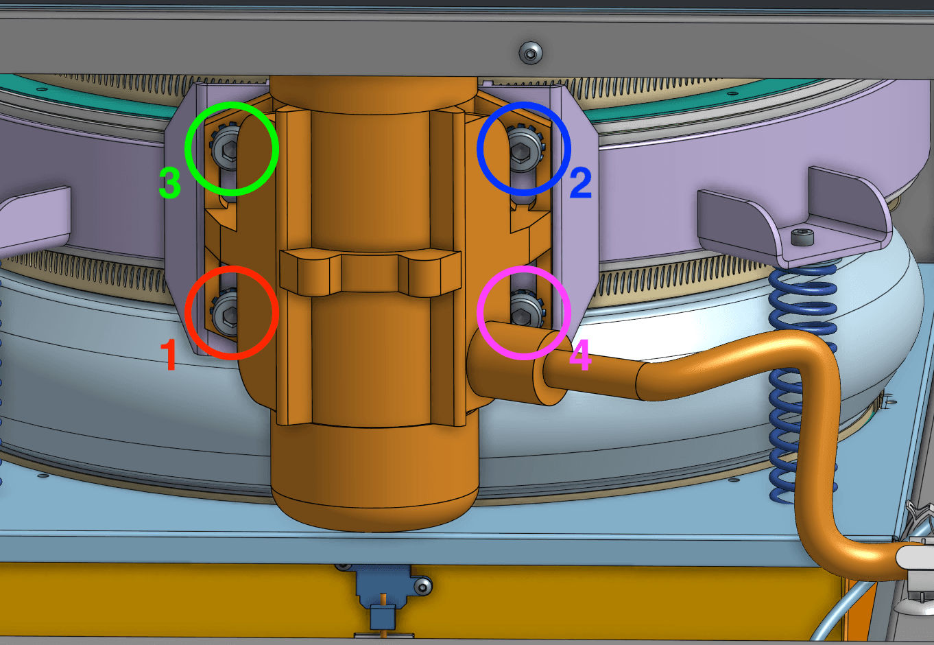
Use a torque screwdriver with a 6.0 mm hex bit to torque each of the vibration motor mounting screws to 12.5 Nm in the order depicted here.

You may need to use a ball-end hex driver or loosen the vibration motor cable gland to access all four screws.

Install the new vibration motor

Step 4: Route the vibration motor cable

Bundle the vibration motor cable with the other cables in the cord holder. Squeeze the cord holder shut. Route the vibration motor cable connector into the motherboard enclosure, then press the cord holder into its hole until retention tabs click into place.

Step 5: Connect the vibration motor cable

Connect the vibration motor cable to the socket on the motherboard labeled SIFTER. The socket is very fragile, so check that the cable connector is oriented correctly and do not force it into place.

Step 6: Reconnect the grounding ring terminal

Resecure the grounding ring terminal to the bottom-right corner of the motherboard using its chrome 10.0 mm M4 screw. Using a 2.5 mm hex driver, tighten until snug.

Vibration motor cable locations

Step 7: Reinstall the motherboard cover

Place the motherboard cover onto the motherboard enclosure, aligning the screw holes in the cover with the corresponding one around the edge of the enclosure. Thread one mounting screw into each of the eight screw holes, then use a #2 Phillips screwdriver to tighten until snug.

Replace the MoBo enclosure cover

Reinstalling the rear enclosure panel

Overview: Mount and secure the rear enclosure panel after installing the new display assembly and cable.

Step 1: Prepare the rear panel retention screws

Apply a small amount of Loctite 243 or other similar threadlocker to each of the 16 black 8.0 mm M4 button screws that secure the rear panel to the Fuse Sift.

Step 2: Mount the rear panel

Mount the rear panel onto the Fuse Sift.

Step 3: Secure the rear panel

Thread one 8.0 mm M4 button screw into each of the 16 screw holes in the rear panel. Use a 2.5 mm hex driver to tighten until snug.

Fuse sift rear enclosure panel

Tip:

Start with the top three screws to hold the panel in place while you thread and tighten the remaining screws.

Finalizing the repair

Overview: After installing the new vibration motor, power on the Fuse Sift and test its functions.

Step 1: Power on the Fuse Sift

Reconnect the Fuse Sift to its power source. Flip the power switch to the ON position.

Step 2: Test the sifter

Turn on the sifter using the Fuse Sift touchscreen. Check that it turns on, has sufficient force to sift powder, and that the machine does not make any unexpected noises. Contact Formlabs Support or your certified service provider to share the results of the procedure.