
備考:
PreForm設定エディタまたはサードパーティ製材料の使用には、プリンターが損傷する可能性などいくつかのリスクが伴います。リスクについては利用規約をご確認ください。

PreForm造形設定エディタでは、レーザー出力、速度、動作、加温を制御するさまざまな造形設定をカスタマイズすることで、Formlabs材料やサプライヤー認可済サードパーティ材料でのプリント性能を調整することができます。このツールは、プリントパラメータの調整方法と、その結果生じるあらゆる問題発生時の対処方法に精通している上級ユーザー様のみの使用を想定しています。カスタム造形設定でプリント中に問題が発生した場合、FormlabsサポートはFormlabsのデフォルト造形設定に戻すよう依頼します。カスタム造形設定の複雑性の理由で、微調整やカスタム造形設定の開発についてはサポート致しかねます。
備考:
PreForm設定エディタまたはサードパーティ製材料の使用には、プリンターが損傷する可能性などいくつかのリスクが伴います。リスクについては利用規約をご確認ください。
備考:
PreForm 3.41.0でFormlabs SLSプリンタ用の造形設定エディタが導入されました。PreFormを常にアップデートし、最新の造形準備機能をご利用ください。
チューニング入門
チューニングは、複数のパラメータの最適化に関わります。そのため、あるパラメータを変更すると、他のパラメータも変更が必要になることが多くあります。例えば、Perimeter Laser Powers(外周レーザー出力)を上げた場合、細部の寸法精度を同じレベルに保つためにPerimeter to Fill Spacing(外周から内側までの距離)を調整する必要があるかもしれません。
プリント性能は、モデルの形状、モデルの向きに大きく左右されます。作成したカスタム造形設定が、あるモデルにはうまく機能しても、別のモデルにはうまく機能しない場合もあります。作ったカスタム造形設定を定期的に使用する予定がある場合は、様々なモデルを使って、必ずカスタム造形設定をテストしてください。
プリンターの健全性の維持
備考:
パラメータ設定の組み合わせによっては、煙の発生、パウダーの燃焼、パウダーの広範囲にわたる溶融など、造形失敗やプリンターの損傷につながる可能性があります。Formlabs SLS プリンターで造形設定エディタを使用する前に、以下のガイドラインを読み、理解してください。
カスタム造形設定の作成
| Formlabsの造形設定に基づく | カスタム造形設定に基づく |
|---|---|
|
|
カスタム造形設定の編集
ヒント:
パラメータを変更した後、他のフィールドを編集中でない場合は、Print Settings Editorウィンドウの上部にあるUndo(元に戻す)ボタンをクリックすると、直前の変更を元に戻すことができます。カスタム造形設定のエクスポート
カスタム造形設定のインポート
カスタム造形設定の削除
ヒント:
すべてのカスタム造形設定をすばやく削除するには、Print Settings Editor(造形設定エディタ)画面の上部にあるDelete All(すべて削除)をクリックします。確認ウィンドウが表示されます。Delete All(すべて削除)をクリックして、すべてのカスタム設定を削除します。
カスタム造形設定でプリント
利用可能なパラメータ
Fuse 1世代
備考:
このセクションは現在作成中です。内容は変更される可能性があります。
| Name | Description | Units | Reasons to Modify | Common Issues |
|---|---|---|---|---|
| Layer Thickness | Thickness of a single layer of powder during printing. | mm | To adjust print speed, surface finish, or Z-axis fine feature performance. Increasing this value can improve print speed. Decreasing this value can improve surface finish or fine feature resolution. | Most parameters are tuned around layer thickness. If you change layer thickness, you need to adjust almost every other parameter to get optimal print results. |
| X Correction Factor | Scale factor for the X axis to account for print scale correction. | unitless | To adjust dimensional accuracy of large features (larger than several millimeters) in the X direction. This value is preset by Formlabs to compensate for the volumetric shrinkage of each Formlabs material. | |
| Y Correction Factor | Scale factor for the Y axis to account for print scale correction. | unitless | To adjust dimensional accuracy of large features (larger than several millimeters) in the Y direction. This value is preset by Formlabs to compensate for the volumetric shrinkage of each Formlabs material. | |
| Z Correction Factor | Scale factor for the Z axis to account for print scale correction. | Array field of Z positions, with unitless scale factors |
The Z Correction Factor array field defines a lookup table of Z height (mm) and scale factors. With one entry, it acts as a constant correction. With multiple entries, it linearly interpolates between them. Click Edit Array Field to open the table popup, where you can add, duplicate, edit, or delete points in the lookup table. 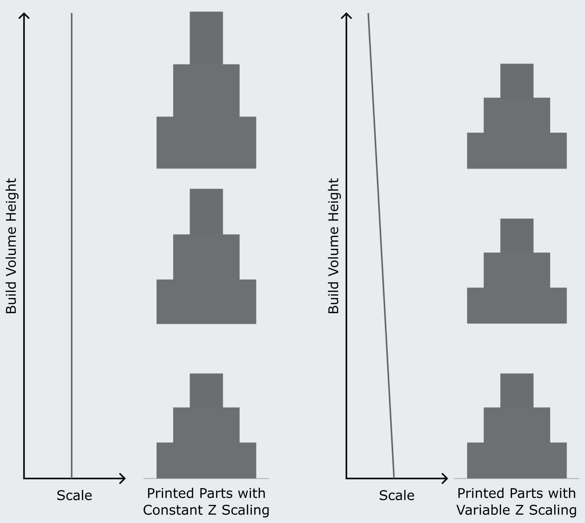
To paste data, use Ctrl/Cmd+P or the Paste button. You can paste 2-column tab-separated values copied from a spreadsheet (e.g., Google Sheets or Excel) or a JSON array of pairs (e.g., [[0, 1.0], [10, 1.1]]). The format is detected automatically. To copy data, use Ctrl/Cmd+C or the Copy button. This exports the table as tab-separated values. | |
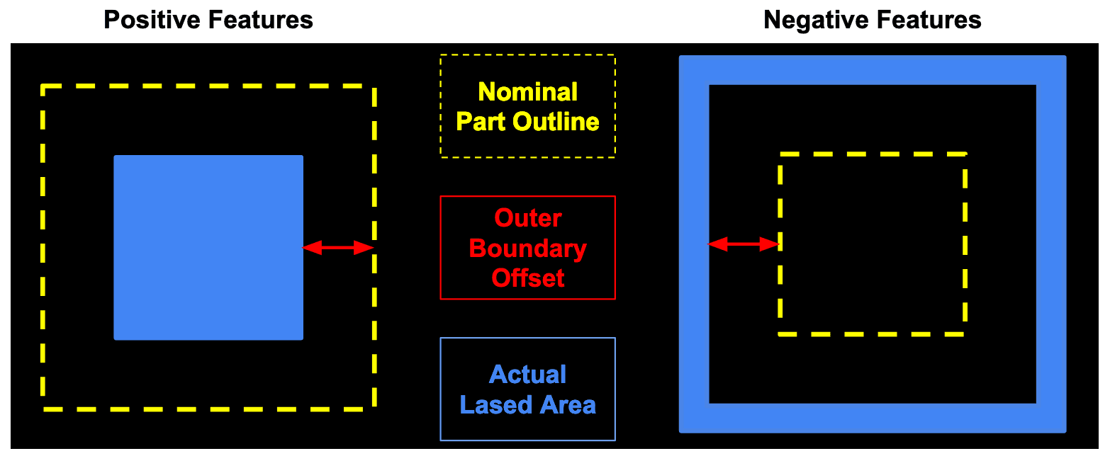
| Outer Boundary Offset | The space between the outermost perimeter laser path and the model's nominal boundary. A positive value means the laser perimeter will be inset smaller than the model's nominal boundary. | mm |
To correct for cases where small features (millimeter scale) are undersized or oversized.
| Changing this value too much can erode or dilate negative or positive features. For example, if you set this incorrectly, small negative holes might be filled in or small positive features might not print correctly. For additional information, see the section Visual examples of selected parameters below. |
| Fill Laser Power | Power output from the laser applied to the bulk fill of the model. | mW | To adjust energy delivery rate to the bed from the laser. Increasing this value can improve material properties. Decreasing this value can reduce dimpling and pitting defects. Overall fill laser exposure is a function of Fill Laser Power, Fill Laser Speed, and Fill Hatch Spacing. | High laser exposure can lead to surface artifacts or other symptoms of oversintering . Low laser exposure will result in brittle, weak parts and part curling. Changing the laser exposure will require tuning dimensional accuracy. |
| Fill Laser Speed | Speed the laser moves at across the bulk fill of the model. | mm/s | To adjust the laser speed at the bed. Increasing this value reduces smoking and print time. Decreasing this value can improve material properties. Overall fill laser exposure is a function of Fill Laser Power, Fill Laser Speed, and Fill Hatch Spacing . | Low laser speed (and therefore high laser exposure) can lead to surface artifacts or other symptoms of oversintering. Low laser exposure will result in brittle, weak parts and part curling. Changing the laser exposure will require tuning dimensional accuracy. |
| Fill Hatch Spacing | Spacing between adjacent scan lines within the bulk fill of the model. | mm | To change the exposure. Increasing spacing will result in more energy delivery to the print bed. Decreasing spacing will result in faster print times. Overall fill laser exposure is a function of Fill Laser Power, Fill Laser Speed, and Fill Hatch Spacing . | Close spacing (and therefore high laser exposure) can lead to surface artifacts or other symptoms of oversintering. Low laser exposure will result in brittle, weak parts and part curling. Changing the laser exposure will require tuning dimensional accuracy. |
| Upskin Layer Count | Number of layers where Upskin Laser Power is applied to the top surface of models. | layers | To change the number of layers the Upskin Laser Power parameter is applied to. | Too many upskin layers may result in Z inaccuracy or brittleness of thin parts. Too few upskin layers may result in poor top surface finish. For additional information, see the section Visual examples of selected parameters below. |
| Upskin Laser Power | Power output from the laser applied to the Upskin regions of the model. | mW |
To reduce energy delivery on top surface layers of parts. Reducing this parameter can reduce surface artifacts, such as dimpling and pitting, and make top surface finish more consistent. Note: Upskin Laser Power is applied with the Fill Hatch Spacing and Fill Laser Speed parameters. | If Upskin Laser Power is too high, top surface finish may be poor. If Upskin Laser Power is too low, thin parts may become brittle and layer delamination at the tops of parts may occur. |
| Downskin Layer Count | Number of layers where Downskin Laser Power is applied to the bottom surface of models. | unitless | To change the number of layers the Downskin Laser Power parameter is applied to. | Too many downskin layers may result in parts becoming too small in the Z direction or lead to brittleness of thin parts. Too few downskin layers may result in parts becoming too large in the Z direction. For additional information, see the section Visual examples of selected parameters below. |
| Downskin Laser Power | Power output from the laser applied to the Downskin regions of the model. | mW |
To reduce energy delivery on bottom surface layers of parts. Helps reduce downward thermal bleed and ensure correct feature size in Z. Note: Downskin Laser Power is applied with the Fill Hatch Spacing and Fill Laser Speed parameters. | If Downskin Laser Power is too high, parts may be too large in the Z direction. If Downskin Laser Power is too low, parts may become brittle or be too small in the Z direction. Layer delamination may also occur at the bottom of parts. |
| Fill Direction Rotations | Laser scan direction pattern. | Array field of layers, with angles in degrees | To change lasing direction by layer, which can improve thermal management of the build and can result in more uniform surface finish. | Some materials may exhibit increased Z-axis surface roughness when the laser fill direction is changed. Layer lines may become more apparent on vertical surfaces. |
| Perimeter Count | Number of adjacent contours within the perimeter region of the model. | unitless | To change the number of perimeter contours drawn by the laser, affecting the thickness of the perimeter region. Typically is set to 0, 1, or 2. If this value was originally set to 0, refer to the note below. | Increasing the number of perimeters will slow down printing and will result in excessive perimeter overlap with the fill if the Perimeter to Fill Spacing parameter is not adjusted. For additional information, see the section Visual examples of selected parameters below. |
| Perimeter Laser Powers | Power outputs from the laser applied to each perimeter region of the model. | Array field of perimeters, with laser power in mW | To adjust the energy rate to the perimeter region by the laser. Increasing perimeter power can result in stronger thin features in the X and Y directions and sharper edges of parts. Overall perimeter laser exposure is a function of Perimeter Laser Powers, Perimeter Laser Speed, and Perimeter Spacings. | High perimeter laser exposure can lead to surface artifacts or other symptoms of oversintering. Low perimeter laser exposure will result in brittle, weak parts and part curling. Changing the laser exposure will require tuning dimensional accuracy. |
| Perimeter Laser Speed | Speed the laser moves along the perimeter region of the model. | Array field of layers, with laser speed in mm/s | To adjust the laser speed at the perimeter region by the laser. Increasing this value reduces smoking and reduces print time. Decreasing this value can improve fine feature strength in the X and Y directions and sharpen part edges. Overall perimeter laser exposure is a function of Perimeter Laser Powers, Perimeter Laser Speed, and Perimeter Spacings. | High perimeter laser exposure can lead to surface artifacts or other symptoms of oversintering. Low perimeter laser exposure will result in brittle, weak parts and part curling. Changing the laser exposure will require tuning dimensional accuracy. |
| Perimeter Spacings | Spacings between adjacent contours within the perimeter region of the model. | Array field of perimeters, with perimeter spacing in mm | To increase or decrease spacing of adjacent contours within the perimeter region. Larger spacing results in lower energy density for the region. Smaller spacing results in higher energy density. Overall perimeter laser exposure is a function of Perimeter Laser Powers, Perimeter Laser Speed, and Perimeter Spacings. | High perimeter laser exposure can lead to surface artifacts or other symptoms of oversintering. Low perimeter laser exposure will result in brittle, weak parts and part curling. Changing the laser exposure will require tuning dimensional accuracy. For additional information, see the section Visual examples of selected parameters below. |
| Perimeter to Fill Spacing | Distance from the outermost perimeter to the fill region. | mm | To change positioning of the perimeter region relative to the fill region. A negative number causes fill to overlap entirely with the perimeter region. A positive number allows some of the perimeter region to fall outside the fill region. | Too large of a positive overlap can cause the perimeter region to become discontinuous with the fill and result in poor material properties. Too small of an overlap can result in surface artifacts from the perimeter region being superimposed on the fill. For additional information, see the section Visual examples of selected parameters below. |
| Perimeter Upskin Laser Power | Power outputs from the laser applied to each contour within the upskin portion of the perimeter region. | Array field of perimeters, with laser power in mW | To modify energy deliver to contours on the top layers of parts. Generally used to decrease power, not increase it. | If Perimeter Upskin Laser Power is too high, layer edges will be more pronounced on top surfaces. If Perimeter Upskin Laser Power is too low, perimeters will not resolve on top layers and material properties may suffer. |
| Perimeter Downskin Laser Power | Power outputs from the laser applied to each contour within the downskin portion of the perimeter region. | Array field of perimeters, with laser power in mW | To modify energy delivery to contours on the bottom layers of parts. Generally used to decrease power, not increase it. | If Perimeter Downskin Laser Power is too high, layer edges will be more pronounced on bottom surfaces. If Perimeter Downskin Laser Power is too low, perimeters may not resolve on bottom layers and material properties may suffer. |
| Armor Laser Power | Power output of the laser to the Surface Armor regions surrounding the model. | mW | To change Surface Armor stiffness and reduce curling and birchbark artifacts. | If Surface Armor laser exposure is too low, birchbark and part curling become more common. If it is too high, Surface Armor may become more difficult to remove and may curl and drag within the print bed. |
| Armor Laser Speed | Speed the laser moves at within the Surface Armor regions surrounding the model | mm/s | To change Surface Armor stiffness and reduce curling and birchbark artifacts. | If Surface Armor laser exposure is too low, birchbark and part curling become more common. If it is too high, Surface Armor may become more difficult to remove and may curl and drag within the print bed. |
| Armor Spacing | Spacing between adjacent scan lines within the Surface Armor regions surrounding the model. | mm | To change Surface Armor stiffness and reduce curling and birchbark artifacts. | If Surface Armor laser exposure is too low, birchbark and part curling become more common. If it is too high, Surface Armor may become more difficult to remove and may curl and drag within the print bed. |
| Armor Thickness (XY) | Thickness of the Surface Armor region around the model in XY. | mm | To change how thick the Surface Armor region is. Thinner Surface Armor means less material to remove from the surface of the part, while thicker Surface Armor may be more stable. | If Armor Thickness (XY) is too low, poor surface finish and part curling become more likely. If Armor Thickness (XY) is too high, there will be significantly more Surface Armor to remove from the bottom of parts. For additional information, see the section Visual examples of selected parameters below. |
| Armor Depth (Z) | Thickness of the Surface Armor region that is lased below the part in Z, measured in layers. | unitless | To change how much armor is printed below the parts. Armor Depth (Z) is primarily used to reduce the likelihood of curling. | If Armor Depth (Z) is too low, curling becomes more likely. If Armor Depth (Z) is too high, there will be significantly more Surface Armor to remove from the bottom of parts. For additional information, see the section Visual examples of selected parameters below. |
| Air Heater Set Points | Temperature set points for the air heater, and the heights at which they're applied. | Array field, with set points in °C and heights in mm | To change air heater output. The air heater output can shift thermal uniformity within the print bed. | If the air heater temperature is too high, the rear of the print bed will be hotter than the front and some melting may occur. If the air heater temperature is too low, the front of the print bed may be hotter than the rear. |
| Bed Temperature Set Points | Temperature set points for the bed prior to lasing, and the heights at which they're applied. | Array field, with set points in °C and heights in mm | To change bed target temperature. This is the primary temperature of the powder before lasing, controlled via energy output from the quartz tubes. | If the bed temperature is too high, the powder cake can become stiff, parts can become oversintered and inaccurate, and powder may melt prematurely. If the bed temperature is too low, birchbark artifacts become more likely, part curling becomes more likely, and significantly more laser energy is required to melt model regions. |
| Quartz Heater Gain Multiplier - Heating | Limits the total output of the quartz tube heaters during precoats. | Array field, with set points in °C and heights in mm | To modify the rate of thermal energy output delivered to the bed by the quartz tubes. Reducing quartz tube output results in a slower, more even heating of the powder before lasing. | If this parameter is set too low, a layer may not be able to reach the target bed temperature. |
| Quartz Heater Gain Multiplier - Printing | Limits the total output of the quartz tube heaters during printing. | Array field, with set points in °C and heights in mm | To modify the rate of thermal energy output delivered to the bed by the quartz tubes. Reducing quartz tube output results in a slower, more even heating of the powder before lasing. | If this parameter is set too low, a layer may not be able to reach the target bed temperature. |
| Buffer Trough Temperature Set Points | Temperature set points for the buffer trough during printing, and the heights at which they're applied. | Array field, with set points in °C and heights in mm | To adjust the powder preheating step before recoating. Increasing powder preheating reduces the heating load from the quartz tubes and can help improve thermal uniformity of a layer. | If the trough temperature is too high, powder flow and recoating can become worse, and powder can melt in the troughs preventing correct trough operation. If trough setpoints are too low, curling may be more likely during recoating. |
| Hopper Trough Temperature Set Points | Temperature set points for the hopper trough during printing, and the heights at which they're applied. | Array field, with set points in °C and heights in mm | To adjust the powder preheating step before recoating. Increasing powder preheating reduces the heating load from the quartz tubes and can help improve thermal uniformity of a layer. | If the trough temperature is too high, powder flow and recoating can become worse, and powder can melt in the troughs preventing correct trough operation. If trough setpoints are too low, curling may be more likely during recoating. |
| Upper Wall Temperature Set Points | Temperature set points for the upper wall heater during printing, and the heights at which they're applied | Array field, with set points in °C and heights in mm | To adjust the upper wall temperature so that sufficient energy is delivered to the edges of the bed. Increasing upper wall temperature can help with bed edge curling. | If the upper wall temperature is too high, powder around the edges of the build can melt and be dragged into the printable area. If upper wall temperature is too low, part curling or birchbark at the edges of the bed may occur. |
| Lower Wall Temperature Set Points | Temperature set points for the lower wall heater during printing, and the heights at which they're applied | Array field, with set points in °C and heights in mm | To adjust the temperature the powder cake and parts experience below the printing plane. Useful for addressing part warping and Z inaccuracy. | If the lower wall temperature is too high, powder can experience unnecessary aging and potentially melt into the piston top, resulting in stalled or damaged build chambers. |
| Piston Top Temperature Set Points | Temperature set points for the piston top heater during printing, and the heights at which they're applied. | Array field, with set points in °C and heights in mm | To adjust the temperature of the powder at the start of a print. The piston top temperature is very important for early print thermal uniformity. | If the piston top temperature is too high, powder at the bottom of the build may melt into the piston top and result in stalled or damaged build chambers. If the piston top temperature is too low, part curling may occur early in the print. |
| Pre-Lase Dwell Time | Time the printer waits between recoating and laser firing. | seconds | To allow additional time for powder temperature to equilibrate through a newly recoated layer. | |
| Post-Lase Dwell Time | Time the printer waits after laser firing and before recoating a new layer. | seconds | To allow additional time for melt cooling to occur before recoating a new layer. | If the Post-Lase Dwell Time is too short, thermal energy may accumulate in parts and result in dimensional inaccuracy and poor surface finish or surface defects. |
| Minimum Layer Time | Minimum time the printer spends on each layer. If a layer completes faster, the printer waits for the remaining time. | seconds | To allow additional time for melt cooling to occur before recoating a new layer. | If the Minimum Layer Time is too short, thermal energy may accumulate in parts and result in dimensional inaccuracy and poor surface finish or surface defects. |
| Recoater Speed | The speed the recoater moves across the bed between layers. | mm/s | To change the recoater motion and powder recoating behavior. | If the Recoater Speed is too high, top surface defects can occur from uneven recoating. |
| Powder Dosing Ratios | Angle of the trough flippers during powder dosing and recoating, and lased area fractions to apply at each angle. | Array field, with flipper angles in degrees and area fractions in unitless numbers. | To control the amount of powder dosed for multiple lased areas, ensuring a balance of sufficient recoating and reduced overdosed material. | If flipper dose angles are too low, layers will underdose and prints will fail. If flipper dose angles are too high, powder will accumulate outside the print area and can cause defects during recoating. |
| Precoat Thickness | Total thickness of powder introduced during preheating and before laser firing. | mm | To provide time for the thermal profile within the printer to stabilize and create a buffer layer between the printed parts and the piston top. | If Precoat Thickness is too small, the printer will not have enough time to preheat powder. This can cause defects or a print failure |
| Precoat Dwell Time | Time to pause after each individual precoat. | seconds | To control the individual recoat time within the precoat portion of the build. | If Precoat Dwell Time is too short, the printer will not have enough time to preheat powder. This can cause defects or a print failure. |
| Postcoat Thickness | Total thickness of powder added on top of a build after the final part is printed. | mm | To change the amount of powder added on top of a build. Increasing Postcoat Thickness can help with warping of parts printed last. | If Postcoat Thickness is too low, parts printed last are more likely to warp. If Postcoat Thickness is too high, prints may run out of powder before completing. |
選択したパラメータの追加説明と可視化
以下は、選択したパラメータと他のパラメータとの関係性を視覚的に表したものです。この例を参考に、各パラメータを変更することで造形品にどのような影響があるかを確認してください。
外周オフセット
外周オフセットは、最外周のレーザー軌道とモデルの公称境界との間の距離を設定します。レーザー焦点サイズと広がりを考慮するため、SLSで細かなフィーチャーに対して高い精細度を維持するのに役立ちます。下図では、実際のレーザー走査エリアに内側のエリアと外周エリアの両方が含まれています。
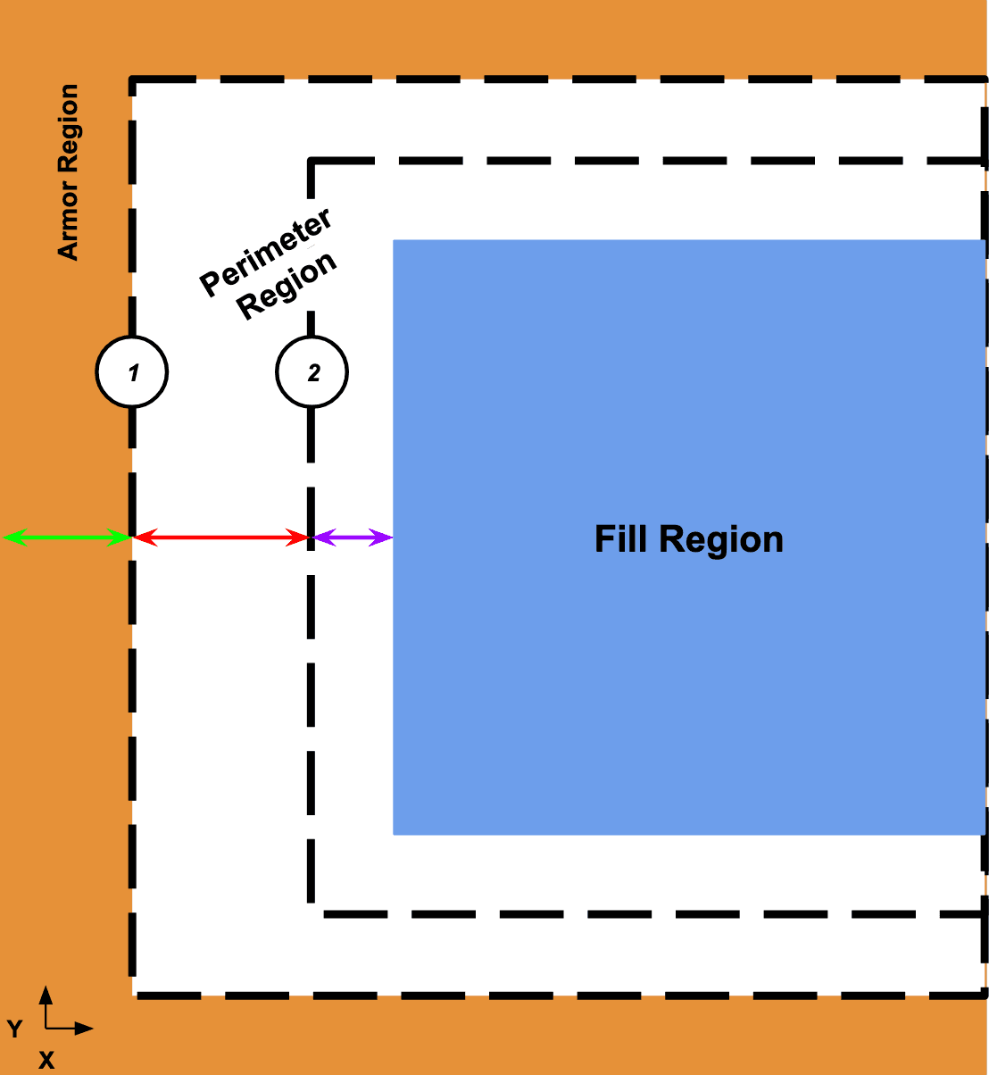
Armor Thickness(Surface Armorの厚さ)、Perimeter Count(外周の数)、Perimeter Spacings(外周の間隔)、Perimeter to Fill Spacing(外周から内側までの距離)の関係性
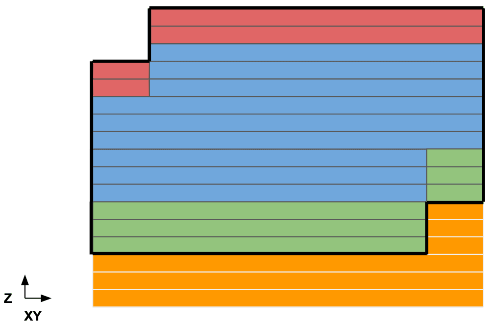
Upskin Layer Count(最上層部のレイヤー数)、Downskin Layer Count(最下層部のレイヤー数)、Armor Depth(Armorの奥行き)の関係性
Surface Armor
Surface Armorは、造形品の周囲に追加される部分的に焼結された材料の層です。これにより、物理的特性が向上し、反りのリスクが低減され、一般的に造形品の品質が向上します。Surface Armorは取り外しが難しい場合があるため、アーマーが厚いと造形品の取り出しや材料のクリーニングが難しくなる可能性があります。
外周数
外周数が0に設定されている場合、この設定で使用されるスキャンアルゴリズムには外周が含まれません。外周を追加しても全く機能しないか、予期せぬ動作をする可能性があります。外周のない材料設定はほとんどが古いレガシー設定です。外周のある設定を開発する際は、より新しい設定を出発点として使用してください。