WHITE PAPER
Formlabs Logo

Replacing the Fuse 1+ 30W doser assembly

Replacing the Fuse 1+ 30W doser assembly

In Fuse 1 generation printers, the doser controls the flow of powder from the hopper into the hopper trough before it is spread by the recoater. A faulty or malfunctioning doser will prevent the printer from printing normally.

Use this guide to replace the doser assembly on a Fuse 1+ 30W printer. To replace this component on a Fuse 1 printer, see Replacing the Fuse 1+ 30W doser assembly.

Fuse 1 doser assembly

Required supplies:

Formlabs:

Third-party:

Estimated time: 45–60 minutes, plus time to empty the powder hopper and print the hopper vacuum attachment, if needed

Danger:

Read and follow all safety instructions and warnings in the operator manual. Replacement with incorrect parts can lead to burns, shock, fire, or explosion. Dispose of all parts in accordance with local regulations.

Warning:

Do not perform this procedure if the printer was printing less than six hours prior. Failure to do so may result in serious burns. Allow the print enclosure to cool to room temperature before touching or inspecting any Fuse 1 components.

Preparing the workspace

Overview: Prepare the printer and a dust-free workspace for replacing the doser assembly.

Notice:

Fuse 1 generation printers contain sensitive electronic components. Ground yourself before touching any electronics in the printer by using a grounding strap or touching a grounded piece of metal.

Step 1: Print the hopper vacuum attachment

If you have access to another 3D printer or your Fuse 1 generation printer can complete a print before servicing, print and post-process the hopper vacuum attachment. The STL file is available here.

Step 2: Prepare the workspace

Clear a workspace around your printer. Ensure that the workspace is well-ventilated and free of dust.

Step 3: Empty the hopper

Insert an empty build chamber. Tap Settings > Calibration > Empty Hopper on the printer’s touchscreen. Follow the on-screen prompt on the Empty Hopper screen to transfer the powder from the hopper to the build chamber. This process may take up to an hour.

Step 4: Clean the hopper and powder troughs

Follow the instructions for cleaning the hopper and cleaning the powder troughs from the support article Cleaning all powder out of a Fuse 1 generation printer. You do not need to clean the other components of the printer to replace the doser assembly.

Step 5: Unplug the printer

Disconnect the power cable before continuing with maintenance. Do not perform maintenance on the printer while it is connected to power. Wait five minutes after disconnecting the printer from power before proceeding.

Danger:

Performing maintenance on the printer while it is plugged in increases the risk of electric shock. Never remove the back panel of the printer while the printer is plugged in. Never reconnect the printer to power while the back panel is uninstalled.

Removing the top panel

Overview: Remove the top panel to access the interior of the printer.

Step 1: Remove the top panel screws

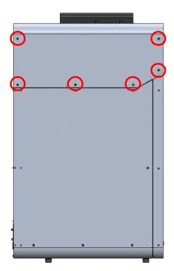
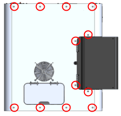
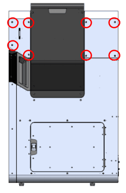
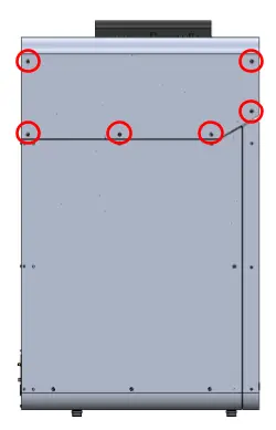
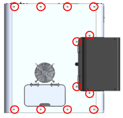
Using a 2.5 mm hex driver, remove the 26 6 mm M4 countersunk screws securing the top panel to the printer:

Remove the top enclosure panel
  • Six 6 mm screws on the front end of the buffer-side
  • 12 6 mm screws on top of the printer
  • Eight 6 mm screws on the hopper-side

Set the screws aside.

Step 2: Remove the top panel

Lift the top panel off of the printer by grabbing the IR sensor door and the rear-most edge. Set the top panel aside.

Removing the hopper-side panel and hopper shell

Overview: Remove paneling on the hopper side of the printer to access the doser assembly.

Step 1: Begin removing the hopper-side panel screws

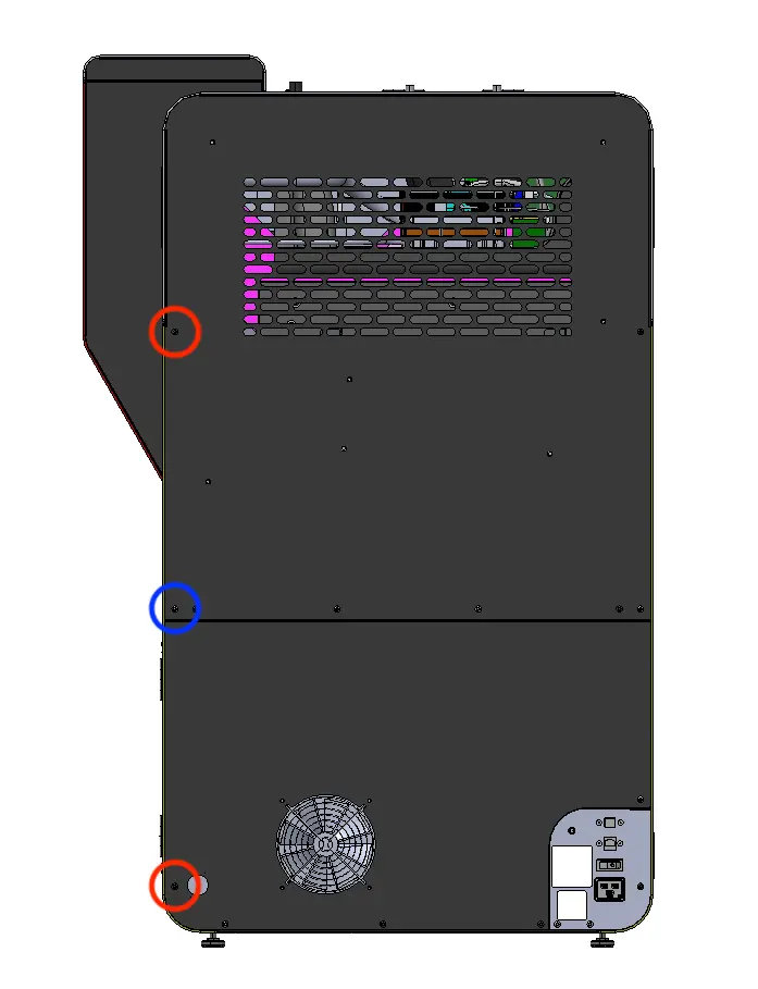
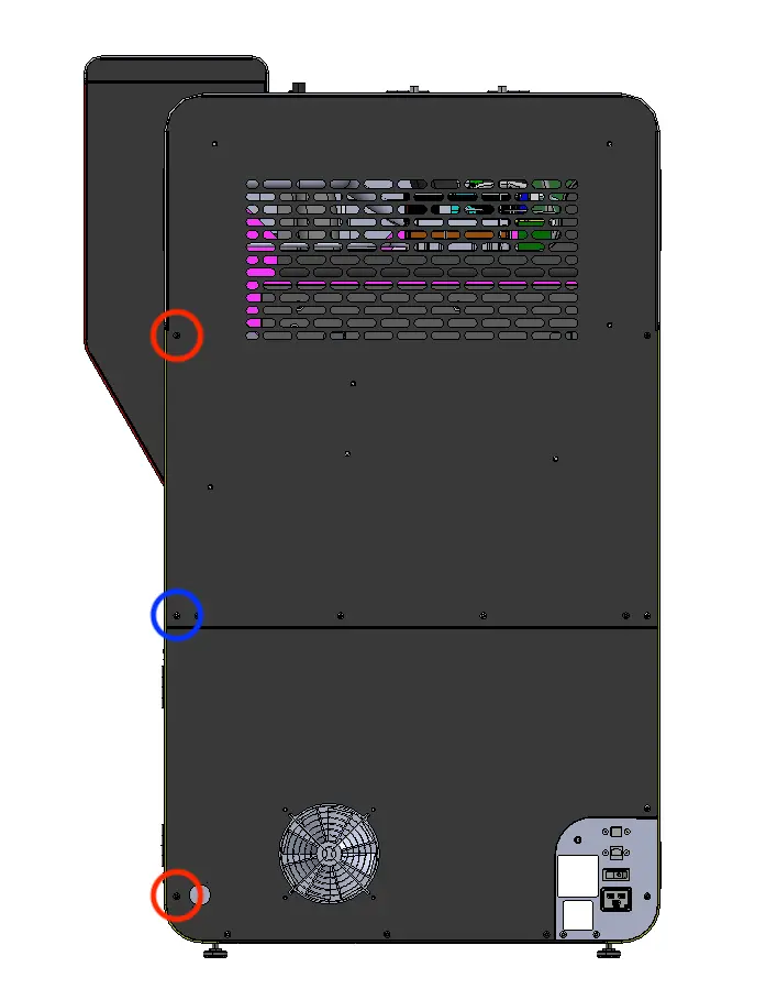
Using a 2.5 mm hex driver, loosen and remove the two black (circled in red) and one chrome (circled in blue) 8.0 mm M4 button head screws from the back-left of the printer. Take note of the locations of these screws, as the placement of the chrome screws is critical to the printer's electrical grounding. Set the screws aside.

Remove the top & hopper-side panels

Step 2: Continue removing the hopper-side panel screws

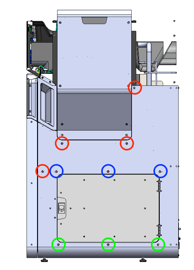
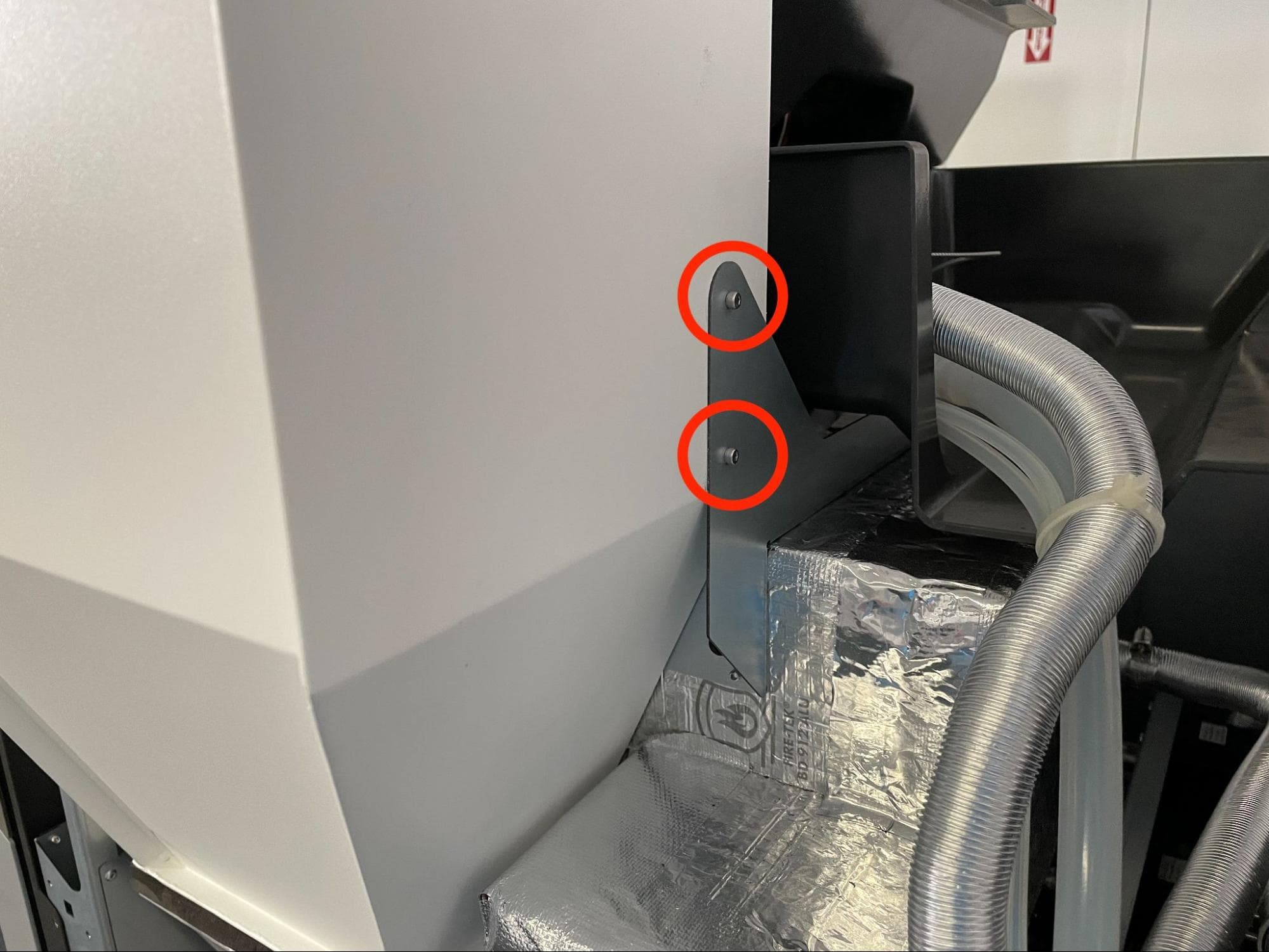
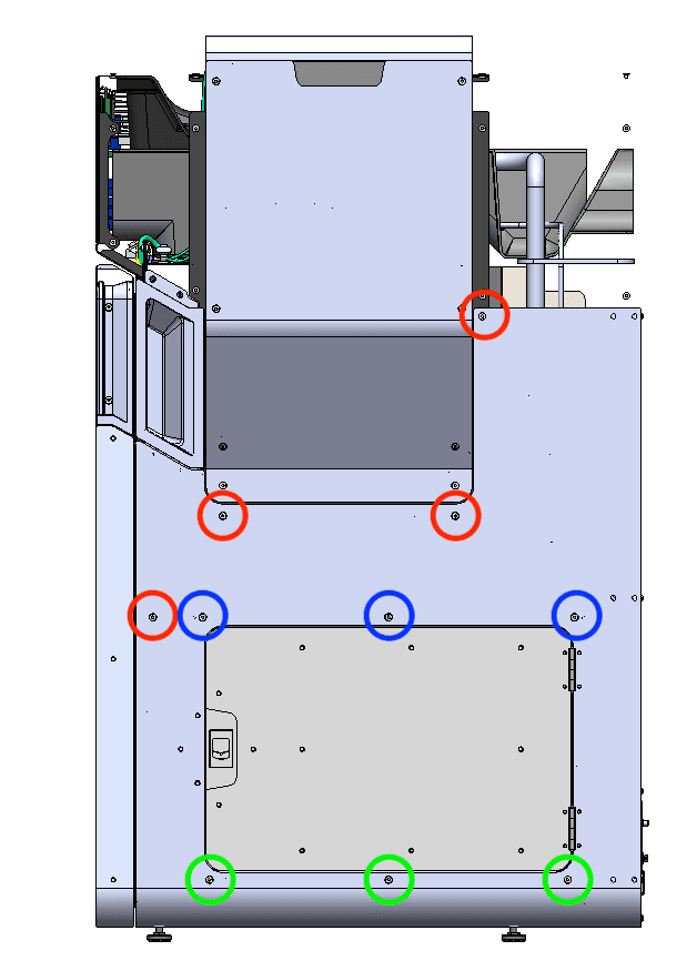
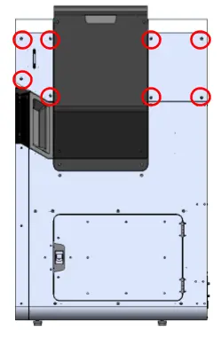
Move to the hopper side of the printer. Using a 2.5 mm hex driver, loosen and remove the 10 M4 countersunk screws holding the hopper-side panel to the printer. Remove the top-most 6.0 mm countersunk screws last to make removing the panel easier. Set the screws aside.

  • Three 16.0 mm screws, circled in green
  • Three 12.0 mm screws, circled in blue
  • Four 6.0 mm screws, circled in red
Remove the top & hopper-side panels

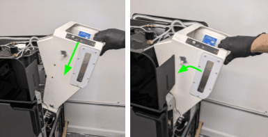
Step 3: Tilt the hopper-side panel

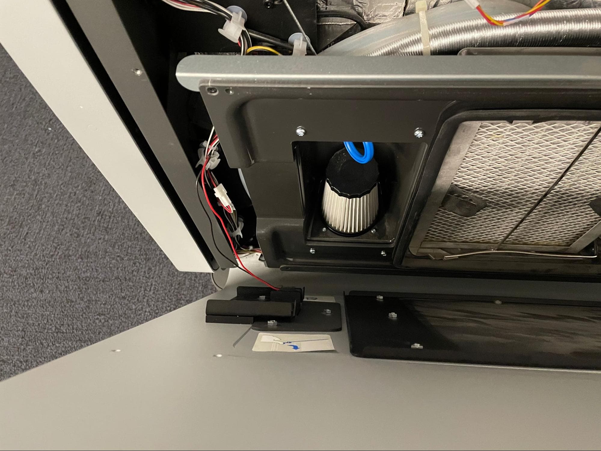
Allow the panel to tilt away from the printer, allowing access to the interlock switch cables. Do not remove the panel at this time.

Remove the top & hopper-side panels

Step 4: Disconnect the interlock switch and remove the hopper-side panel

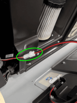
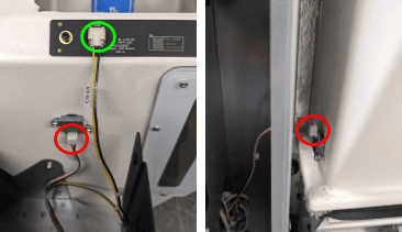
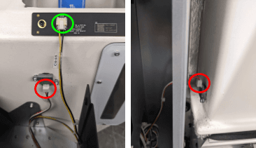
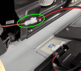
Locate the black and red cables leading to the interlock switch on the inner left-hand side of the panel. Disconnect the cable labeled C033.

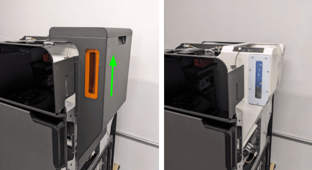
Separate the hopper-side panel from the printer, taking care to ensure that none of the cables are caught or tangled. Set the panel down on a flat, clean surface.

Remove the top & hopper-side panels

Step 5: Remove the inner door handle

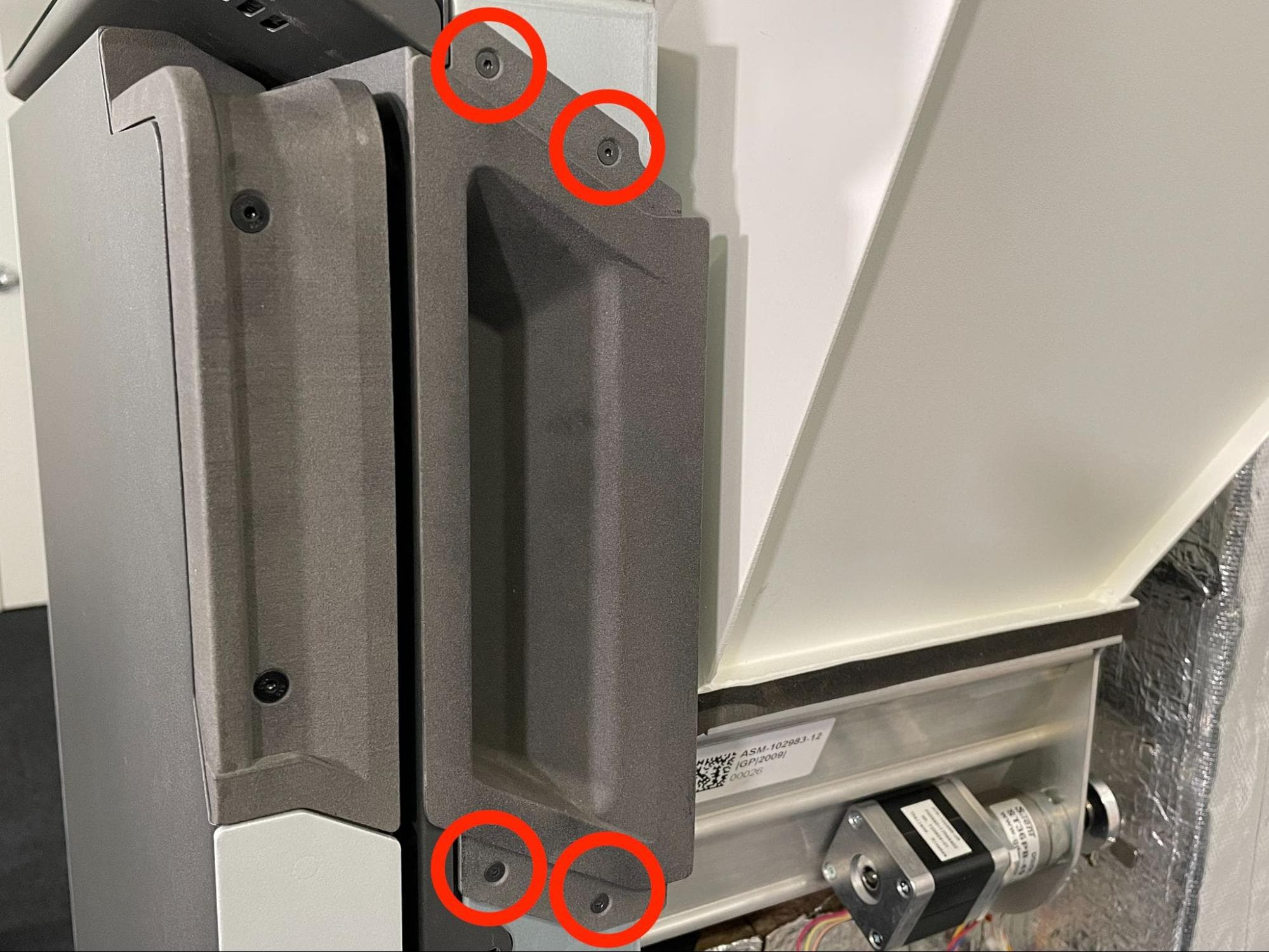
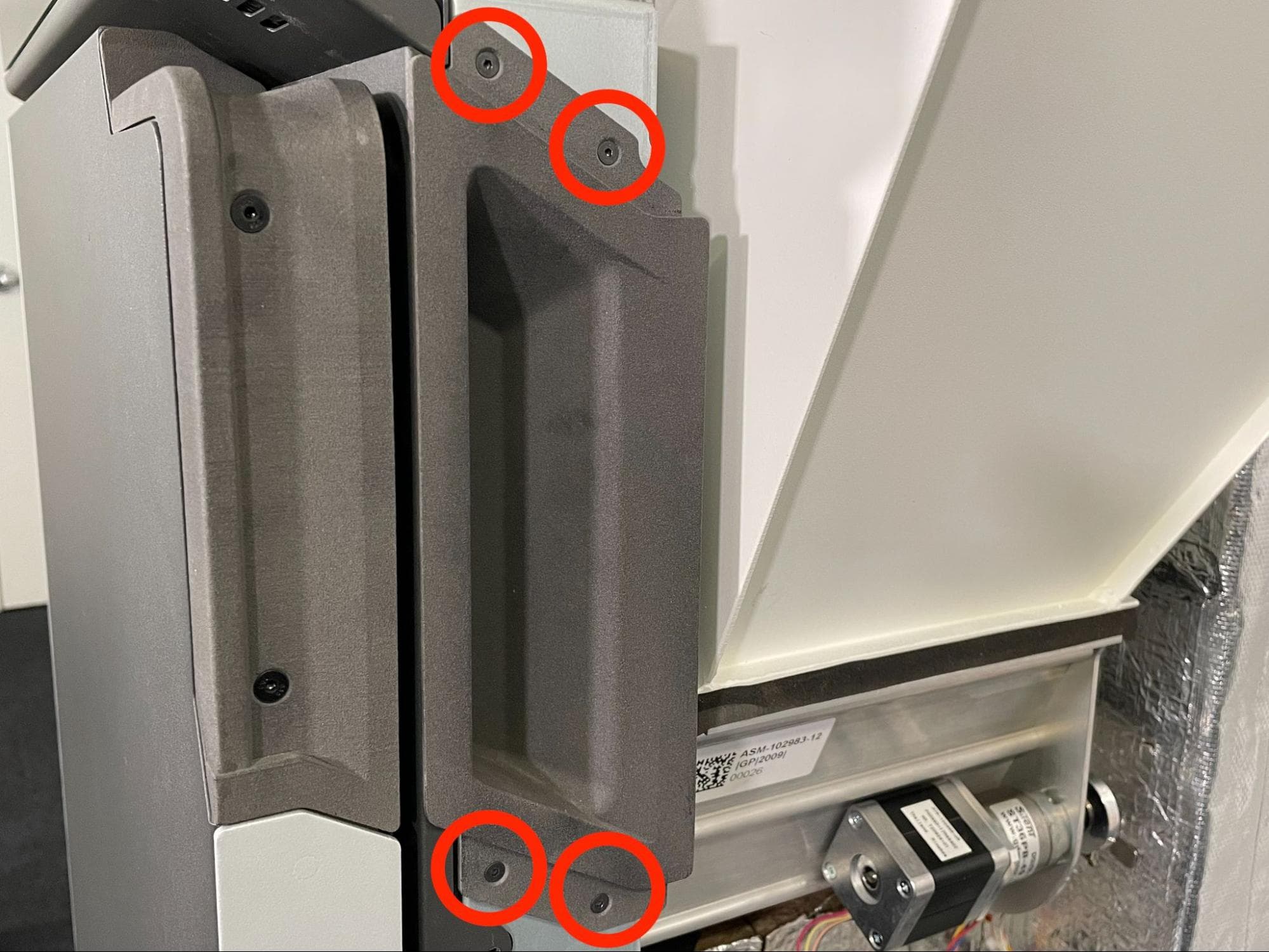
Using a 2.0 mm hex driver, loosen and remove the four 10.0 mm M3 black countersunk screws holding the inner door handle to the printer. Remove the door handle and set it and the screws aside.

Remove the top & hopper-side panels

Step 6: Remove the hopper shell

Lift the hopper shell upwards then pull it away from the printer. Set the hopper shell and lid aside

Remove the top & hopper-side panels

Removing the hopper

Overview: Remove the hopper to access the doser assembly underneath.

Step 1: Disconnect the cables from the hopper

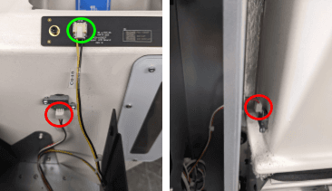
Locate and disconnect the connectors for the hopper LEDs and two powder sensors.

Remove the hopper

Step 2: Remove the hopper mounting screws

Remove the hopper
Remove the hopper

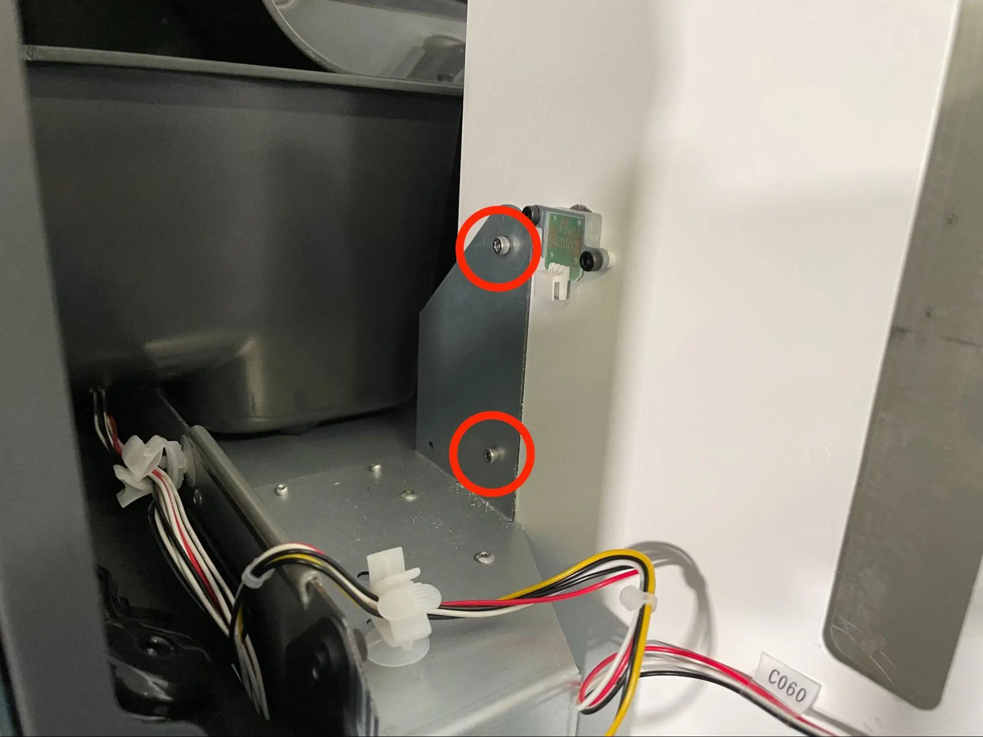
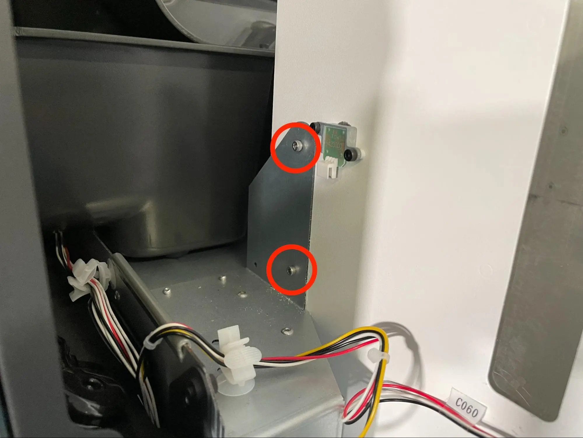
The hopper is secured to the printer using four 4 mm M3 chrome socket head screws: two on each side towards the bottom of the hopper. Using a 2.5 mm hex driver, loosen and remove the four screws. Set the screws aside.

Step 3: Remove the hopper

Tilt the hopper away from the printer and lift it off the doser.

Set the hopper down on the side opposite the window on a flat, clean surface. Do not set the hopper down on either of the gasketed ends or or the windowed side with the powder sensors, as these components may become damaged.

Remove the hopper

Removing the original doser assembly

Overview: Disconnect and remove the original doser assembly.

Step 1: Disconnect the doser cables

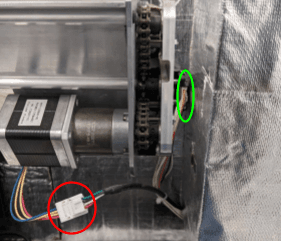
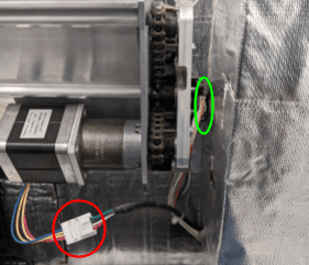
Disconnect the doser motor and encoder cables from the doser assembly.

Unplug the doser assembly cables

Step 2: Remove the doser assembly mounting screws

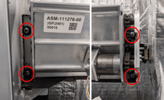
The doser assembly is secured to the printer frame by four 8 mm standoff nuts. There is a washer between each standoff nut and the doser assembly. Using an 8 mm nut driver, loosen and remove the standoff nuts. It may be helpful to use a telescoping magnet wand to catch and retrieve the washers; if they fall into the printer, they may be difficult or impossible to retrieve. Set the standoff nuts and washers aside.

If your nut driver cannot reach the nut on the top-right corner of the doser, try using an 8 mm box wrench instead.

Remove the original doser assembly

Step 3: Remove the doser assembly

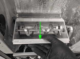
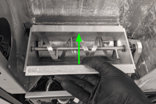
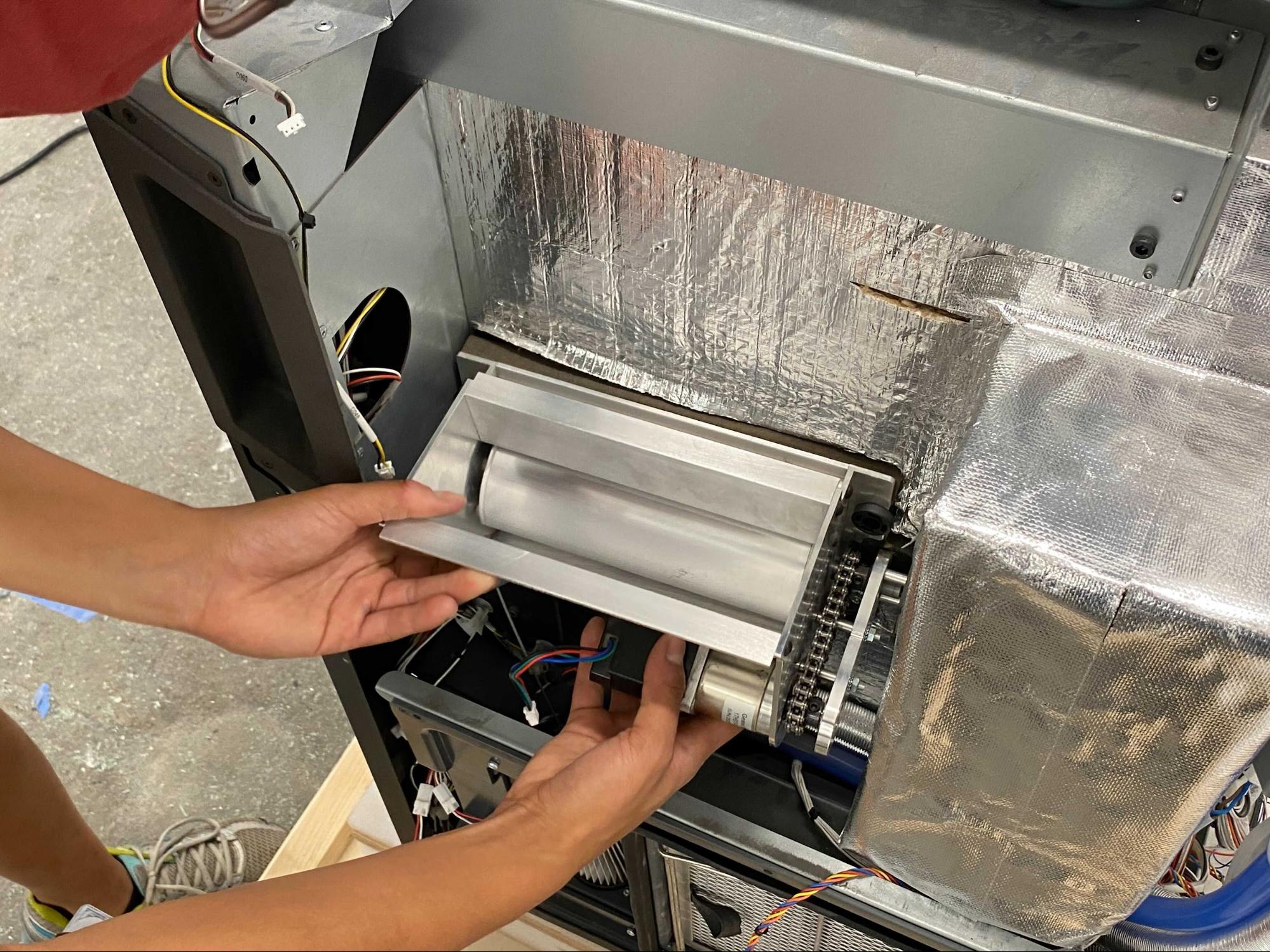
Grab the doser assembly and pull it straight back from the printer. Set it aside for disposal.

Remove the original doser assembly

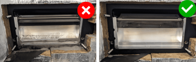
Step 4: Clean the doser interface

Vacuum any powder that remains in the interface between the doser and the printer.

Dirty doser interface

Installing the replacement doser

Overview: Connect, mount, and secure the new doser assembly.

Step 1: Mount the doser assembly

Install the new doser

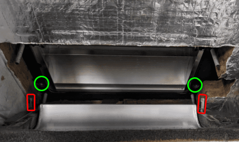
Align the two locating pins on the back of the doser assembly with the corresponding holes on the doser mounting surface. Slide the doser assembly into place until it sits flush against the printer frame.

Step 2: Secure the doser assembly

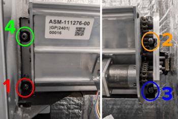
Thread the washers and standoff nuts into the four screw holes in the doser assembly. Using an 8 mm socket wrench or torque driver, torque each nut to 1.5 N-m in the sequence shown here.

Torquing the nuts out of order may lead to powder leaks. Over-torquing may strip the threaded stud, which is not repairable.

Install the new doser

Step 3: Reconnect the doser motor and encoder cables

Connect the doser motor and encoder cables to the new doser assembly.

Install the new doser

Calibrating the replacement doser

Overview: After replacing the doser assembly, calibrate its home position.

Step 1: Turn the printer on

Plug the power cable back into the rear panel then turn the printer on.

Step 2: Calibrate the doser

On the touchscreen, tap Settings > Calibration > Doser Calibration. Follow the on-screen. The printer will automatically find the correct home position for the new doser. The process typically takes up to 30 minutes to complete.

If any errors are encountered during calibration, follow any instructions provided on the touchscreen and re-run the calibration if necessary.

Step 3: Unplug the printer

Disconnect the power cable before continuing with maintenance. Do not continue performing maintenance on the printer while it is connected to power. Wait five minutes after disconnecting the printer from power before proceeding.

Reinstalling the hopper

Overview: After installing and calibrating the new doser assembly, reinstall the hopper.

Step 1: Check and clean the hopper gasket

Check that the bottom gasket of the hopper is free of debris, such as powder or pieces of insulation. Clean the gasket if necessary.

Step 2: Mount the hopper

Guide the hopper down onto the doser at a slight angle, then rotate it towards the printer. Check that the four screw holes in the hopper are aligned the corresponding screw holes in the printer frame.

Replace the hopper

Step 3: Secure the hopper

Replace the hopper
Replace the hopper

Thread one 4 mm M3 chrome socket head screw into each of the four screw holes in the hopper. Using a 2.5 mm hex driver, tighten the screws until snug.

Step 4: Reconnect the hopper cables

Reconnect the hopper LED board cable and the two powder sensor cables.

Replace the hopper

Reinstalling the hopper shell and hopper-side panel

Overview: After reinstalling the hopper, reinstall the paneling on the hopper side of the printer.

Step 1: Mount the hopper shell

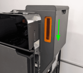
Align the hopper shell with the hopper, then slide it down into place.

Replace the top & hopper-side panels

Step 2: Mount and secure the inner door handle

Align the four screw holes in the inner door handle with the corresponding screw holes on the front edge of the hopper side of the printer. Thread one 10.0 mm M3 black countersunk screw into each of the four screw holes, then use a 2.0 mm hex driver to tighten until snug.

Replace the top & hopper-side panels

Step 3: Reconnect the interlock switch cable

Align the bottom of the hopper-side panel to the bottom of the printer and allow it to lean against you. Reconnect the interlock switch cable, labeled C033, to its receptacle. If necessary, tuck the interlock cable slack into the side of the printer’s frame.

Replace the top & hopper-side panels

Step 4: Begin securing the hopper-side panel

Thread one M4 countersunk screw into each of the 10 screw holes in the hopper-side panel. Using a 2.5 mm hex driver, tighten until snug. For greatest convenience and ease of installation, thread and tighten in the following order:

  1. Four 6.0 mm screws below the hopper, circled in red
  2. Three 16.0 mm screws below the filter door, circled in green
  3. Three 12.0 mm screws above the filter door, circled in blue
Remove the top & hopper-side panels

Step 5: Continue securing the hopper-side panel

Thread the two black 8.0 mm M4 button head screws into the screw holes circled in red in the image here. Thread the chrome 8.0 mm M4 button head screw into the screw hole circle in blue here. Using a 2.5 mm hex driver, tighten until snug.

Replace the top & hopper-side panels

Reinstalling the top panel

Overview: After reinstalling the hopper-side paneling, reinstall and secure the top panel.

Step 1: Align the top panel

Lift the top panel and place it on top of the printer. Align the screw holes in the top panel with the corresponding holes in the printer frame.

Step 2: Secure the top panel screws

Thread a 6 mm M4 countersunk screw into each of the 18 marked screw holes in the top panel:

Remove the top enclosure panel
  • Six 6 mm screws on the front end of the buffer-side
  • 12 6 mm screws on top of the printer
  • Eight 6 mm screws on the hopper-side

Using a 2.5 mm hex driver, tighten the screws until snug.

Finalizing the repair

Overview: After installing the replacement doser assembly, power on the printer and perform final checks.

Step 1: Power on the printer

Connect the power cable to the printer and the power supply. The printer initializes.

Step 2: Test the repair

Start a print. Monitor the printer to ensure that the print proceeds normally. Contact Formlabs Support or your certified service provider to share the results of the procedure.