WHITE PAPER
Formlabs Logo

Replacing the Fuse Blast blower fan

Replacing the Fuse Blast blower fan

The Fuse Blast has a blower fan that draws air from the filter cabinet out to the machine's rear exhaust. If it is faulty or malfunctioning, the Fuse Blast may run poorly, make unusual noises, or display an error such as Error 2.8.2.

Use this guide to replace the Fuse Blast blower fan.

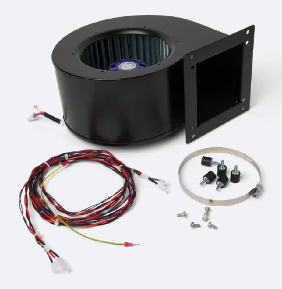
Fuse Blast blower fan

Required supplies:

Formlabs

Third-party:

  • T25 Torx driver
  • #2 Phillips driver
  • 4-2 rivets (0.125" blind rivets / .063–.125), 6x
  • Riveter tool
  • Drill and ⅛” drill bit
  • Antistatic wrist band
  • Safety glasses
  • N95 or better respirator
  • Nonreactive nitrile gloves
  • Loctite 243 or equivalent threadlocker
Warning:

The Fuse Blast is designed to contain fine particulate matter from media blasting and SLS 3D printing. Always wear an N95 respiratory mask when performing maintenance on a Fuse Blast unit.

Preparing the workspace

Overview: Prepare the Fuse Blast and a clean workspace for replacing the blower fan.

Step 1: Prepare the workspace

Clear a workspace. Ensure that the workspace is well-ventilated, level, and clean.

Step 2: Unplug the machine

Disconnect the power cable from the machine before continuing with maintenance. Do not perform maintenance on the machine while it is connected to power. Wait five minutes after disconnecting the printer from power before proceeding.

Danger:

Performing this procedure on the Fuse Blast while it is plugged in increases the risk of electric shock. Never remove any external paneling while the Fuse Blast is plugged in. Never reconnect the Fuse Blast to power while the external paneling is uninstalled.

Removing the back base panel

Overview: Remove the back base panel to access the blower fan.

Step 1: Unscrew the back base panel mounting screws

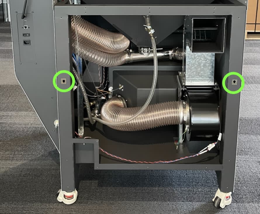
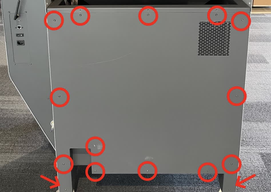
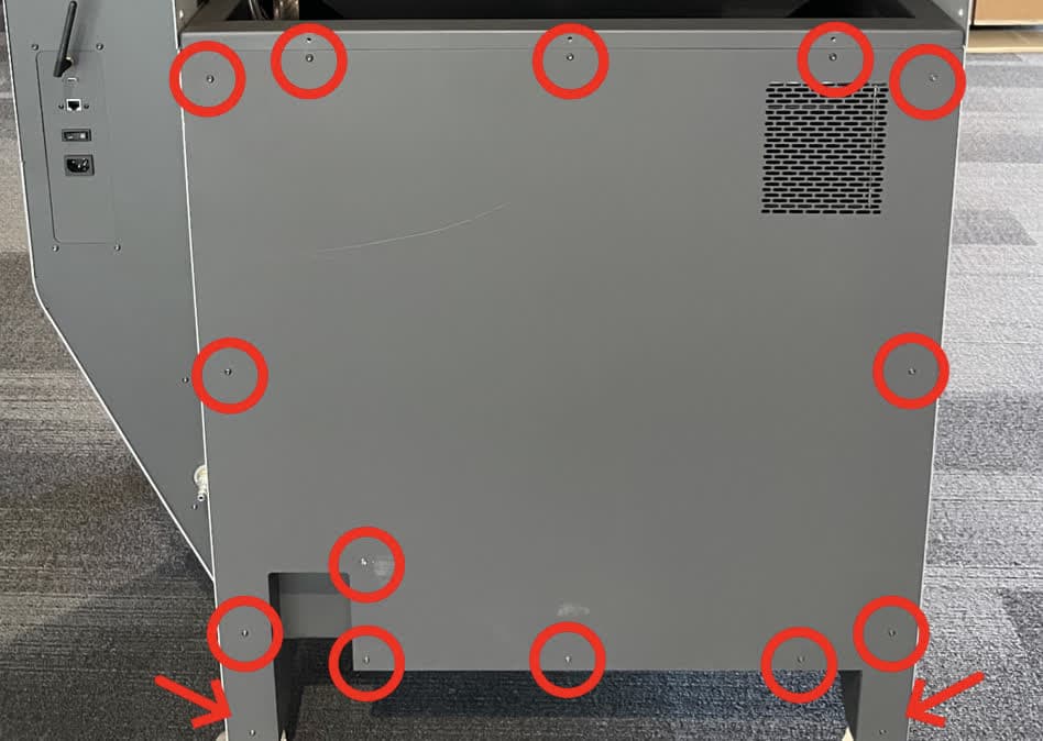
Using a T20 Torx driver, loosen and remove the 15 black oxide T20 Torx screws that secure the back base panel to the machine. Set the screws aside.

Remove the back base paanel

Step 2: Remove the back base panel

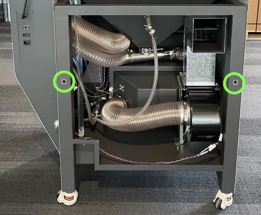
Slide the panel up to free the locating features for the panel, then remove the panel. Set the panel aside.

Remove the back base paanel

Removing the left base panel

Overview: Remove the left base panel to access the blower fan.

Step 1: Unscrew the left base panel mounting screws

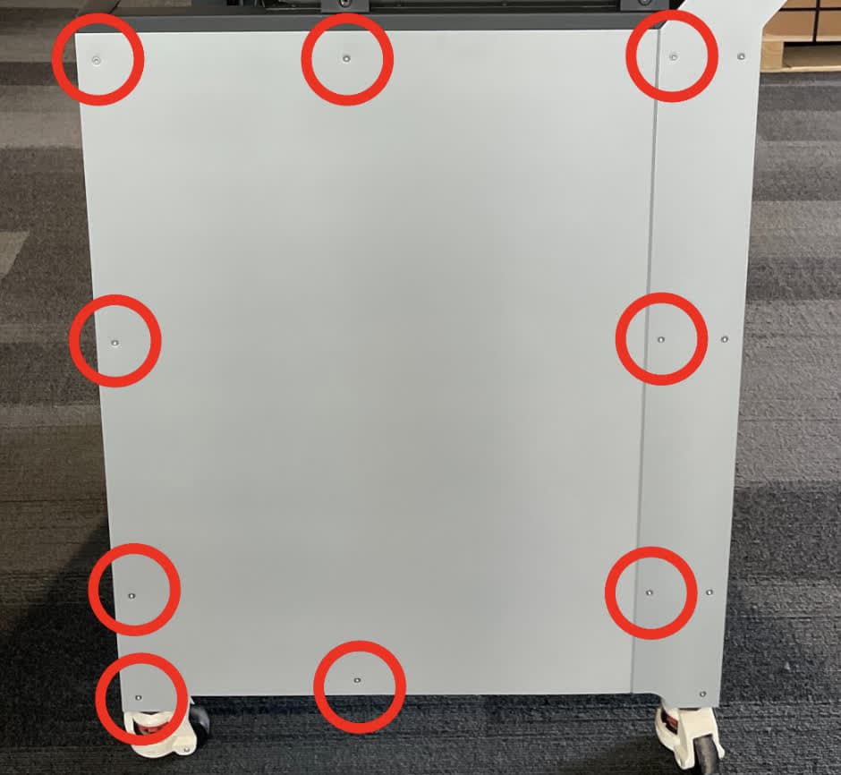
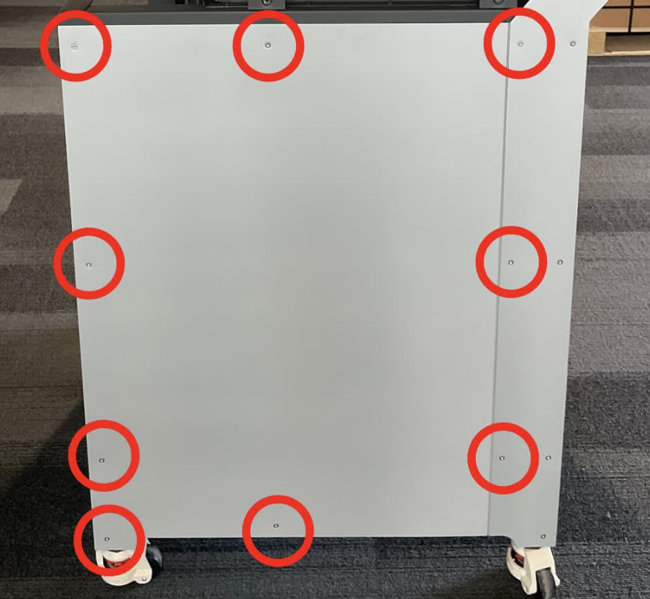
Using a T20 Torx driver, loosen and remove the nine black oxide T20 Torx screws that secure the left base panel to the machine. Set the screws aside.

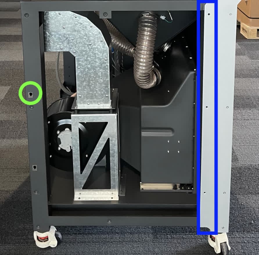
Remove the left base paanel

Step 2: Remove the left base panel

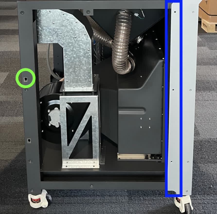
Slide the panel up to free the locating feature for the panel, then move it left to free the flange on the right. Remove the panel and set it aside.

Remove the left base paanel

Removing the original blower fan

Overview: Disconnect and remove the blower fan assembly from the Fuse Blast.

Step 1: Disconnect the blower fan cables

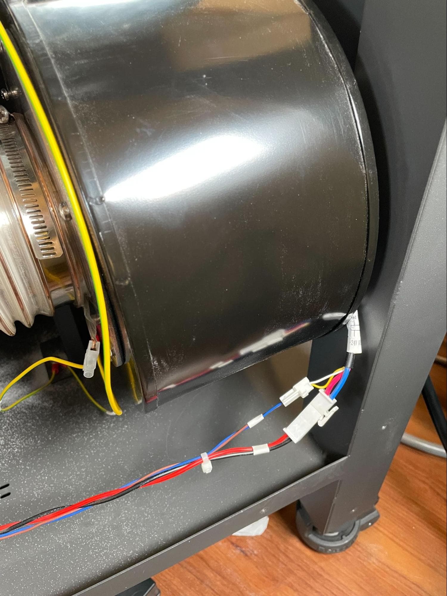
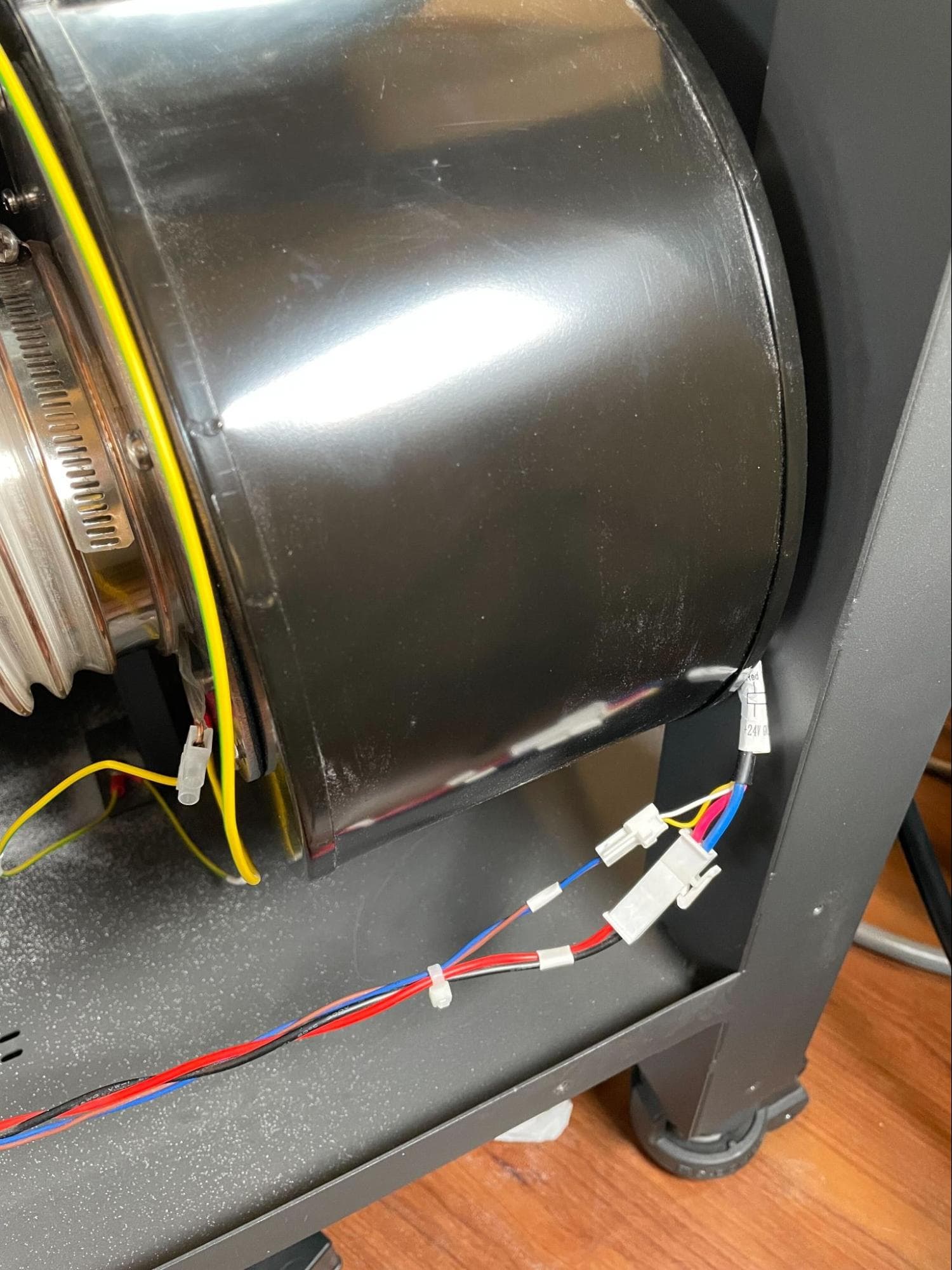
Locate the blower fan. When facing the back of the machine, the fan is positioned at the bottom-right. The blower fan has two cables connected to it. Disconnect both cables. For both, hold the connector by its plastic housing and gently squeeze the plastic locking tab. Once the plastic tab is pressed, the cable will easily slide from the connector. Do not pull on the wires themselves.

Disconnecting the Fuse Blast blower fan cables

Step 2: Disconnect the grounding wires

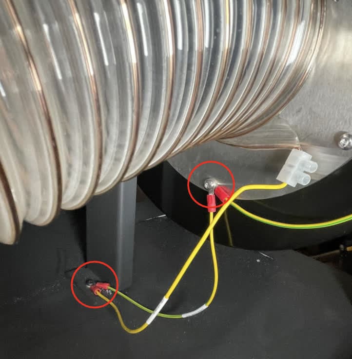
A grounding wire runs from the blower fan inlet flange (on the left side of the blower) to the frame of the Fuse Blast. Using a T20 Torx driver, loosen and remove the screws that secure the grounding wire to the blower fan and the machine. Set the screws and grounding wire aside. Note that the replacement blower fan comes packaged with a new grounding wire in case the existing one is damaged.

Disconnecting the Fuse Blast blower fan grounding wires

Step 3: Disconnect the blower fan inlet hose

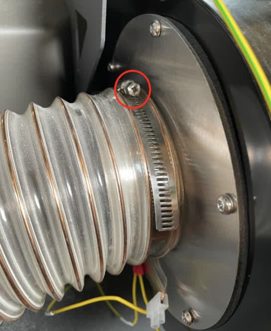
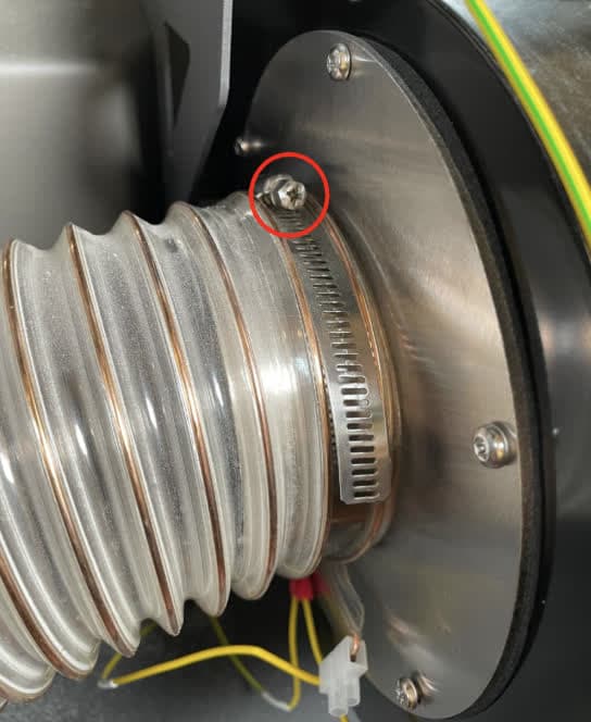
Using a #2 Phillips driver, loosen the hose clamp that secures the filter cabinet exhaust hose to the blower fan inlet. Slide the hose off of the round boss on the flange and move it out of the way of the blower fan. Note that the replacement blower fan comes packaged with a new hose clamp in case the existing one is damaged.

Disconnecting the Fuse Blast blower fan inlet hose

Step 4: Unscrew the blower fan mounting screws

Fuse Blast blower fan mounting screws

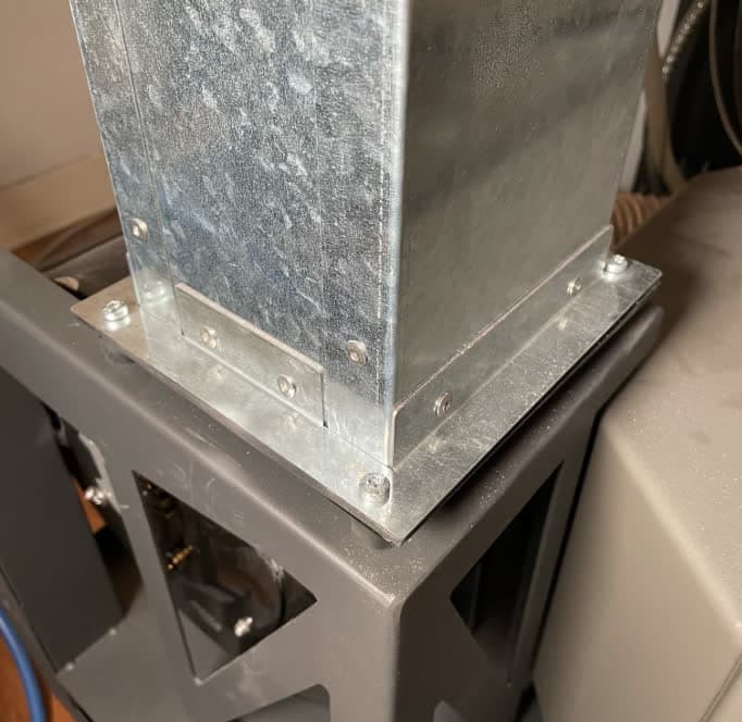
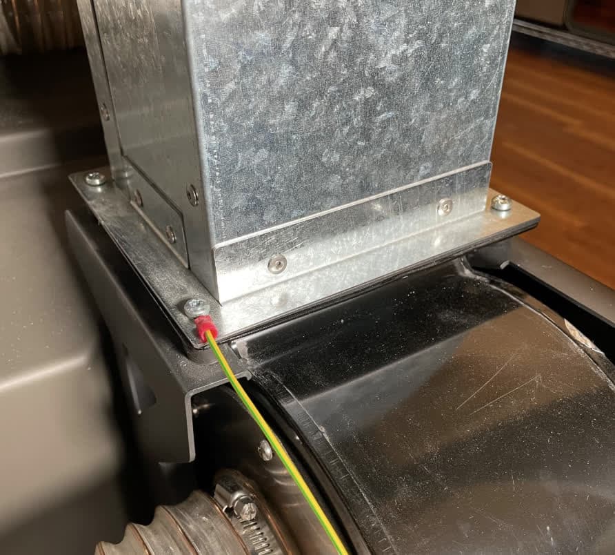
The blower fan is secured to its vibration damping mounts and the exhaust duct with four M5 screws. Using a T25 Torx driver, loosen and remove the four screws around the flange at the bottom of the exhaust duct. Note that the front-left screw also secures a grounding wire to the exhaust duct. Set the screws aside for disposal.

Step 5: Remove the blower fan

Lift the exhaust duct slightly and slide the blower fan towards yourself, off of its vibration damping mounts. Set the blower fan aside.

Step 6: Remove the vibration damping mounts

Unscrew the four vibration damping mounts from the top of the bage the blower fan was resting on. Set the vibration damping mounts aside for disposal.

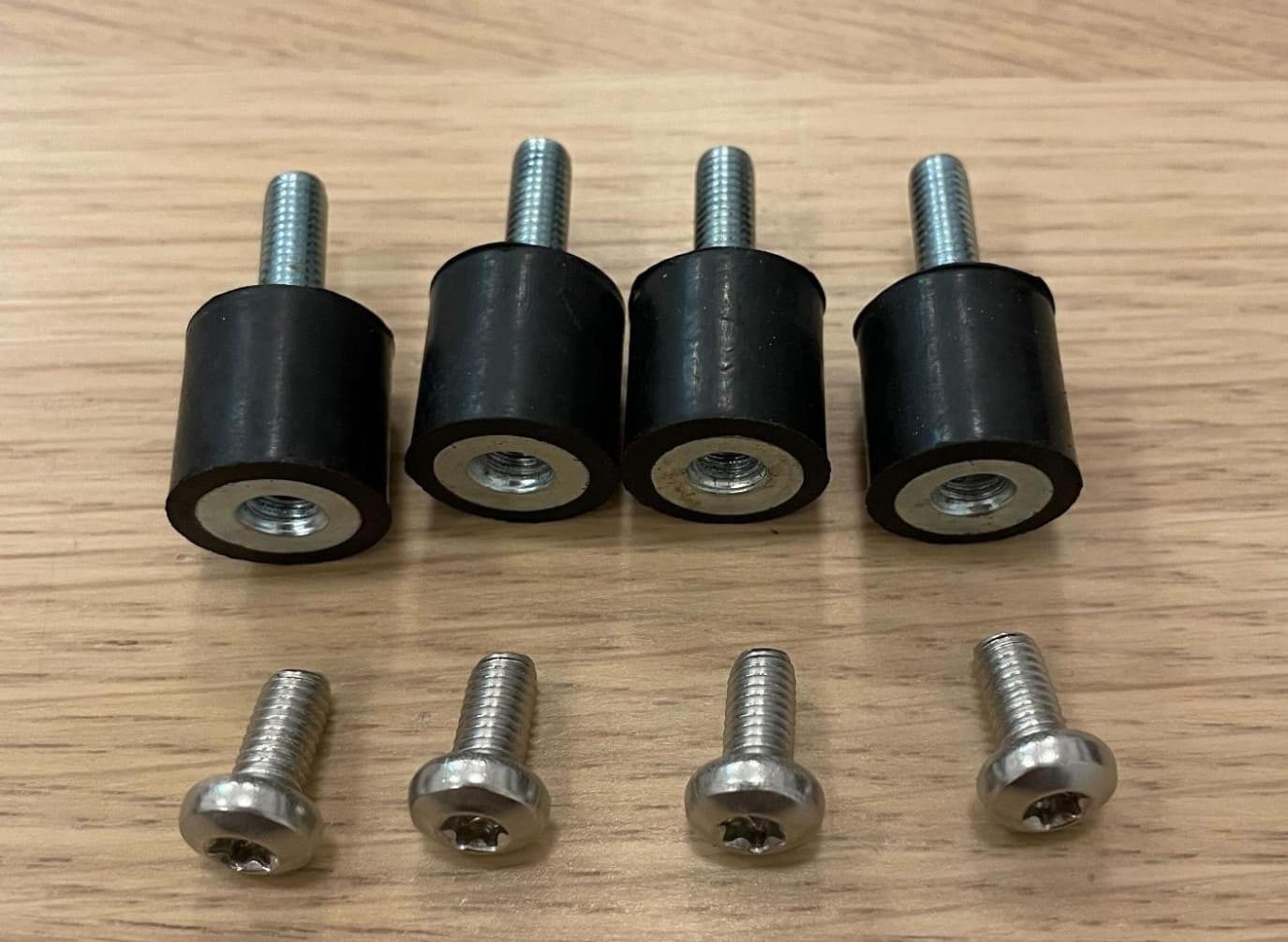
Fuse Blast blower fan fasteners

Step 7: Remove the inlet flange and gasket from the blower fan

The blower fan inlet flange and gasket will be reused on the replacement fan. Remove the flange and gasket from the blower fan inlet and set them aside. Dispose of the fan with electronic waste.

  • Fuse Blast units produced until July 2024: The flange is secured to the blower fan with six screws. Using a T20 Torx driver, loosen and remove the screws. Set the screws, flange, and gasket aside for reuse.
  • Fuse Blast units produced after July 2024: The flange is secured to the blower fan with six rivets. Use a rivet remover or drill to remove the rivets. Take care not to damage the flange. Set the flange and gasket aside for reuse.
Fuse Blast blower fan flange fasteners

Installing the replacement blower fan

Overview: Mount, secure, and connect the new blower fan.

Step 1: Mount and secure the inlet flange and gasket

Place the gasket and flange over the circular inlet hole on the side of the new blower fan. Align the six holes in the flange and gasket with the corresponding holes in the side of the fan. Secure the flange and gasket to the fan.

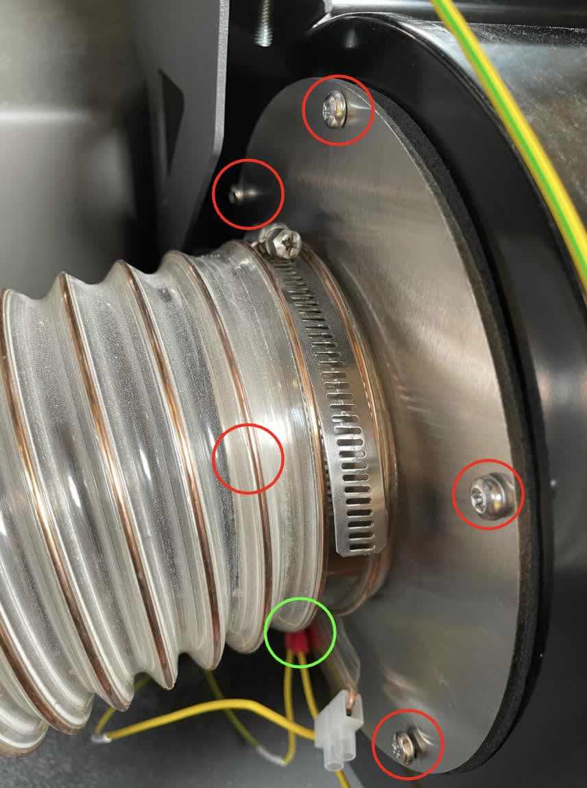
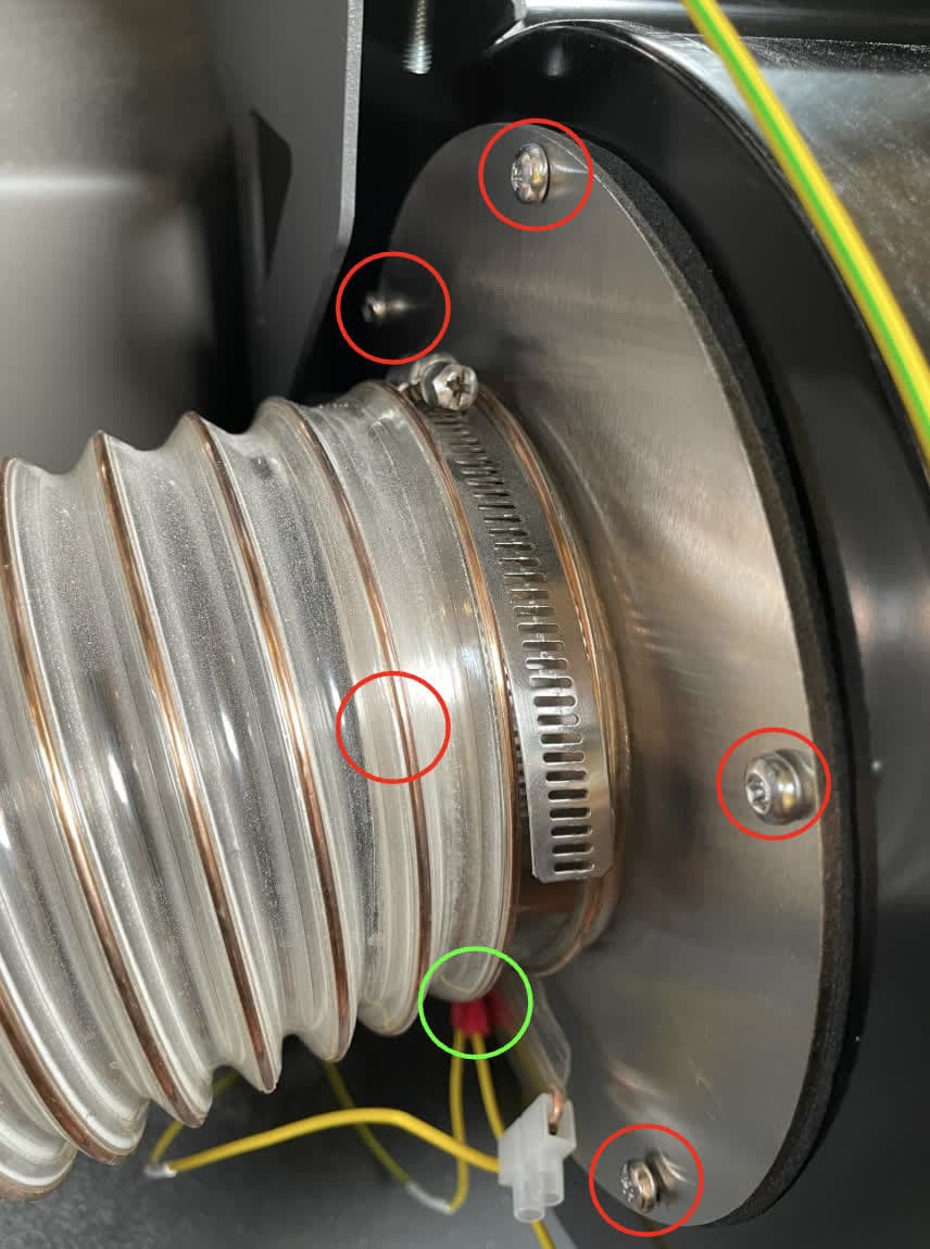
  • Fuse Blast units produced until July 2024: The flange is secured to the blower fan with six screws. Thread one screw into five of the six screw holes, leaving the bottom hole (circled here in green) empty for future installation. Using a T20 Torx driver, tighten the screws until snug.
  • Fuse Blast units produced after July 2024: The flange is secured to the blower fan with six rivets. Place one ⅛ inch/0.125" dome head blind rivet into five of the six holes, leaving the bottom hole (circled here in green) empty for future installation. Use a riveter to secure the rivets.
Fuse Blast blower fan flange fasteners

Step 2: Reconnect the blower fan grounding wire

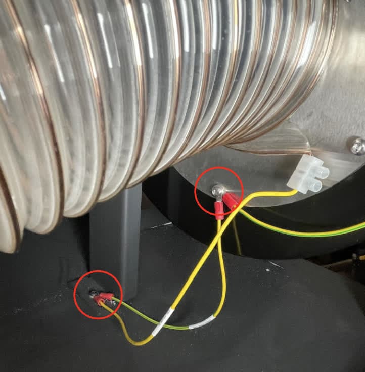
Bring the blower fan near its mount at the back of the Fuse Blast. Orient the fan with the inlet flange facing left and the rectnagular exhaust facing up. Place the grounding wire connectors over the bottom hole in the inlet flange. Use the remaining T20 Torx screw or rivet (depending on the date of manufacture of your Fuse Blast) to secure the grounding wire to the inlet flange. Secure the other end of the grounding wire to the frame of the machine using the T20 Torx screw at the bottom of the base.

Fuse Blast blower fan grounding wire

Step 3: Install the vibration damping mounts

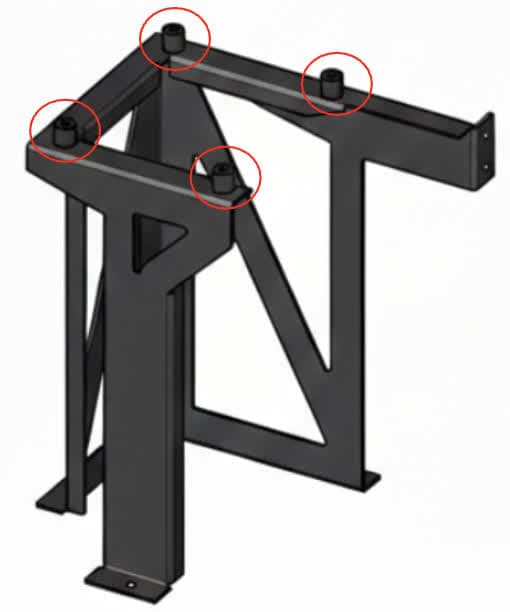
Screw one vibration damping mount into each of the four screw holes in the blower mount, under the exhaust duct. Tighten until snug.

Fuse Blast blower fan vibration damping mounts

Step 4: Mount and secure the blower fan

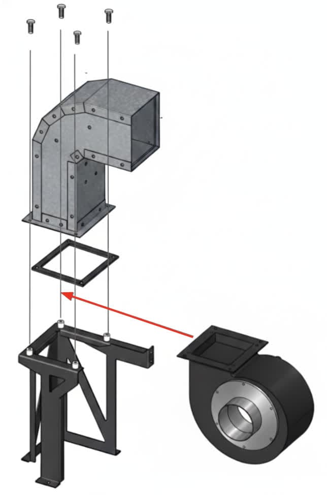
Slide the flange at the top of the blower fan between the vibration damping mounts and the bottom of the exhaust duct. Check that the screw holes in the blower fan align with the corresponding holes in the vibration damping mounts and the exhaust duct.

Apply a small dab of Loctite 243 or similar threadlocker to each of the four blower fan mounting screws. Place the remaining grounding wire connector onto the front-left screw hole in the exhaust duct flange. Thread one blower fan mounting screw into each of the four screw holes around the exhaust duct flange. Using a T25 Torx driver, tighten until snug.

Fuse Blast blower fan vibration damping mounts

Step 5: Reattach the blower fan inlet hose

Slide the filter cabinet exhaust hose to the blower fan inlet flange. Using a #2 Phillips driver, tighten the hose clamp until it is snug around the flange.

Fuse Blast blower fan inlet hose

Step 6: Connect the blower fan cables

Connect the blower fan cables to the fan. The two pairs of connectors only fit together in the correct orientation. The locking tab makes an audible click when the cables are securely connected.

Fuse Blast blower fan cables

Reinstalling the left base panel

Overview: After replacing the blower fan, mount and secure the left base panel.

Step 1: Mount the left base panel

Tuck the front edge of the left base panel under the flange towards the front of the machine. Hold the panel against the Fuse Blast frame, then slide it down to engage the locating feature. Check that the nine screw holes in the panel align with the corresponding holes in the Fuse Blast.

Remove the left base paanel

Step 2: Secure the left base panel

Thread one black oxide T20 Torx screw into each of the nine screw holes in the left base panel. Using a T20 Torx driver, tighten until snug.

Remove the left base paanel

Reinstalling the back base panel

Overview: After replacing the blower fan, mount and secure the back base panel.

Step 1: Mount the back base panel

Hold the panel against the Fuse Blast frame, then slide it down to engage the locating feature. Check that the 15 screw holes in the panel align with the corresponding holes in the Fuse Blast.

Remove the back base paanel

Step 2: Secure the back base panel

Thread one black oxide T20 Torx screw into each of the 15 screw holes in the back base panel. Using a T20 Torx driver, tighten until snug.

Remove the back base paanel

Finalizing the repair

Overview: After replacing the blower fan, power on the machine and perform final checks.

Step 1: Power on the machine

Connect the power cable to the machine and the power supply. Flip the power switch on the back of the machine to the ON position. The machine initializes.

Step 2: Test the repair

Test the various functions of the machine to ensure that it operates normally and does not make any unusual sounds.