WHITE PAPER
Formlabs Logo

Replacing the Fuse Sift doser assembly

Replacing the Fuse Sift doser assembly

The Fuse Sift doser assembly dispenses a mix of fresh and used powder from the hoppers into a powder cartridge. If the doser is faulty or malfunctioning, the Fuse Sift will be unable to dispense powder properly, leading to spills or work slowdowns.

Use this guide to replace the Fuse Sift doser assembly.

Fuse Sift doser

Required supplies:

Formlabs:

Third-party:

  • 2.5 mm hex driver (flat-end)
  • 6.5 mm slotted driver
  • 7.0 mm open-end wrench
  • Powder cartridge
  • Clean powder-safe storage containers
  • Loctite 243 or equivalent threadlocker
  • Appropriate personal protective equipment for the powder in use, as defined in the safety data sheet (SDS)
  • Compliant vacuum with static dissipative components, such as a Class II, Division 2 vacuum

Estimated time: 45–60 minutes

Preparing the workspace

Overview: Prepare the Fuse Sift and your workspace for replacing the doser assembly.

Step 1: Remove and store printed parts

Remove any printed parts from the Fuse Sift workspace to prevent them from being damaged inadvertently.

Step 2: Clean the workspace

Using the vacuum attached to your Fuse Sift, clean the workspace. Vacuum any loose powder inside the workspace, under the hood, on the print bed and the surrounding port, and on the vent filter.

Step 3: Empty the hoppers

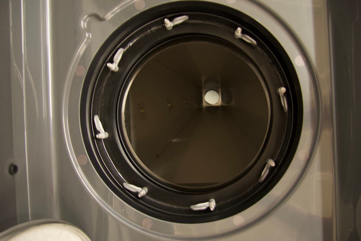
Clean used powder hopper
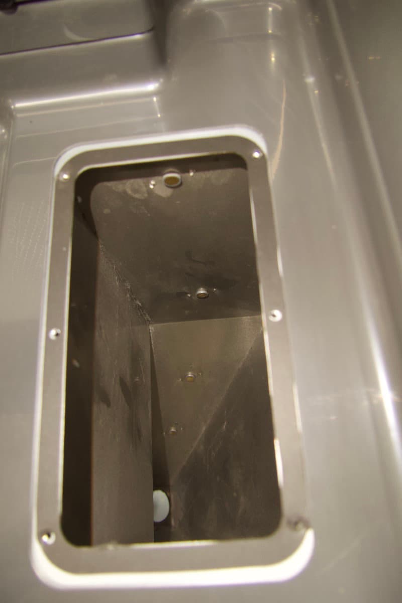
Clean fresh powder hopper

Both the fresh and used powder hoppers must be emptied before replacing the doser to prevent powder spills.

If the doser is still functional, you can empty the hoppers into one or more powder cartridges. Set the refresh rate to 100% to dispense only fresh powder, then fill an empty powder cartridge as you would normally. Similarly, set the refresh rate to 0% to dispense only used powder. Repeat until both hoppers are empty. You can transfer the powder from the cartridges to other clean containers if necessary. Label the containers to avoid contaminating your powder after you replace the doser.
If the doser is not functional, you can scoop the powder out of the hoppers from above. To access the used powder hopper, remove the surface grate and sieve. To access the fresh powder hopper, use a 2 mm hex driver to loosen and remove the four screws holding the fresh powder hopper lid in place. Set the screws and lid aside.

Step 4: Unplug the Fuse Sift

Power off the Fuse Sift, then unplug the power cable from the rear panel.

Danger:

Performing this procedure on the Fuse Sift while it is plugged in increases the risk of electric shock. After disconnecting the power from the Fuse Sift, wait at least five minutes before servicing.

Step 5: Unscrew the Wi-Fi antenna

Remove the Wi-Fi antenna, if present.

Warning:

Use appropriate personal protective equipment when handling loose or unsintered powder. Refer to the support article Safety with Formlabs SLS products or your powder’s safety data sheet (SDS) for more information.
Removing the upper front enclosure panel

Overview: Remove the upper front enclosure panel to begin accessing the doser assembly.

Step 1: Unscrew the upper front enclosure panel mounting screws

Remove the upper front enclosure panel

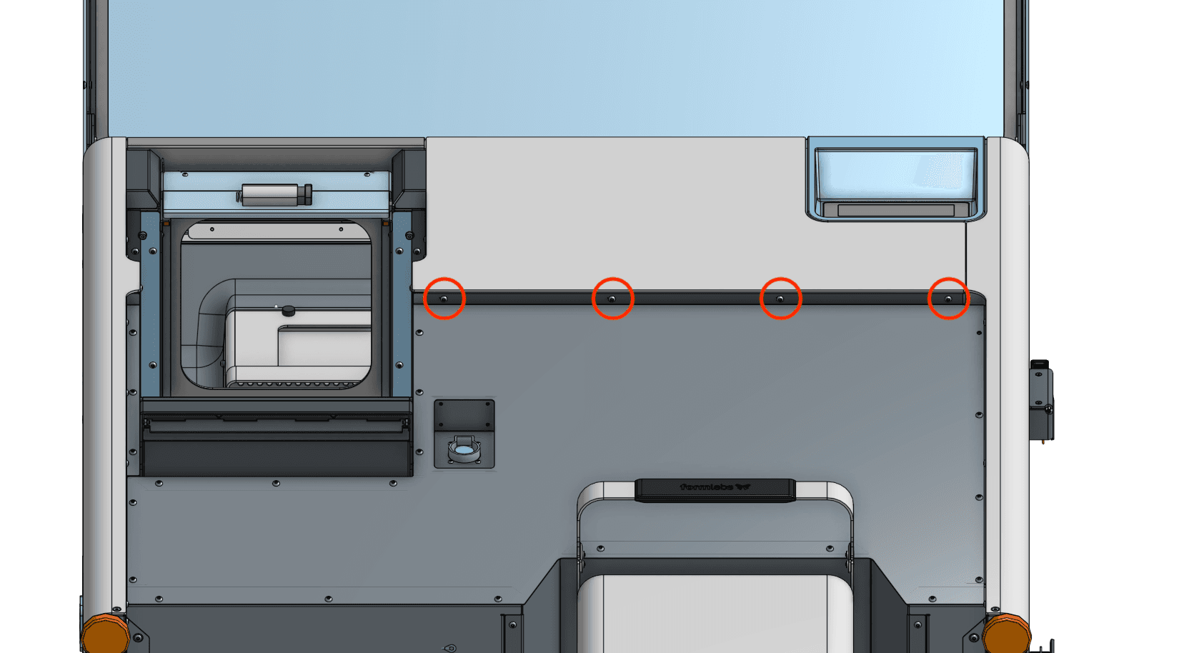
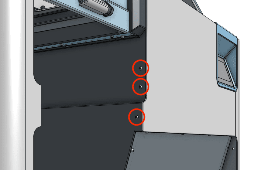
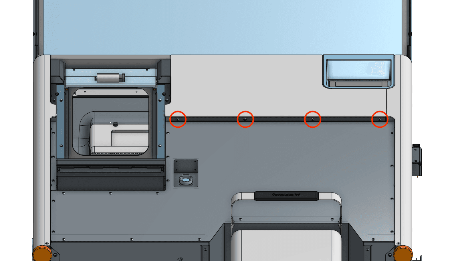
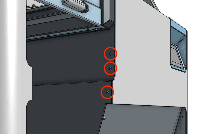
Using a 2.5 mm hex driver, loosen and remove the four black 8.0 mm M4 button screws underneath the upper front enclosure panel lip. Remove the three black 8.0 mm M4 button screws from the left-hand side of the same panel. Set the screws aside.

Step 2: Remove the upper front enclosure panel

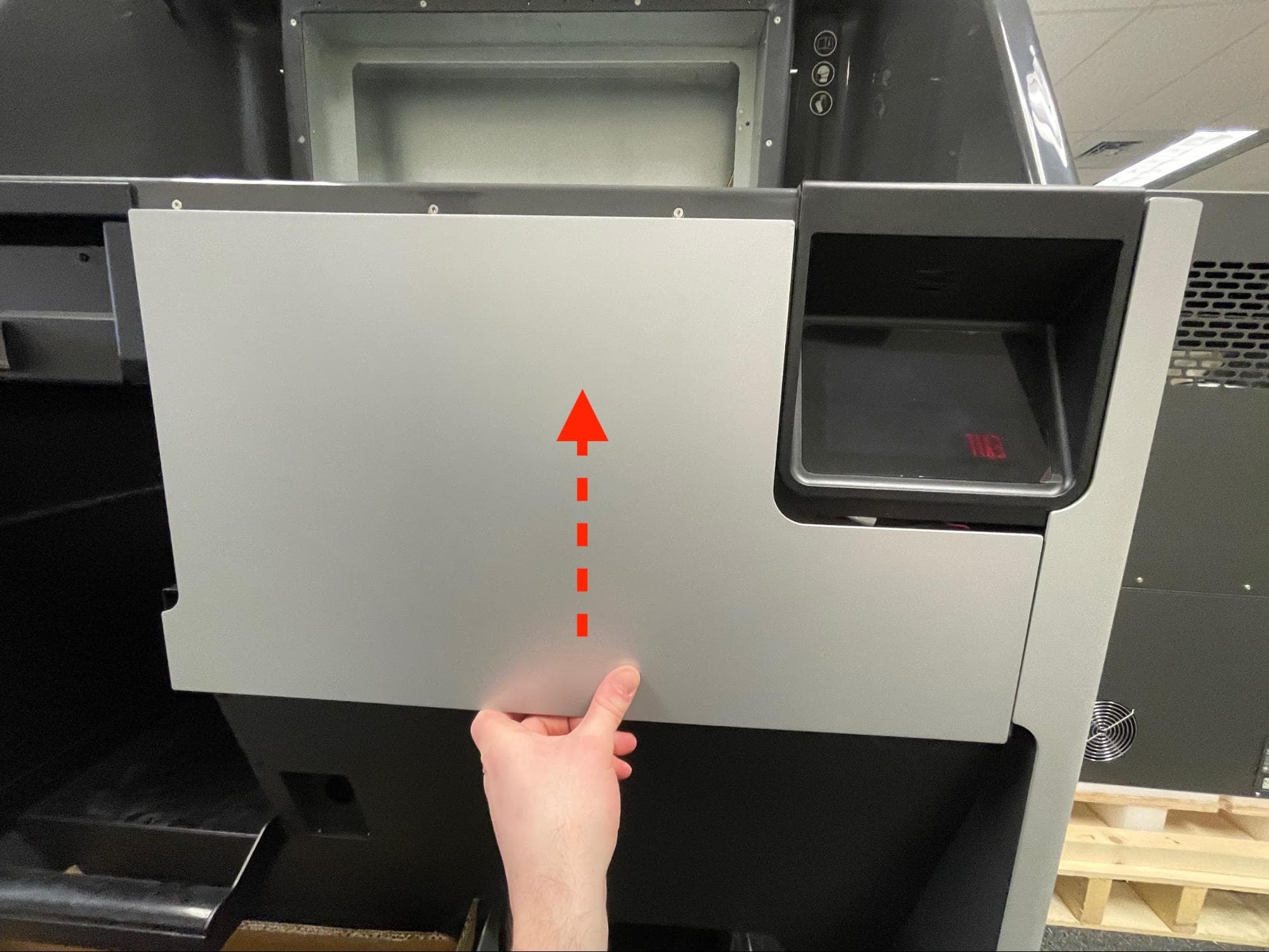
Slide the panel downwards to remove it from the Fuse Sift. Set the upper front enclosure panel aside.

Removing the lower front enclosure panel

Overview: Remove the lower front enclosure panel to access the front of the doser assembly.

Step 1: Unscrew the lower front enclosure panel mounting screws

Remove the lower front enclosure panel

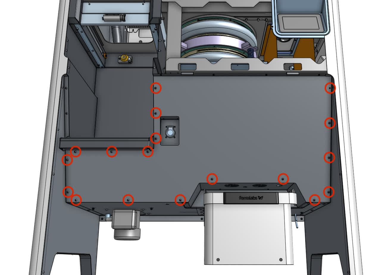
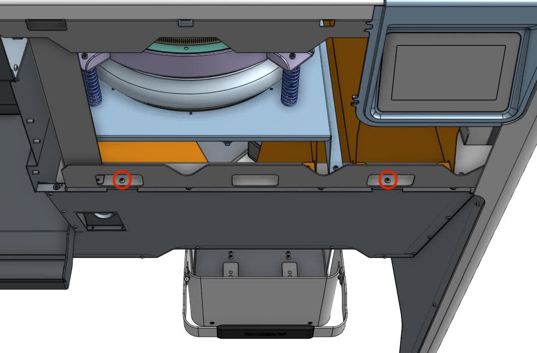
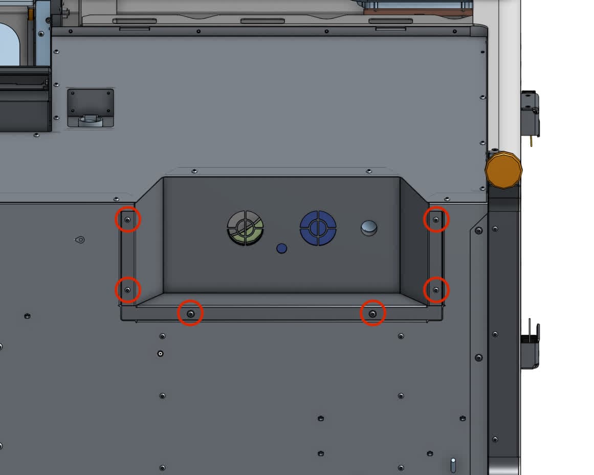
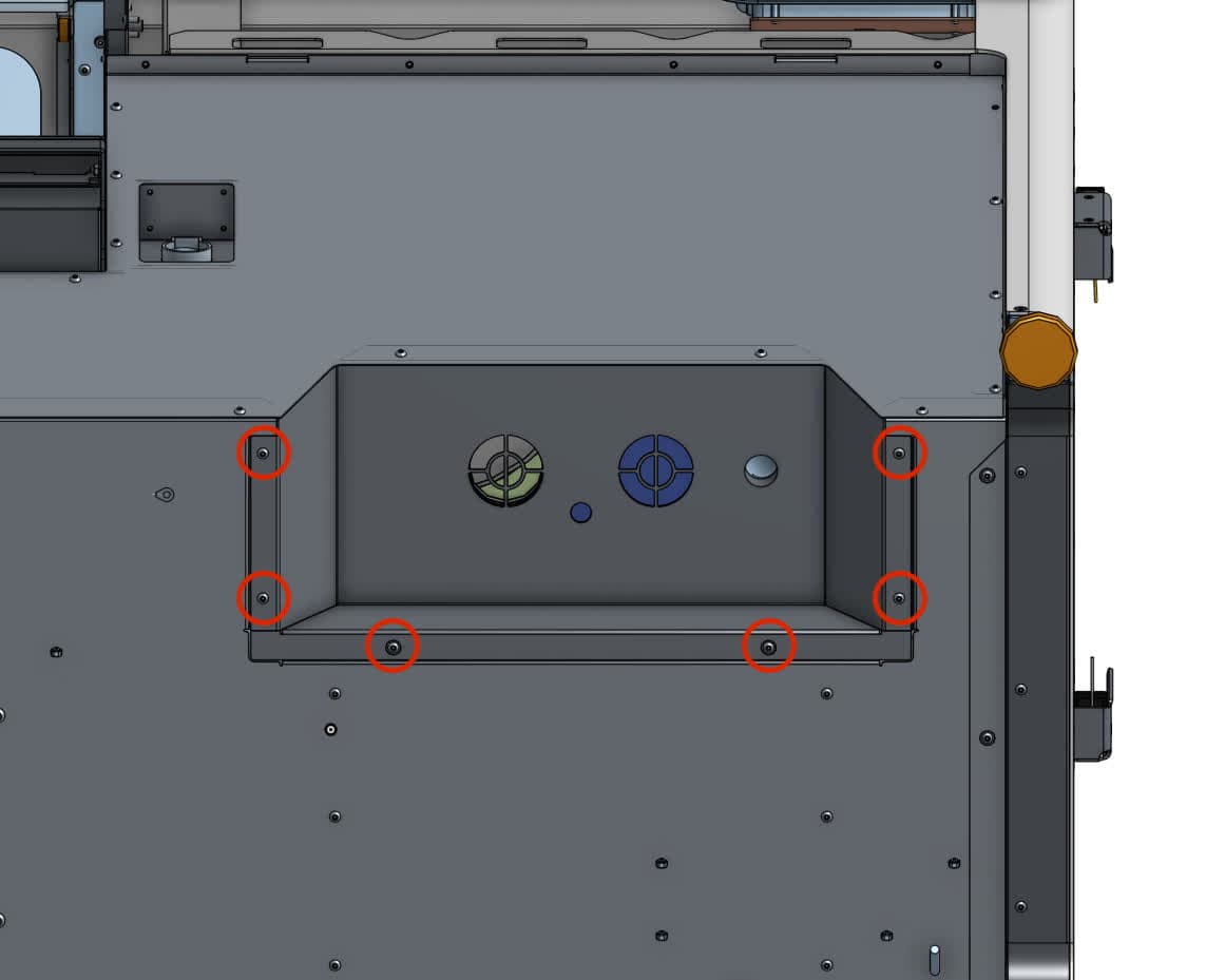
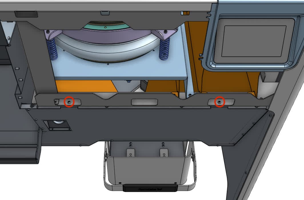
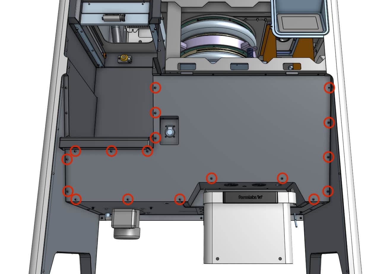
Using a 2.5 mm hex driver, loosen and remove the 18 black 8.0 mm M4 button head screws securing the lower front enclosure panel to the Fuse Sift. Remove the two chrome 8.0 mm M4 button screws holding the top of the lower panel to the inner frame. Hold the botton of the panel with one hand has you remove these screws to keep it from falling. Set all 20 screws aside.

Step 2: Remove the lower front enclosure panel.

Separate the lower front enclosure panel from the Fuse Sift. Set the panel aside.

Removing the rear enclosure panel

Overview: Separate the rear enclosure panel from the Fuse Sift in order to access the back of the doser assembly.

Step 1: Unscrew the rear enclosure panel mounting screws

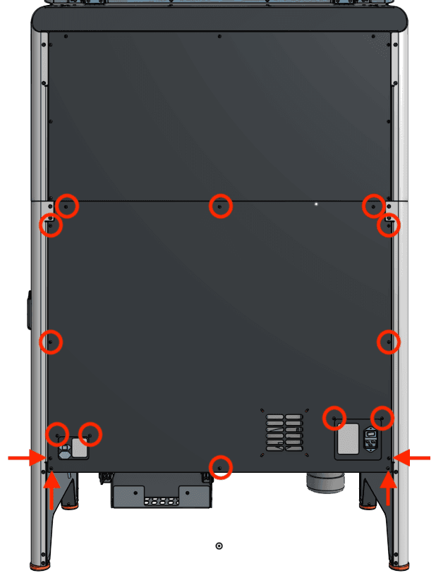
Use a 2.5 mm hex driver to remove the 16 black 8.0 mm M4 screws securing the rear panel to the Fuse Sift. Set the screws aside.

Step 2: Remove the rear closure panel

Separate the rear enclosure panel from the Fuse Sift and set it aside.

Remove the rear enclosure panel

Removing the cartridge drawer

Overview: Separate the cartridge drawer from the Fuse Sift to access the bottom of the doser assembly.

Step 1: Unscrew the cartridge drawer mounting screws

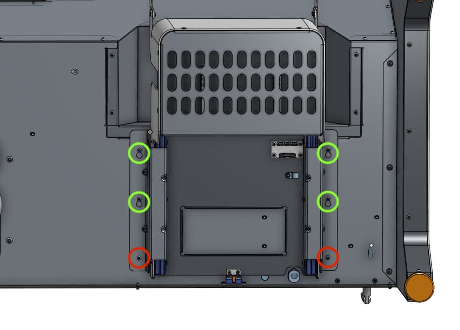
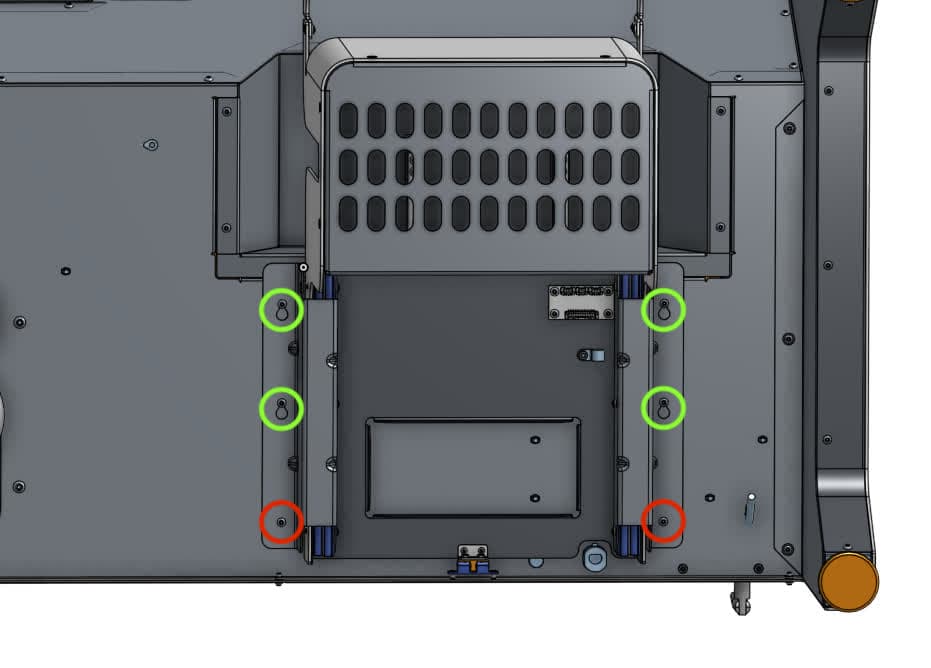
From the back of the Fuse Sift, look under the machine and locate the six 10.0 mm chrome M4 button head screws securing the cartridge drawer to the machine.

Using a 2.5 mm hex driver, loosen and remove the two screws closest to the back of the machine. Set the screws aside. Loosen the remaining four screws but do not remove them.

Remove the cartridge drawer

Step 2: Separate the cartridge drawer from the Fuse Sift

Remove the cartridge drawer

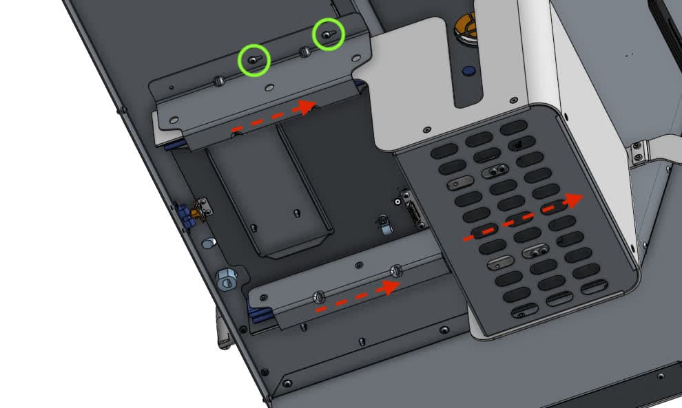
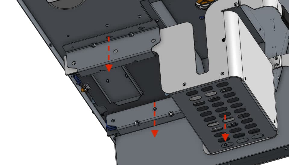
Grab both rails and slide the entire cartridge drawer assembly forward towards the front of the machine until the remaining screws clear the drawer flange mounting slots.

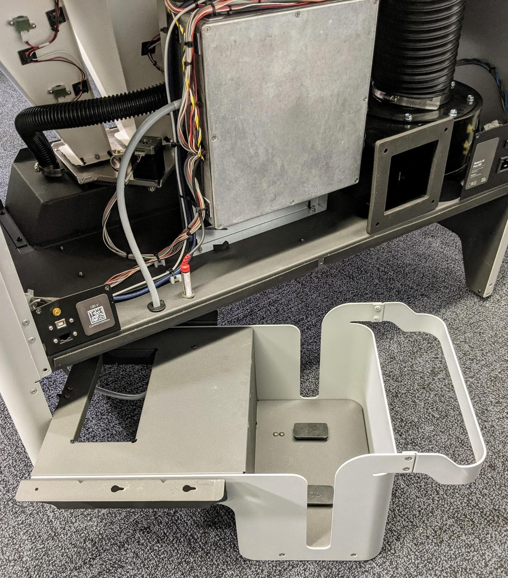
Carefully set the cartridge drawer assembly down below the machine. Do not strain or damage the cables that still connect the drawer to the Fuse Sift.

Caution:

The drawer slides can now move freely and may pose a pinching hazard.

Removing the doser assembly

Overview: Disconnect and remove the original doser assembly.

Step 1: Disconnect the doser cables

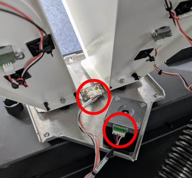
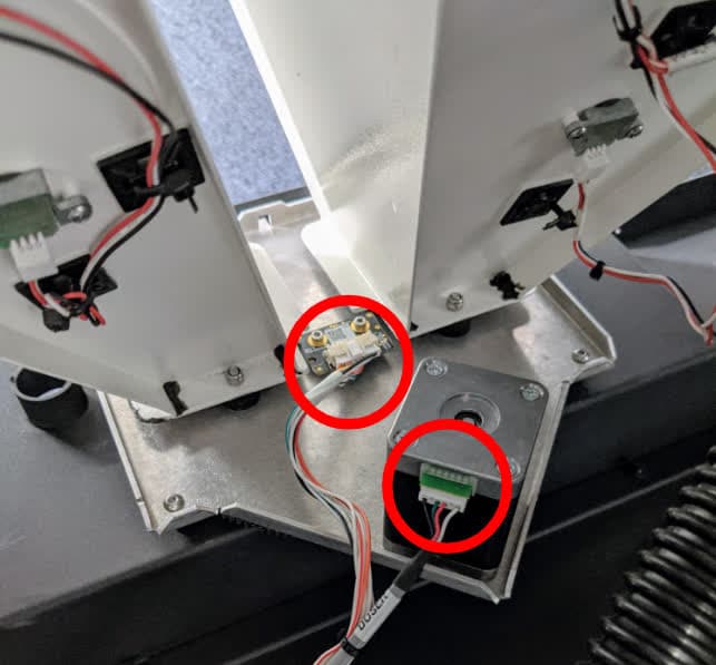
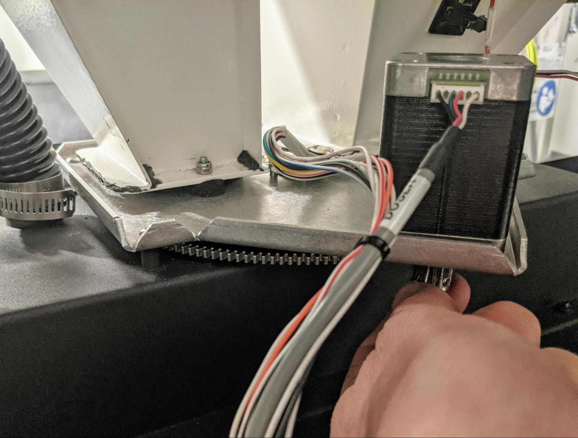
Disconnect the doser motor and encoder cables from the doser assembly. The encoder cable has a locking tab that must be squeezed before it can be unplugged. Be sure to pull on the plastic connectors, not the wires themselves.

Remove the original doser assembly

Step 2: Clean the doser assembly

Disconnect the vacuum hose and power cable from the Fuse Sift and connect it to a power source. Use the vacuum to clean the powder around the entire doser assembly. Reconnect the vacuum to the Fuse Sift when you are done.

Step 3: Disconnect the doser vacuum hose

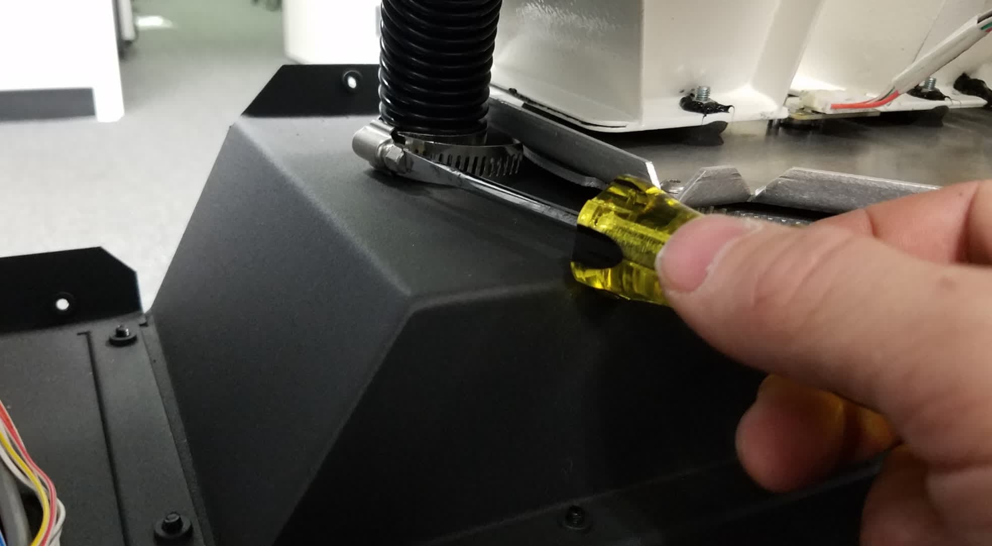
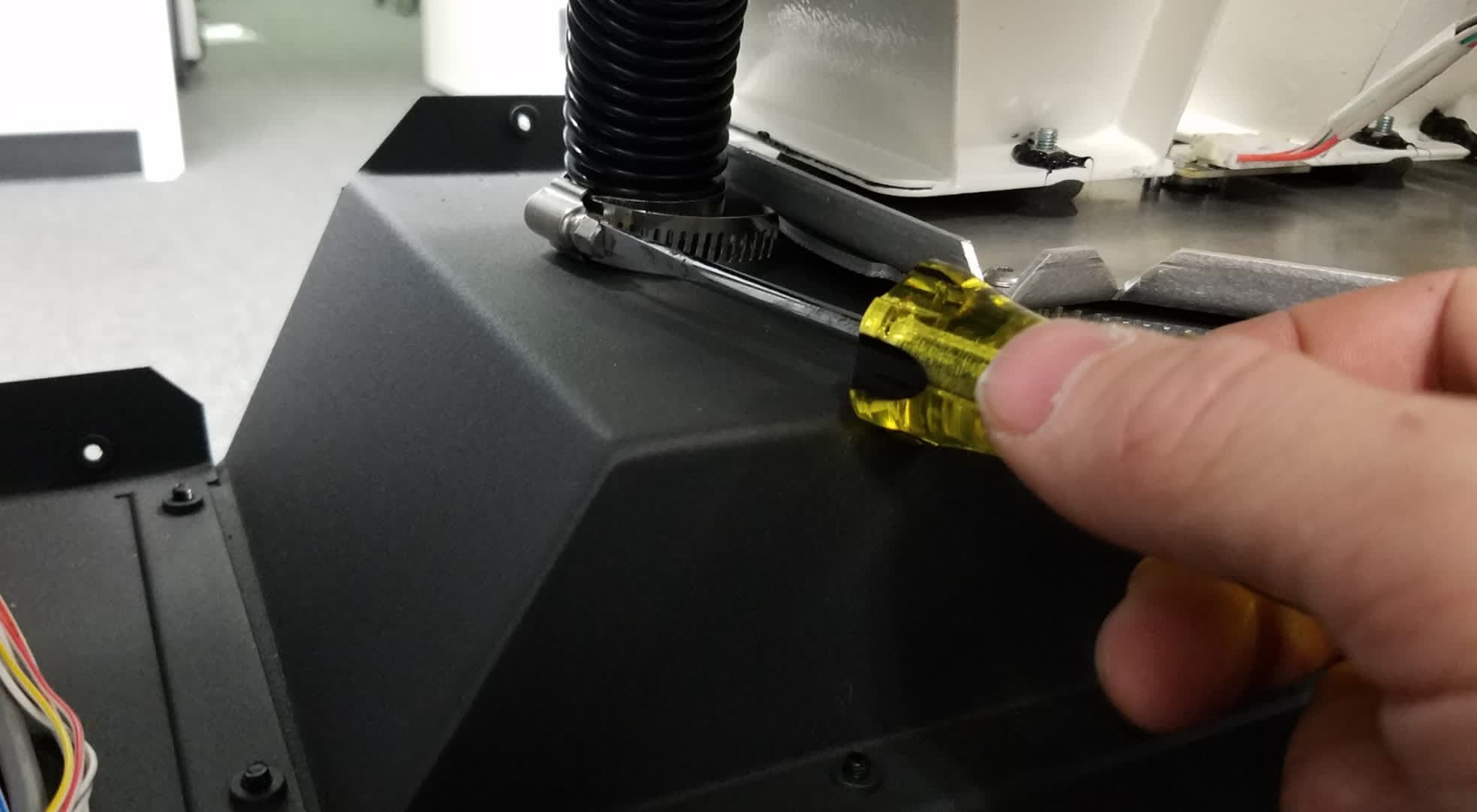
From the rear of the machine, use a 7.5 mm slotted screwdriver to loosen the clamp securing the vacuum hose to the top of the doser assembly. Detach the hose from the doser assembly.

Remove the original doser assembly

Step 4: Disconnect the hoppers from the doser

Using a 7.0 mm wrench, loosen and remove the four M4 nuts securing the hoppers to the doser assembly. The hoppers have two nuts each: one in the front and one in the back.

Remove the original doser assembly

Step 5: Remove the doser assembly

Remove the original doser assembly

From the front of the machine, locate the doser assembly immediately above where the cartridge drawer was installed. Support the doser assembly and use a 2.5 mm hex driver to loosen and remove the six black 10.0 mm M4 button head screws securing the doser assembly to the machine.

Set the screws aside. Set the doser aside for disposal with electronic waste.

Installing the replacement doser assembly

Overview: Mount, secure, and connect the replacement doser assembly.

Step 1: Mount the diser assembly

Orient the new doser assembly with the motor facing up and away from you. Lift the new doser assembly up into position from the front of the Fuse Sift.

Install the new doser assembly

Step 2: Secure the doser assembly

Apply a small dab of Loctite 243 or equivalent threadlocker to the threads of the six black 8.0 mm M4 button head screws that secure the doser to the Fuse Sift. Thread one of the screws into each of the six screw holes around the edge of the doser assembly. Using a 2.5 mm hex driver, tighten the screws until snug.

Install the new doser assembly

Step 3: Connect the hoppers to the doser assembly

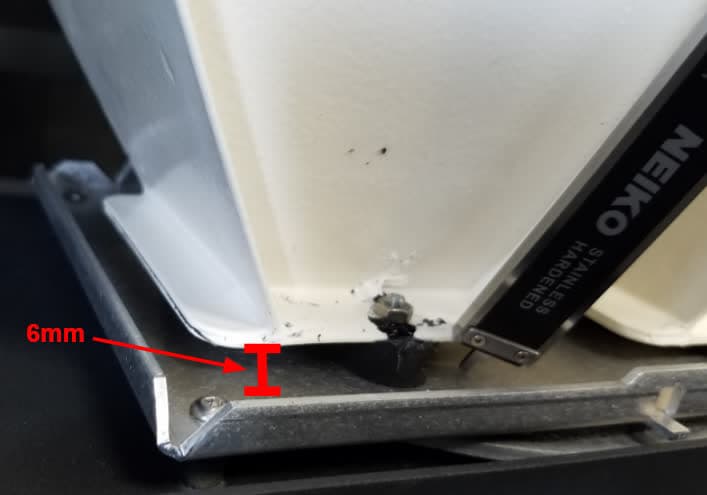
Thread one nut onto each of the four threaded posts extending up through the bottom of the two hoppers. Using a 7.0 mm wrench, tighten the nuts until there is a 6.0 mm gap between the hoppers and the doser assembly plate.

Install the new doser assembly

Step 4: Connect the doser assembly cables

Connect the doser motor and encoder cables to the new doser assembly. Ensure that the encoder cable locking tab clicks into place.

Install the new doser assembly

Step 5: Connect the vacuum hose to the doser assembly

Slide the vacuum hose onto the port on the top of the doser assembly, then tighten the hose clamp with a 6.5 mm slotted screwdriver.

Reinstalling the cartridge drawer

Overview: After replacing the doser assembly, mount and secure the cartridge drawer.

Step 1: Mount the cartridge drawer

Mount the cartridge drawer

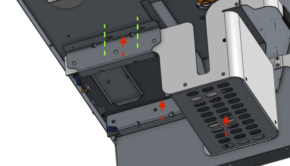
From the back of the machine, guide the drawer assembly upward onto the underside of the machine so the four mounting slots align with the remaining four chrome 10.0 mm M4 button screws.

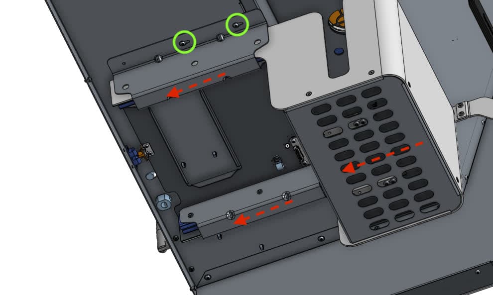
Grab both rails to slide the entire drawer backward towards the back of the machine until the screws engage all four drawer flange mounting slots.

Step 2: Secure the cartridge drawer

Apply a small dab of Loctite 243 or equivalent threadlocker onto both of the remaining chrome 10.0 mm M4 cartridge drawer mounting screw. Thread one screw into both of the remaining screw holes in the cartridge drawer flanges. Using a 2.5 mm hex driver, tighten all six screws until snug.

Secure the cartridge drawer

Verifying the doser position

Overview: After reinstalling the cartridge drawer, check the position of the doser and correct it if needed.

Step 1: Locate the doser gear alignment tabs

Verify the doser position

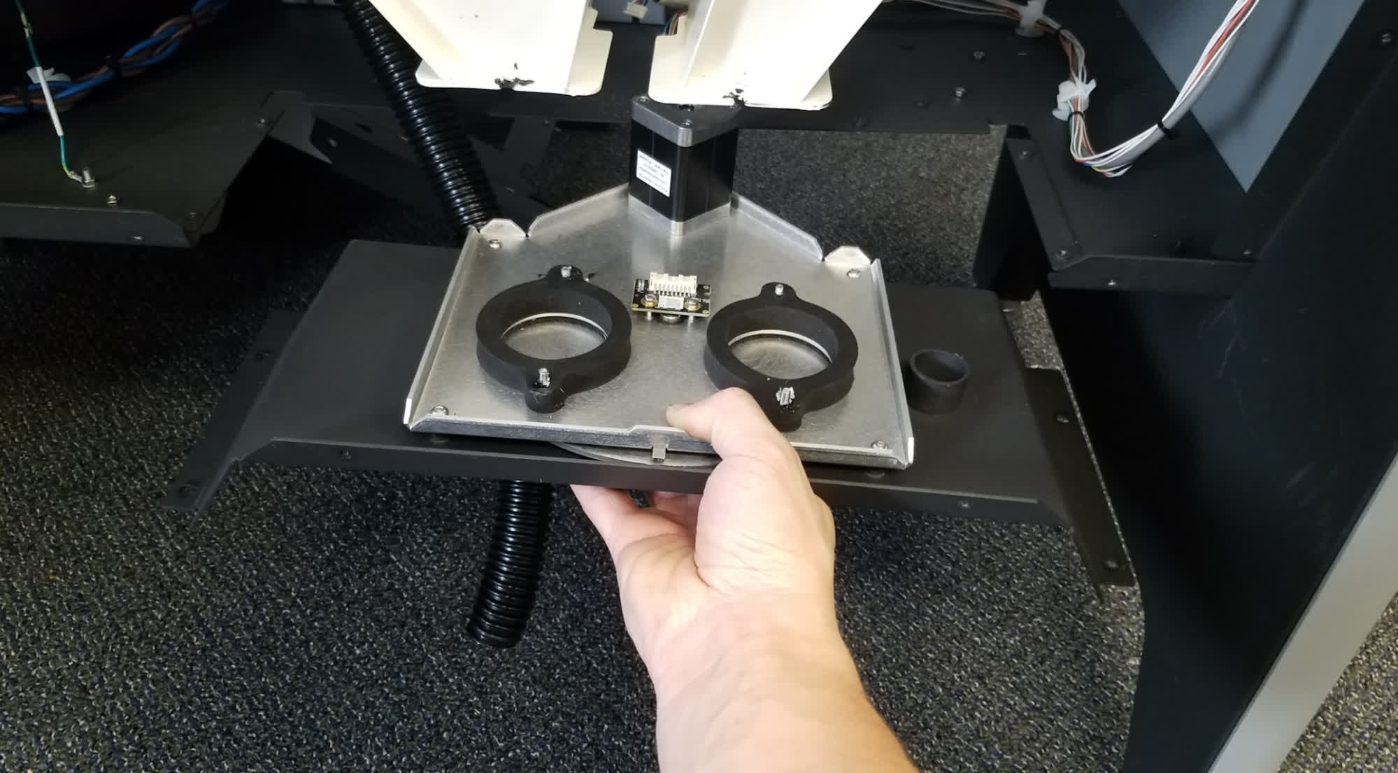
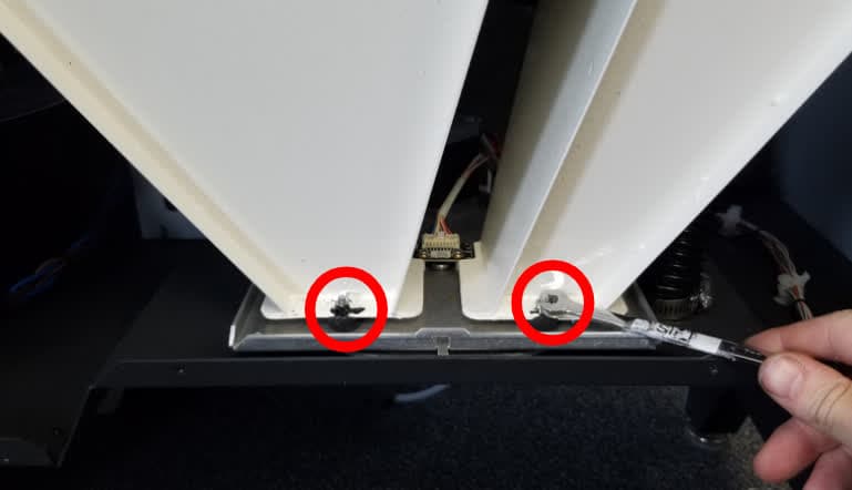
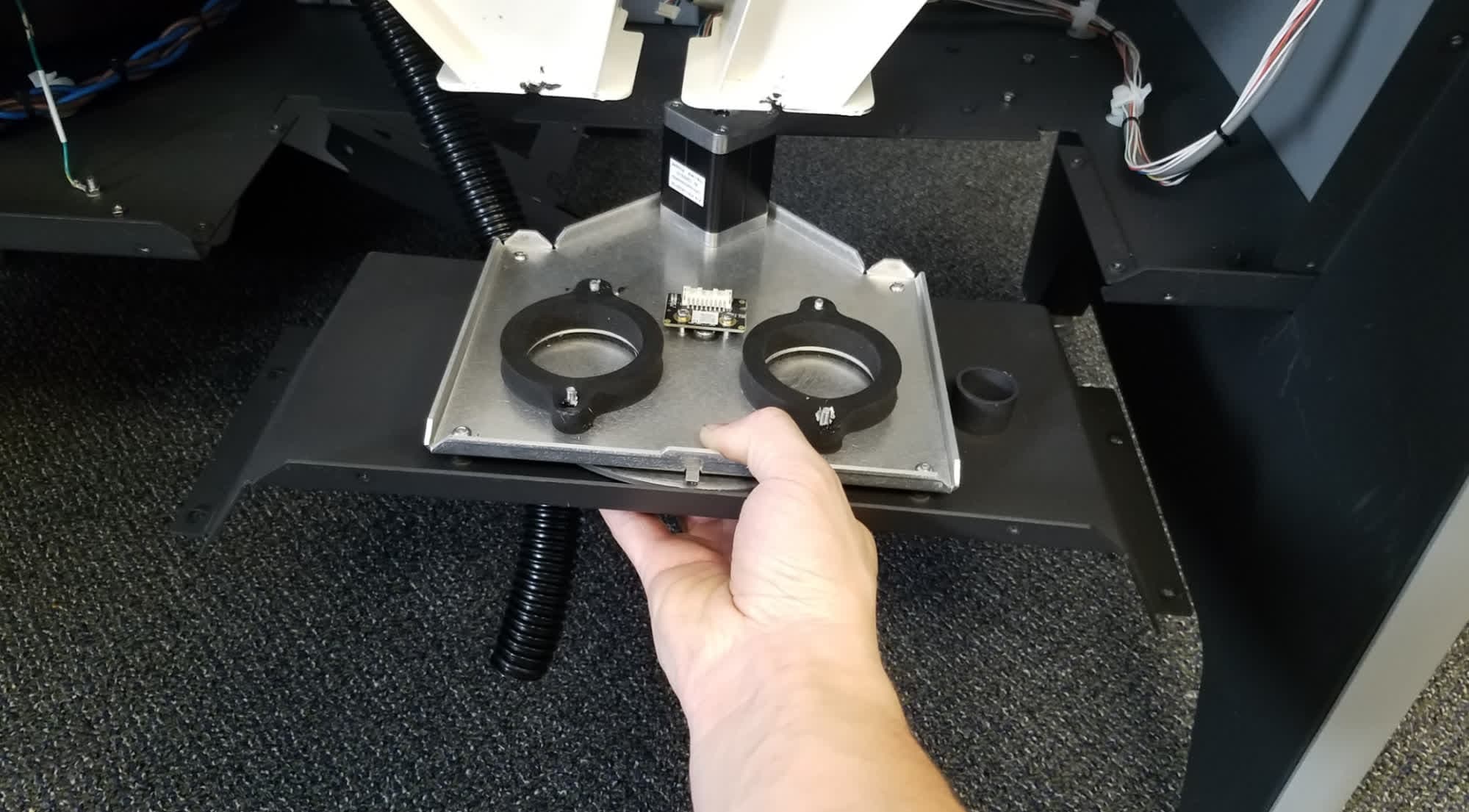
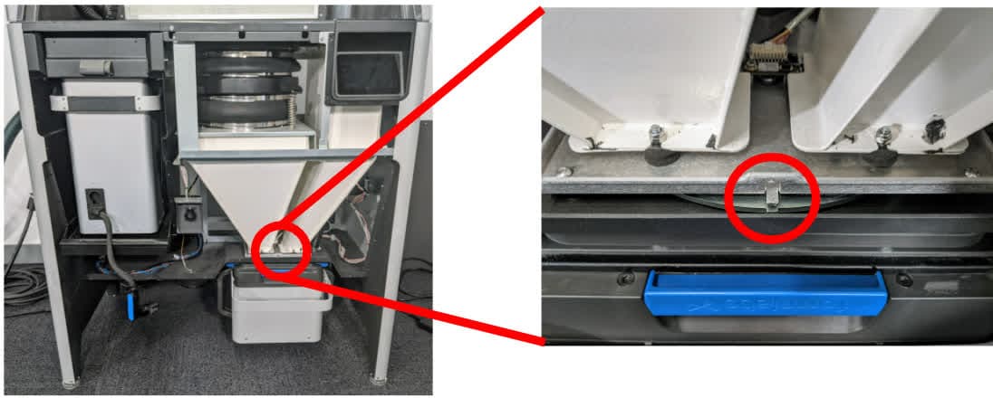
From the front of the Fuse Sift, locate the doser gear alignment tabs positioned in between the two hoppers.

Step 2: Check the alignment tabes

Verify the doser position

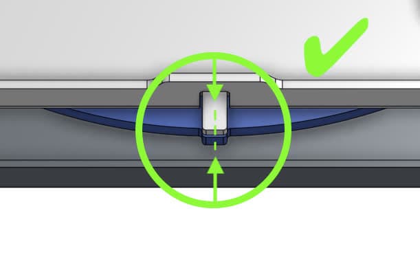
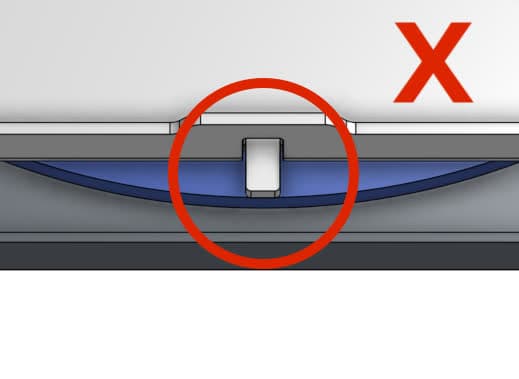
Check that the doser gear tab and top plate tab are aligned. If they are not, use your hand to rotate the motor gear at the rear of the doser assembly until the tabs are aligned. Take care not to pinch your fingers in the doser gear.

Verify the doser position

Reinstalling the rear enclosure panel

Overview: Mount and secure the rear enclosure panel after installing the new display assembly and cable.

Step 1: Prepare the rear panel retention screws

Apply a small amount of Loctite 243 or other similar threadlocker to each of the 16 black 8.0 mm M4 button screws that secure the rear panel to the Fuse Sift.

Step 2: Mount the rear panel

Mount the rear panel onto the Fuse Sift.

Step 3: Secure the rear panel

Thread one 8.0 mm M4 button screw into each of the 16 screw holes in the rear panel. Use a 2.5 mm hex driver to tighten until snug.

Fuse sift rear enclosure panel

Tip:

Start with the top three screws to hold the panel in place while you thread and tighten the remaining screws.

Reinstalling the lower front enclosure panel

Overview: Mount and secure the lower front enclosure panel after installing the new doser assembly.

Step 1: Mount the lower front enclosure panel

Mount the lower front enclosure panel onto the Fuse Sift. Align the 20 screw holes in the panel with the corresponding screw holes in the machine.

Step 2: Secure the lower front enclosure panel

Replace the lower front enclosure panel

Apply a small dab of Loctite 243 or equivalent threadlocker to each of the 20 8.0 mm M4 button head screws that secure the lower front enclosure panel to the Fuse Sift. Thread one chrome screw into both of the screw holes on the top of the panel. Thread one black screw into each of the 18 screw holes in the front of the panel. Using a 2.5 mm hex driver, tighten all 20 screws until snug.

Reinstalling the upper front enclosure panel

Overview: After reinstalling the lower front enclosure panel, reinstall the upper front enclosure panel.

Step 1: Align the upper front enclosure panel

Replace the upper front enclosure panel

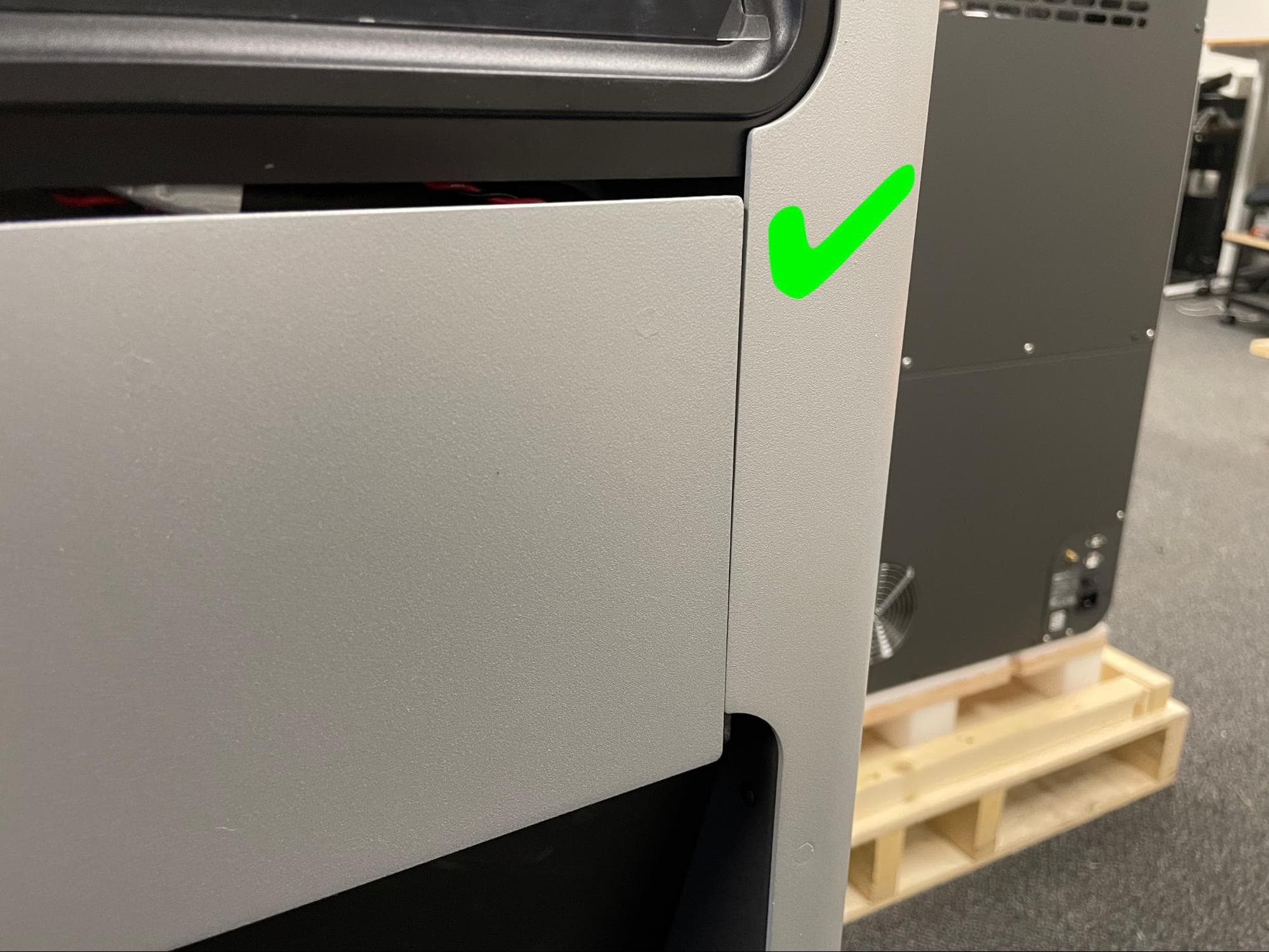
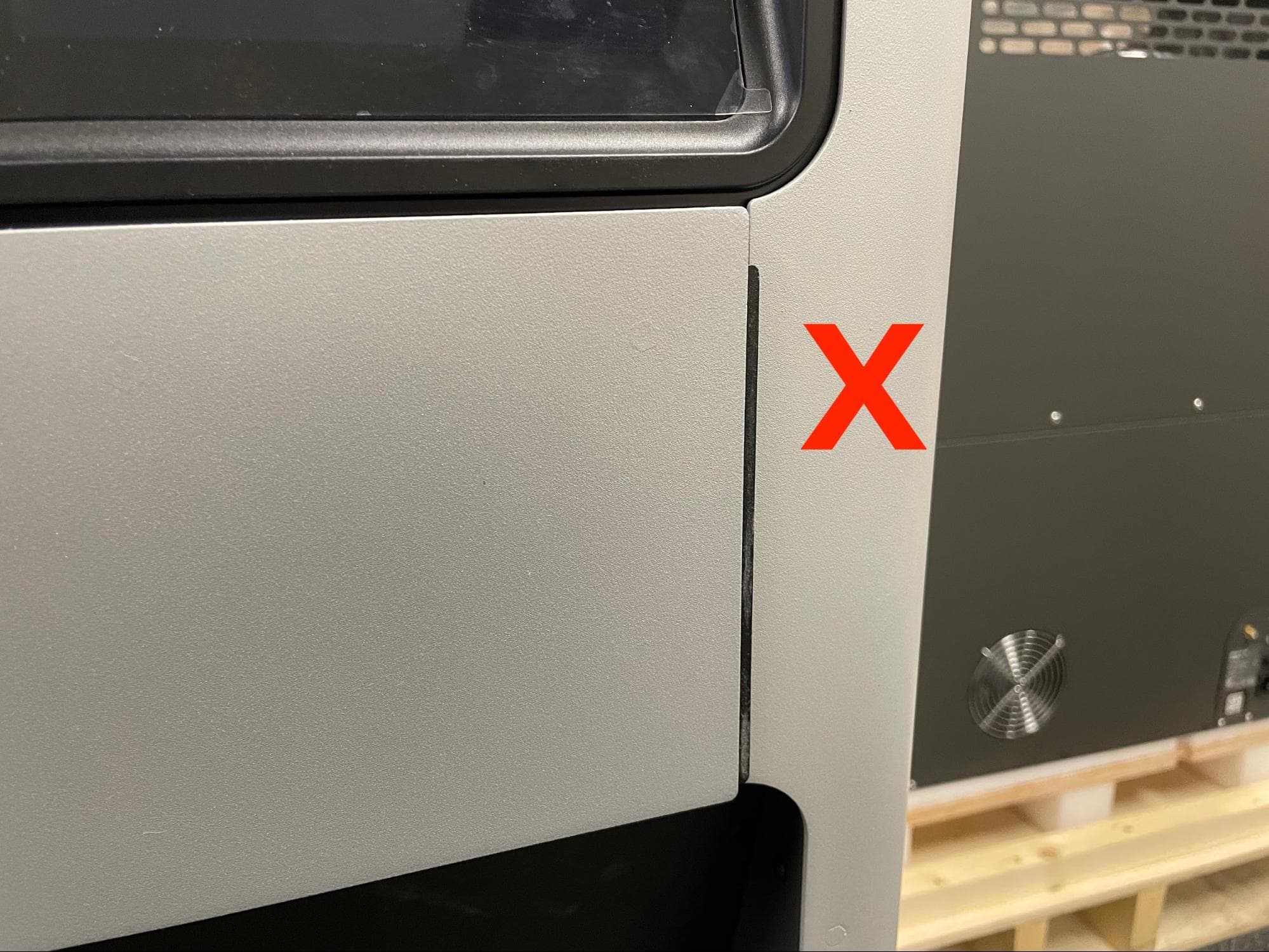
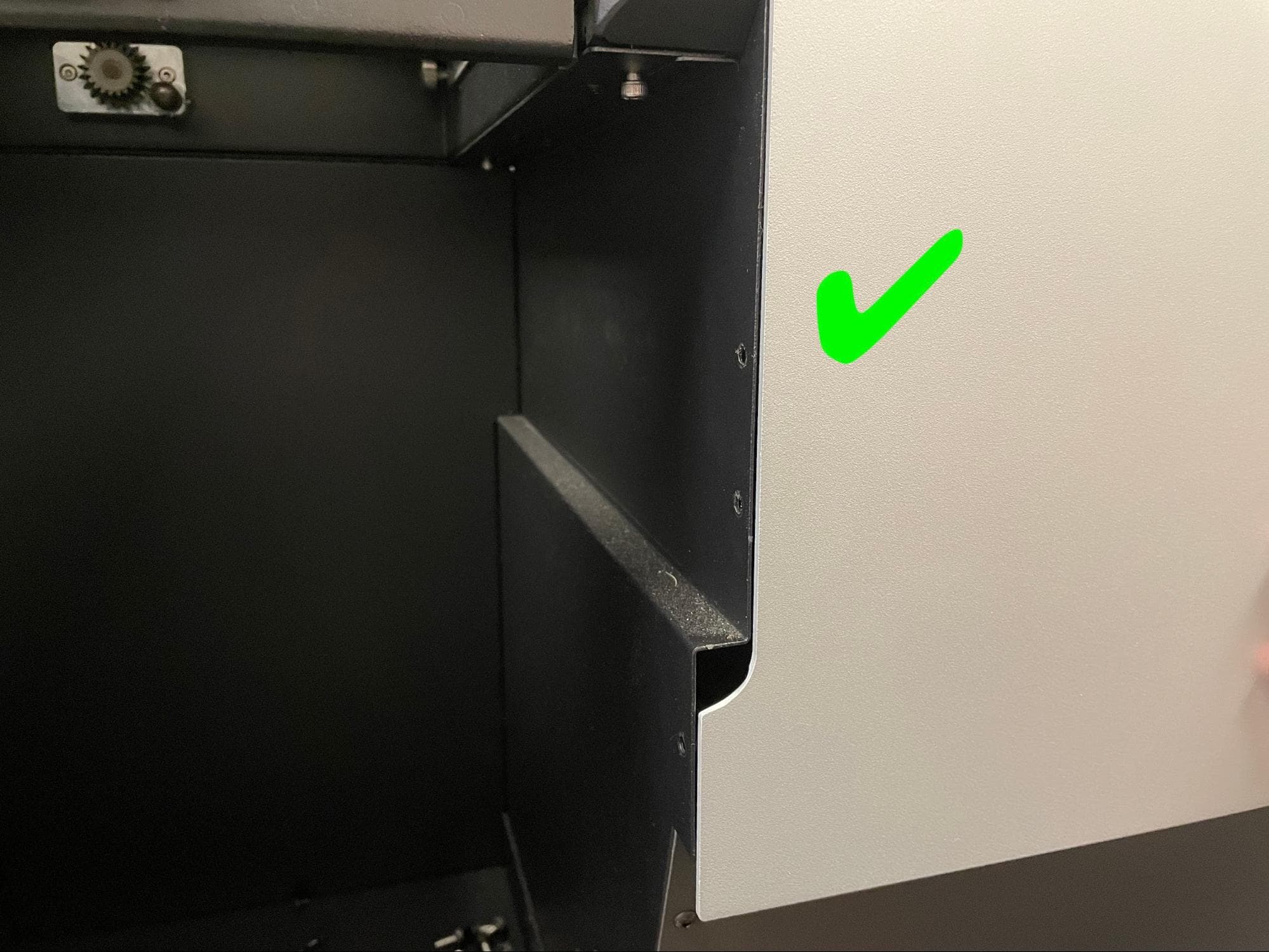
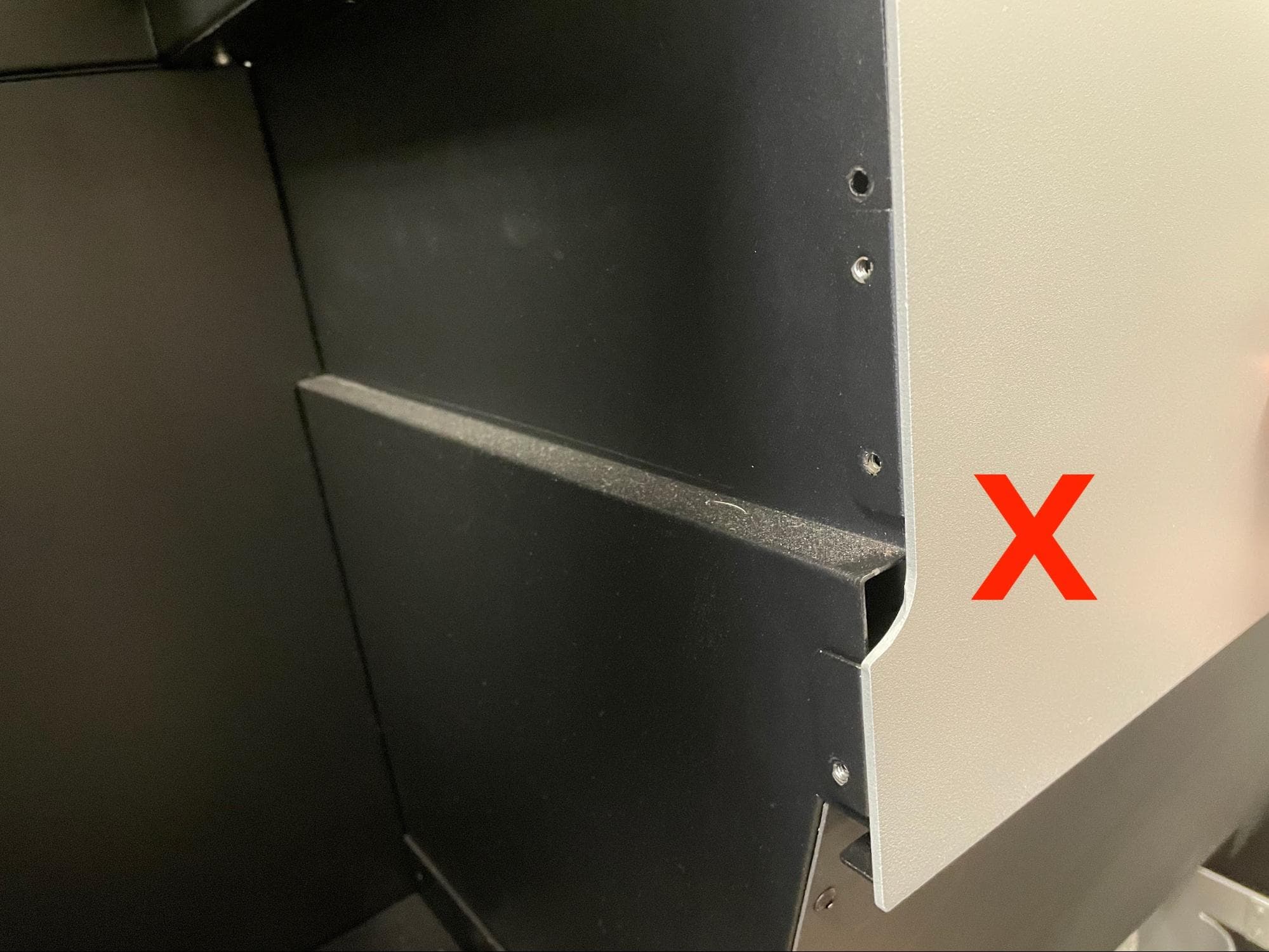
Align the upper front enclosure panel with the so that the black tab on the right-hand side of the panel and the two black flanges on the left-hand side of the panel are not visible. Start by aligning the smaller tab on the right first.

Step 2: Mount the upper front enclosure panel

Slide the panel upwards until it locks into place. Note that the panel can still fall down if knocked or hit.

Replace the upper front enclosure panel

Step 3: Secure the upper front enclosure panel

Replace the upper front enclosure panel

Apply a small dab of Loctite 243 or equivalent threadlocker to each of the seven black 8.0 mm M4 button head screws that secure the upper front enclosure panel to the Fuse Sift. Thread one of the screws into each of the seven screw holes in the panel. Using a 2.5 mm hex driver, tighten the screws until snug.

Finalizing the repair

Overview: After installing the new mixer assembly, power on the Fuse Sift and calibrate the replacement part.

Step 1: Power on the Fuse Sift

Reconnect the Fuse Sift to its power source. Flip the power switch to the ON position.

Step 2: Calibrate the doser

On the touchscreen, tap Maintenance > Calibrate Doser. Follow the instructions on the UI to complete the calibration procedure.

For more details, see our support article on calibrating the Fuse Sift doser.

Step 3: Test the doser calibration

Add the fresh and used powder you previously removed from the Fuse Sift back into their respective hoppers. Try filling a powder cartridge to verify that the doser is functioning properly. If the fill cycle completes successfully and no powder flows from the doser after the cycle is complete, then the calibration was successful. If the doser encounters an obstruction error or if powder continues to flow from the doser after the fill cycle is complete, perform the calibration procedure again.

If you encounter issues with the doser calibration routine, contact Formlabs Support or your certified service provider.